Page 1553 of 1771
Ignition Switch
Steering Lock Replacement (cont'd)
6. Remove the column holder mounting bolts and nuts.
16 N-m
(1.6 kgf-m, 12 Ibf-ft)
COLUMN
HOLDER
38 N-m
(3.9 kgf-m, 28 Ibf-ft)
7. Lower the steering column assembly.
8. Center-punch each of the two shear bolts, and drill
their heads off with a 5 mm (3/16 in) drill bit.
CAUTION: Do not damage the switch body when
removing the shear bolts.
9. Remove the shear bolts from the switch body, then
remove the steering lock assembly.
Installation:
1. Install the new ignition switch without the key
inserted.
2. Loosely tighten the new shear bolts.
3. Insert the ignition key, and check for proper opera-
tion of the steering wheel lock and that the ignition
key turns freely.
4. Tighten the shear bolts until the hex heads twist off.
SHEAR BOLT
TWIST-OFF PORTION
5. Install in the reverse order of removal.
6. Enter the anti-theft code for the radio, then enter the
customer's radio station presets.ProCarManuals.com
Page 1554 of 1771

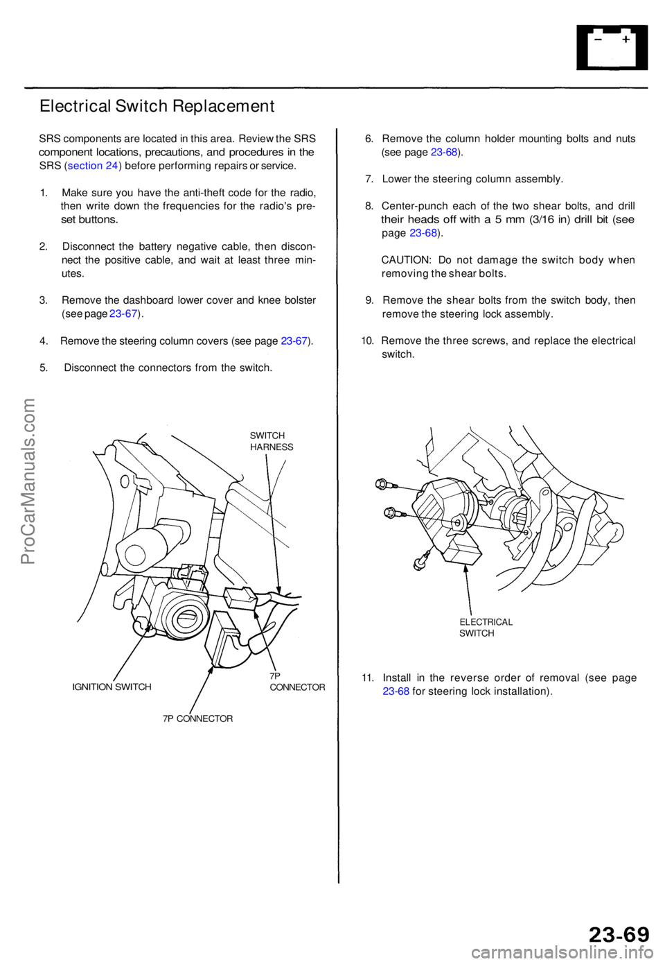
Electrical Switc h Replacemen t
SRS component s ar e locate d in thi s area . Revie w th e SR S
componen t locations , precautions , an d procedure s in th e
SR S (sectio n 24 ) befor e performin g repair s o r service .
1 . Mak e sur e yo u hav e th e anti-thef t cod e fo r th e radio ,
the n writ e dow n th e frequencie s fo r th e radio' s pre -
set buttons .
2. Disconnec t th e batter y negativ e cable , the n discon -
nec t th e positiv e cable , an d wai t a t leas t thre e min -
utes .
3 . Remov e th e dashboar d lowe r cove r an d kne e bolste r
(se e pag e 23-67 ).
4 . Remov e th e steerin g colum n cover s (se e pag e 23-67 ).
5 . Disconnec t th e connector s fro m th e switch .
SWITCHHARNES S
IGNITION SWITC H7PCONNECTO R
7 P CONNECTO R
6. Remov e th e colum n holde r mountin g bolt s an d nut s
(se e pag e 23-68 ).
7 . Lower the steerin g colum n assembly .
8 . Center-punc h eac h o f th e tw o shea r bolts , an d dril l
their head s of f wit h a 5 mm (3/1 6 in ) dril l bi t (se e
pag e 23-68 ).
CAUTION : D o no t damag e th e switc h bod y whe n
removin g th e shea r bolts .
9 . Remov e th e shea r bolt s fro m th e switc h body , the n
remov e th e steerin g loc k assembly .
10 . Remov e th e thre e screws , an d replac e th e electrica l
switch .
ELECTRICA LSWITCH
11. Instal l i n th e revers e orde r o f remova l (se e pag e
23-6 8 fo r steerin g loc k installation) .
ProCarManuals.com
Page 1558 of 1771
Starter Solenoid Test
1. Make sure you have the anti-theft code for the
radio, then write down the frequencies for the
radio's preset buttons.
2. Disconnect the battery negative cable, then discon-
nect the positive cable.
3. Check the hold-in coil for continuity between the S
terminal and the armature housing (ground). The
coil is OK if there is continuity.
4. Check the pull-in coil for continuity between the S and
M terminals. The coil is OK if there is continuity.ProCarManuals.com
Page 1559 of 1771

Starting Syste m
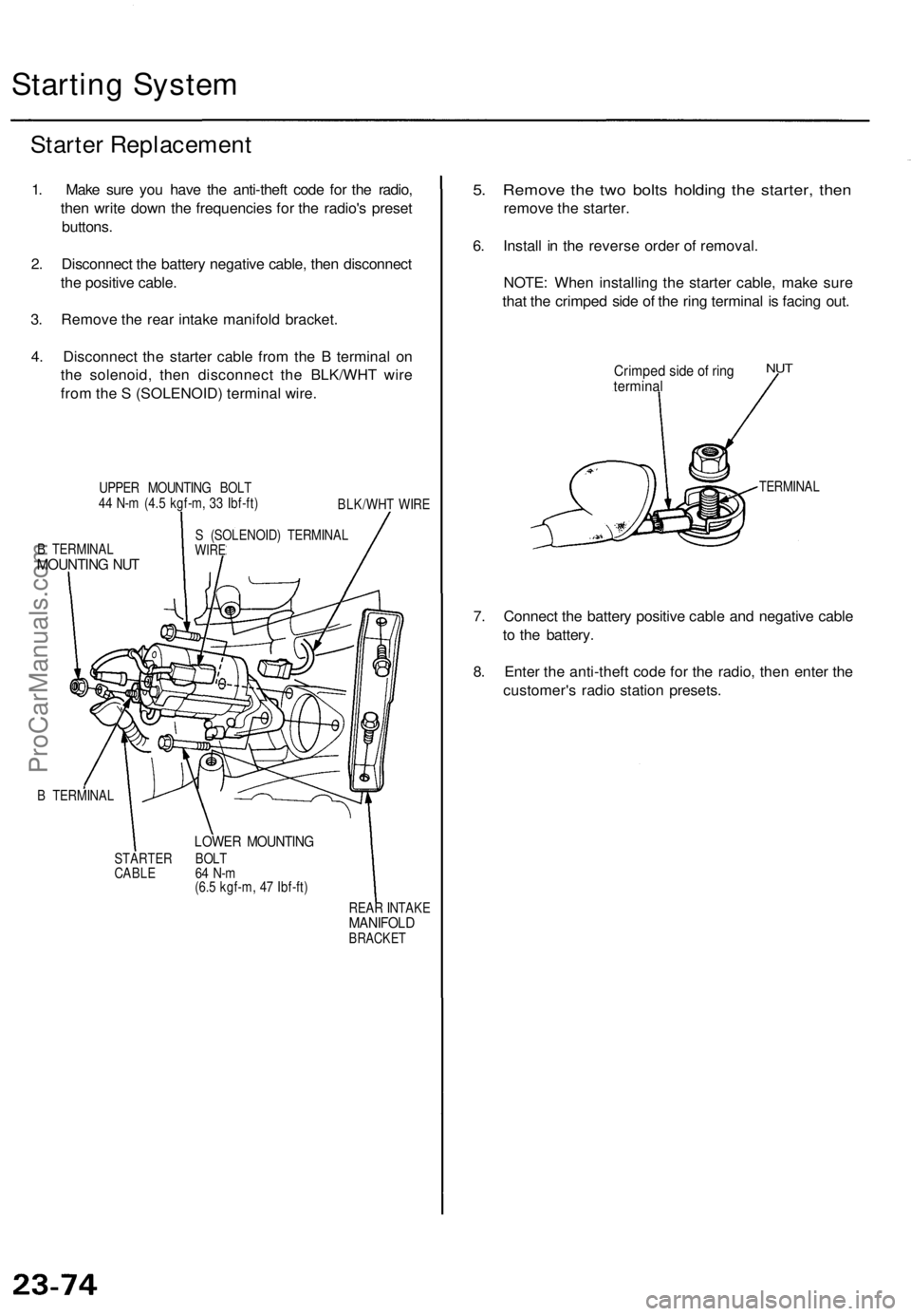
Starter Replacemen t
1. Mak e sur e yo u hav e th e anti-thef t cod e fo r th e radio ,
the n writ e dow n th e frequencie s fo r th e radio' s prese t
buttons .
2 . Disconnec t th e batter y negativ e cable , the n disconnec t
th e positiv e cable .
3 . Remov e th e rea r intak e manifol d bracket .
4 . Disconnec t th e starte r cabl e fro m th e B termina l o n
th e solenoid , the n disconnec t th e BLK/WH T wir e
fro m th e S (SOLENOID ) termina l wire .
UPPE R MOUNTIN G BOL T
4 4 N- m (4. 5 kgf-m , 3 3 Ibf-ft )
BLK/WHT WIR E
B TERMINA L
MOUNTING NU T
S (SOLENOID ) TERMINA LWIRE
B TERMINA L
LOWER MOUNTIN G
STARTER BOL T
CABL E 6 4 N- m
(6. 5 kgf-m , 4 7 Ibf-ft )
REAR INTAK E
MANIFOL DBRACKET
5. Remov e th e tw o bolt s holdin g th e starter , the n
remov e th e starter .
6 . Instal l i n th e revers e orde r o f removal .
NOTE : Whe n installin g th e starte r cable , mak e sur e
tha t th e crimpe d sid e o f th e rin g termina l i s facin g out .
Crimpe d sid e o f rin gtermina l
NUT
TERMINA L
7. Connec t th e batter y positiv e cabl e an d negativ e cabl e
t o th e battery .
8 . Ente r th e anti-thef t cod e fo r th e radio , the n ente r th e
customer' s radi o statio n presets .
ProCarManuals.com
Page 1583 of 1771

Charging Syste m
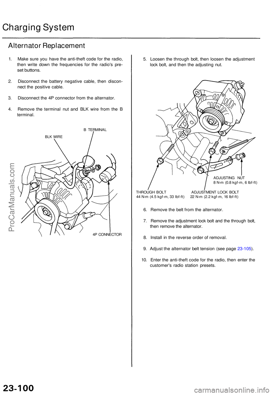
Alternato r Replacemen t
1. Mak e sur e yo u hav e th e anti-thef t cod e fo r th e radio ,
the n writ e dow n th e frequencie s fo r th e radio' s pre -
set buttons .
2. Disconnec t th e batter y negativ e cable , the n discon -
nec t th e positiv e cable .
3 . Disconnec t th e 4 P connecto r fro m th e alternator .
4 . Remov e th e termina l nu t an d BL K wir e fro m th e B
terminal .
B TERMINA L
BLK WIR E
4P CONNECTO R
5. Loose n th e throug h bolt , the n loose n th e adjustmen t
loc k bolt , an d the n th e adjustin g nut .
ADJUSTIN G NU T
8 N- m (0. 8 kgf-m , 6 Ibf-ft )
THROUG H BOL T ADJUSTMEN T LOC K BOL T
4 4 N- m (4. 5 kgf-m , 3 3 Ibf-ft ) 2 2 N- m (2. 2 kgf-m , 1 6 Ibf-ft )
6. Remov e th e bel t fro m th e alternator .
7 . Remov e th e adjustmen t loc k bol t an d th e throug h bolt ,
the n remov e th e alternator .
8 . Instal l i n th e revers e orde r o f removal .
9 . Adjus t th e alternato r bel t tensio n (se e pag e 23-105 ).
10 . Ente r th e anti-thef t cod e fo r th e radio , the n ente r th e
customer' s radi o statio n presets .
ProCarManuals.com
Page 1657 of 1771
Stereo Soun d Syste m
Componen t Locatio n Inde x
SRS component s ar e locate d in thi s area . Revie w th e SR S componen t locations , precautions , an d procedure s in th e SR S
(sectio n 24 ) befor e performin g repair s o r service .
DRIVER' S DOO R SPEAKE R
Replacement , pag e 23-19 1
WINDO W ANTENN A
Test , pag e 23-19 5
Repair , pag e 23-19 5
NOIS E CONDENSE R
Test , pag e 23-19 6
STERE O RADIO/CASSETTE/C DPLAYERRemoval , pag e 23-19 3
Terminals , pag e 23-19 4
OVERHEA D SPEAKER SReplacement , pag e 23-19 8
REAR SPEAKER SReplacement , pag e 23-19 7
TWEETER SReplacement , pag e 23-19 7
FRON T PASSENGER S DOO R SPEAKE R
Replacement , pag e 23-19 1
ANTENN A LEA D
NOIS E CONDENSE R
Test , pag e 23-19 6
ProCarManuals.com
Page 1658 of 1771
Removal
1. Mak e sur e yo u hav e th e anti-thef t cod e fo r th e radio ,
the n writ e dow n th e frequencie s fo r th e radio' s pre -
set buttons .
2. Pr y ou t th e dashboar d cente r pane l fro m th e dash -
board .
3 . Disconnec t th e connector s fro m th e climat e contro l
unit.
DASHBOAR D CENTE R PANE L
4. Remov e th e radi o pane l an d stere o radio /
cassette/C D Playe r fro m th e dashboard .
5 . Disconnec t th e 16 P an d 5 P connectors , an d antenn a
lea d fro m th e stere o radio/cassette/C D player .
5PCONNECTO RANTENNALEAD
16 P CONNECTO R
STERE O RADIO/CASSETTE/C D PLAYE R
6. Remov e th e stere o radio/cassette/C D playe r fro m
th e radi o panel .
STERE O RADIO/CASSETTE/C DPLAYER
RADIO PANE L
7. Instal l i n th e revers e orde r o f removal .
8 . Ente r th e anti-thef t cod e fo r th e radio , the n ente r th e
customer' s radi o statio n presets .
ProCarManuals.com
Page 1659 of 1771
Stereo Soun d Syste m
Stereo Radio/Cassette/C D Playe r Terminal s
TERMINA L SID E O F MAL ETERMINAL S
For ANTENN A LEA D
TERMINAL SID E O F MAL E TERMINAL S
TrmlWireConnect s to
TrmlWireConnect s to
ProCarManuals.com