1995 ACURA TL radio
[x] Cancel search: radioPage 667 of 1771
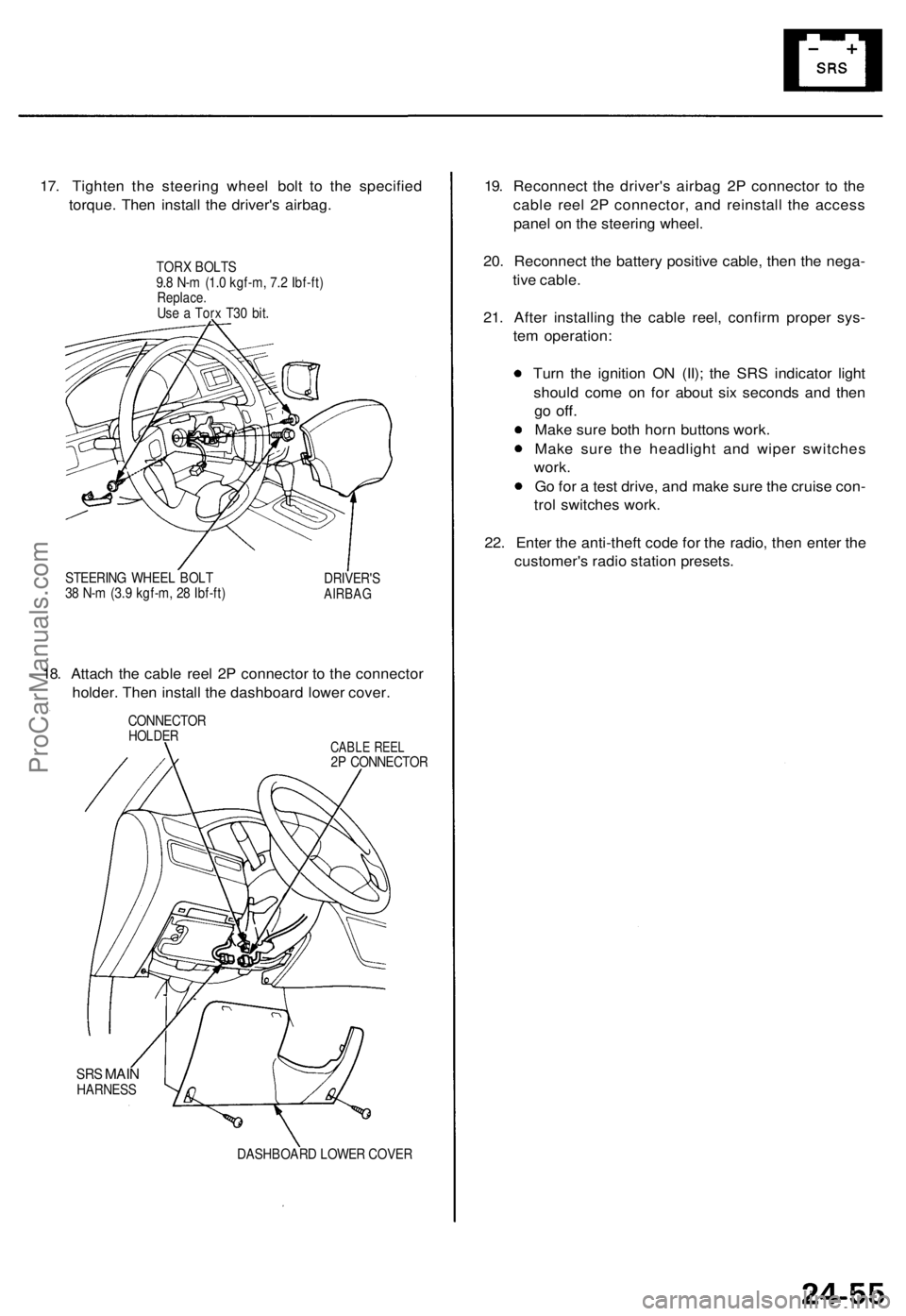
17. Tighten the steering wheel bolt to the specified
torque. Then install the driver's airbag.
TORX BOLTS
9.8 N-m (1.0 kgf-m, 7.2 Ibf-ft)
Replace.
Use a Torx T30 bit.
STEERING WHEEL BOLT
38 N-m (3.9 kgf-m, 28 Ibf-ft)
DRIVER'S
AIRBAG
18. Attach the cable reel 2P connector to the connector
holder. Then install the dashboard lower cover.
CONNECTOR
HOLDER
CABLE REEL
2P CONNECTOR
SRS
MAIN
HARNESS
DASHBOARD LOWER COVER
19. Reconnect the driver's airbag 2P connector to the
cable reel 2P connector, and reinstall the access
panel on the steering wheel.
20. Reconnect the battery positive cable, then the nega-
tive cable.
21. After installing the cable reel, confirm proper sys-
tem operation:
Turn the ignition ON (II); the SRS indicator light
should come on for about six seconds and then
go
off.
Make sure both horn buttons work.
Make sure the headlight and wiper switches
work.
Go for a test drive, and make sure the cruise con-
trol switches work.
22. Enter the anti-theft code for the radio, then enter the
customer's radio station presets.ProCarManuals.com
Page 668 of 1771
SRS Uni t
Replacemen t
CAUTION:
Durin g installatio n o r replacement , d o no t bum p
(impac t wrench , hamme r etc. ) th e are a nea r th e SR S
unit .
D o no t damag e th e SR S uni t terminal s o r connec -
tors.
Do no t disassembl e th e SR S unit ; i t ha s n o service -
abl e parts .
Stor e th e SR S uni t i n a clean , dr y area .
D o no t us e an y SR S uni t whic h ha s bee n subjecte d
t o wate r damag e o r show s sign s o f bein g droppe d o r
improperl y handled , suc h a s dents , crack s o r defor -
mation .
1 . Mak e sur e yo u hav e th e anti-thef t cod e fo r th e
radio , the n writ e dow n th e frequencie s fo r th e
radio' s prese t buttons .
2 . Disconnec t th e batter y negativ e cable , the n discon -
nec t th e positiv e cabl e fro m th e battery , an d wai t a t
leas t thre e minutes .
3 . Disconnec t th e airba g connectors .
Driver' s Side :
Remov e th e acces s pane l fro m th e steerin g wheel ,
the n disconnec t th e 2 P connecto r betwee n th e driver' s
airba g an d cabl e ree l (se e pag e 24-11 ).
Fron t Passenger' s Side :
Remov e th e glov e box .
Disconnec t th e connecto r betwee n th e fron t passen -
ger' s airba g an d SR S mai n harness . O n a '9 6 model ,
connec t th e shor t connecto r t o th e fron t passenger' s
airba g connector .
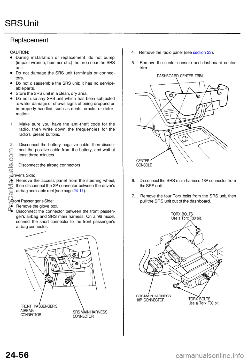
FRONT PASSENGER' S
AIRBA G
CONNECTO R
SRS MAI N HARNES SCONNECTO R
4. Remov e th e radi o pane l (se e sectio n 23 ).
5 . Remov e th e cente r consol e an d dashboar d cente r
trim.
DASHBOAR D CENTE R TRI M
CENTE R
CONSOL E
6. Disconnec t th e SR S mai n harnes s 18 P connecto r fro m
th e SR S
unit .
7. Remov e th e fou r Tor x bolt s fro m th e SR S unit , the n
pull th e SR S uni t ou t o f th e dashboard .
TORX BOLT S
Us e a Tor x T3 0 bit .
SRS MAI N HARNES S18P CONNECTO R TOR
X BOLT SUse a Tor x T3 0 bit .
ProCarManuals.com
Page 669 of 1771
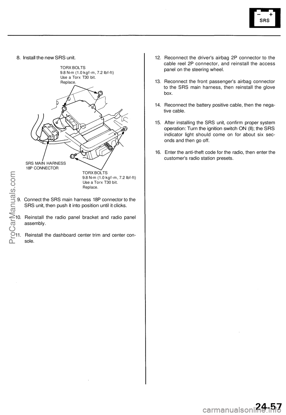
8. Install the new SRS unit.
TORX BOLTS
9.8 N-m (1.0 kgf-m, 7.2 Ibf-ft)
Use a Torx T30 bit.
Replace.
SRS MAIN HARNESS
18P CONNECTOR
TORX BOLTS
9.8 N-m (1.0 kgf-m, 7.2 Ibf-ft)
Use a Torx T30 bit.
Replace.
9. Connect the SRS main harness 18P connector to the
SRS unit, then push it into position until it clicks.
10. Reinstall the radio panel bracket and radio panel
assembly.
11. Reinstall the dashboard center trim and center con-
sole.
12. Reconnect the driver's airbag 2P connector to the
cable reel 2P connector, and reinstall the access
panel on the steering wheel.
13. Reconnect the front passenger's airbag connector
to the SRS main harness, then reinstall the glove
box.
14. Reconnect the battery positive cable, then the nega-
tive cable.
15. After installing the SRS unit, confirm proper system
operation: Turn the ignition switch ON (II); the SRS
indicator light should come on for about six sec-
onds and then go off.
16. Enter the anti-theft code for the radio, then enter the
customer's radio station presets.ProCarManuals.com
Page 719 of 1771
Engine Removal/Installation
Removal
• Make sure jacks and safety stands are placed properly
and hoist brackets are attached to the correct positions
on the engine.
• Make sure the car will not roll off stands and fall
while you are working under it.
CAUTION:
• Use fender covers to avoid damaging painted sur-
face.
• Unplug the wiring connectors carefully while holding
the connector portion to avoid damage.
• Mark all wiring and hoses to avoid misconnection.
Also, be sure that they do not contact other wiring
or hoses or interfere with other parts.
1. Secure the hood open as far as possible.
2. Make sure you have the anti-theft code for the radio,
then write down the frequencies for the radio's pre-
set buttons.
3. Disconnect the battery negative terminal first, then
the positive terminal.
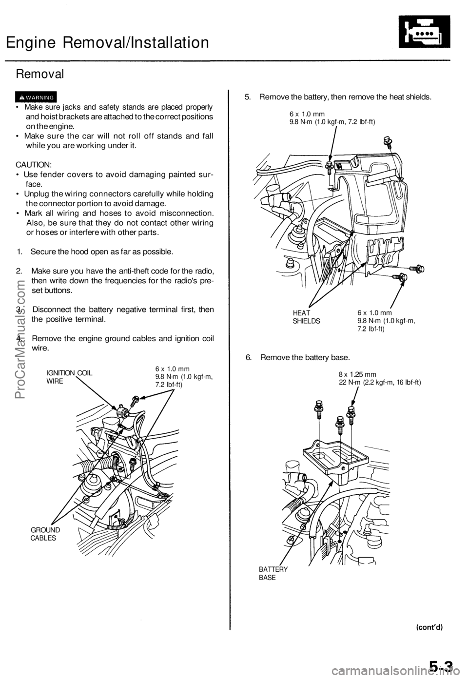
4. Remove the engine ground cables and ignition coil
wire.
IGNITION COIL
WIRE
GROUND
CABLES
6 x 1.0 mm
9.8 N-m (1.0 kgf-m,
7.2 Ibf-ft)
5. Remove the battery, then remove the heat shields.
6 x 1.0 mm
9.8 N-m (1.0 kgf-m, 7.2 Ibf-ft)
HEAT
SHIELDS
6. Remove the battery base.
6 x 1.0 mm
9.8 N-m (1.0 kgf-m,
7.2 Ibf-ft)
8 x
1.25
mm
22 N-m (2.2 kgf-m, 16 Ibf-ft)
BATTERY
BASEProCarManuals.com
Page 731 of 1771
Check tha t th e sprin g cli p o n th e en d o f eac h drive -
shaf t click s int o place .
CAUTION : Us e ne w sprin g clips .
Refil l th e coolin g system .
Blee d ai r fro m th e coolin g syste m a t th e blee d bol t
wit h th e heate r valv e ope n (se e pag e 10-5 ).
Adjus t th e throttl e cabl e (se e sectio n 11 ).
Adjus t th e shif t cabl e (se e sectio n 14 ).
Adjus t th e tensio n o f th e followin g driv e belts .
Alternato r bel t (se e sectio n 23 ).
P/ S pum p bel t (se e sectio n 17 ).
A/ C compresso r bel t (se e sectio n 22 ).
Clea n th e batter y post s an d cabl e terminal s wit h sand -
paper , assembl e them , the n appl y greas e t o preven t
corrosion .
Inspec t fo r fue l leakag e (se e sectio n 11 ).
Afte r assemblin g fue l lin e parts , tur n o n th e igni -
tio n switc h (d o no t operat e th e starter ) s o tha t th e
fue l pum p operate s fo r approximatel y tw o sec -
ond s an d th e fue l lin e pressurizes .
Repea t thi s operatio n tw o o r thre e times , an d
chec k fo r fue l leakag e a t an y poin t i n th e fue l line .
Refil l th e engin e wit h engin e oi l (se e pag e 8-4 ).
Refil l th e transmissio n wit h AT F (se e sectio n 14 ).
Refil l th e differentia l wit h differentia l oi l (se e sectio n 15).
Enter th e anti-thef t cod e fo r th e radio , the n ente r th e
customer' s radi o statio n presets .
ProCarManuals.com
Page 750 of 1771
Cylinder Hea d
Remova l
Engine remova l i s no t require d fo r thi s procedure .
Mak e sur e jack s an d safet y stand s ar e
place d properl y an d hois t bracket s ar e attache d to cor -
rec t positio n o n th e engine .
CAUTION :
• Us e fende r cover s t o avoi d damagin g painte d sur -
faces .
• Unplu g th e wirin g connector s carefull y whil e holdin g
th e connecto r portio n to avoi d damage .
• T o avoi d damagin g th e cylinde r head , wai t unti l th e
engin e coolan t temperatur e drop s belo w 100° F
(38°C ) befor e loosenin g th e retainin g bolts .
NOTE :
• Mar k al l wirin g an d hose s t o avoi d misconnection .
Also , b e sur e tha t the y d o no t contac t othe r wirin g o r
hoses , o r interfer e wit h othe r parts .
• Inspec t th e timin g bel t befor e removin g th e cylinde r
head .
• Tur n th e crankshaf t pulle y s o tha t th e No . 1 pisto n i s
a t to p dea d cente r (se e pag e 6-12 ).
1 . Mak e sur e yo u hav e th e anti-thef t cod e fo r th e radio ,
the n writ e dow n th e frequencie s fo r th e radio' s pre -
se t buttons .
2 . Disconnec t th e negativ e termina l fro m th e battery .
3 . Drai n th e engin e coolan t (se e pag e 10-5 ).
Remov e th e radiato r cap to spee d draining .
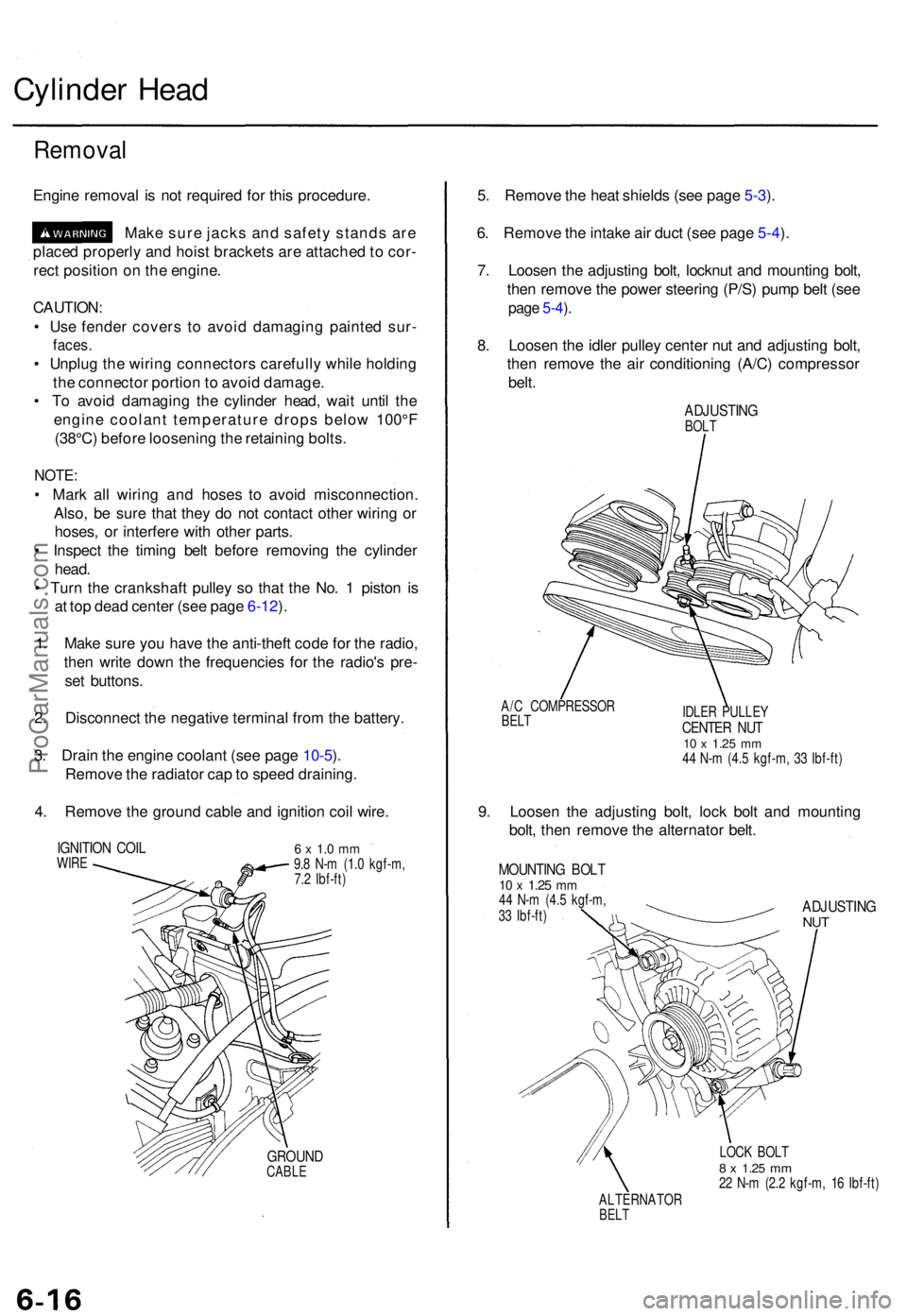
4 . Remov e th e groun d cabl e an d ignitio n coi l wire .
IGNITIO N COI LWIRE6 x 1. 0 m m9.8 N- m (1. 0 kgf-m ,
7. 2 Ibf-ft )
GROUN DCABLE
5. Remov e th e hea t shield s (se e pag e 5-3 ).
6 . Remov e th e intak e ai r duc t (se e pag e 5-4 ).
7 . Loose n th e adjustin g bolt , locknu t an d mountin g bolt ,
the n remov e th e powe r steerin g (P/S ) pum p bel t (se e
page 5-4 ).
8 . Loose n th e idle r pulle y cente r nu t an d adjustin g bolt ,
the n remov e th e ai r conditionin g (A/C ) compresso r
belt .
ADJUSTIN GBOLT
A/ C COMPRESSO R
BELTIDLE R PULLE YCENTER NU T10 x 1.2 5 mm44 N- m (4. 5 kgf-m , 3 3 Ibf-ft )
9. Loose n th e adjustin g bolt , loc k bol t an d mountin g
bolt , the n remov e th e alternato r belt .
MOUNTIN G BOL T10 x 1.2 5 mm44 N- m (4. 5 kgf-m ,
3 3 Ibf-ft )ADJUSTIN GNUT
LOC K BOL T8 x 1.2 5 mm22 N- m (2. 2 kgf-m , 1 6 Ibf-ft )
ALTERNATO R
BELT
ProCarManuals.com
Page 775 of 1771
Cylinder Head
Installation (cont'd)
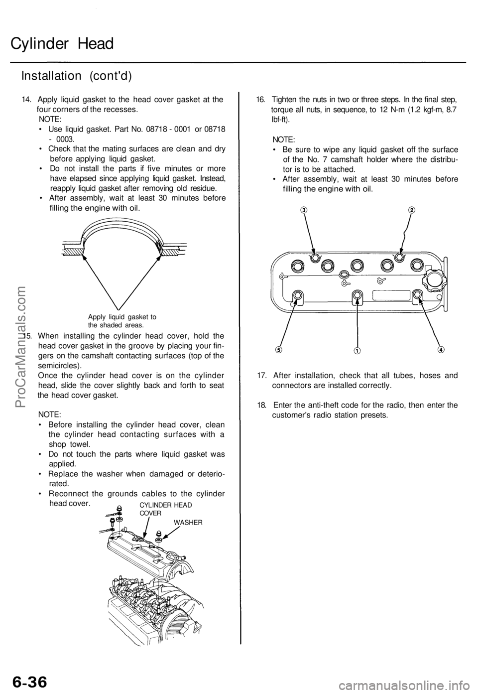
14. Apply liquid gasket to the head cover gasket at the
four corners of the recesses.
NOTE:
• Use liquid gasket. Part No. 08718 - 0001 or 08718
- 0003.
• Check that the mating surfaces are clean and dry
before applying liquid gasket.
• Do not install the parts if five minutes or more
have elapsed since applying liquid gasket. Instead,
reapply liquid gasket after removing old residue.
• After assembly, wait at least 30 minutes before
filling the engine with oil.
15.
Apply liquid gasket to
the shaded areas.
When installing the cylinder head cover, hold the
head cover gasket in the groove by placing your fin-
gers on the camshaft contacting surfaces (top of the
semicircles).
Once the cylinder head cover is on the cylinder
head, slide the cover slightly back and forth to seat
the head cover gasket.
NOTE:
• Before installing the cylinder head cover, clean
the cylinder head contacting surfaces with a
shop towel.
• Do not touch the parts where liquid gasket was
applied.
• Replace the washer when damaged or deterio-
rated.
• Reconnect the grounds cables to the cylinder
head cover.
16. Tighten the nuts in two or three steps. In the final step,
torque all nuts, in sequence, to 12 N-m (1.2 kgf-m, 8.7
Ibf-ft).
NOTE:
• Be sure to wipe any liquid gasket off the surface
of the No. 7 camshaft holder where the distribu-
tor is to be attached.
• After assembly, wait at least 30 minutes before
filling the engine with oil.
17. After installation, check that all tubes, hoses and
connectors are installed correctly.
18. Enter the anti-theft code for the radio, then enter the
customer's radio station presets.
CYLINDER HEAD
COVER
WASHERProCarManuals.com
Page 820 of 1771
HO2S
Replacemen t
Primary HO2S :
1 . Mak e sur e yo u hav e th e anti-thef t cod e fo r th e
radio , the n writ e dow n th e frequencie s fo r th e
radio' s prese t buttons .
2 . Disconnec t th e batter y negativ e termina l first , the n
th e positiv e terminal .
3 . Remov e th e battery , the n remov e th e hea t shield s
(se e pag e 5-3 ).
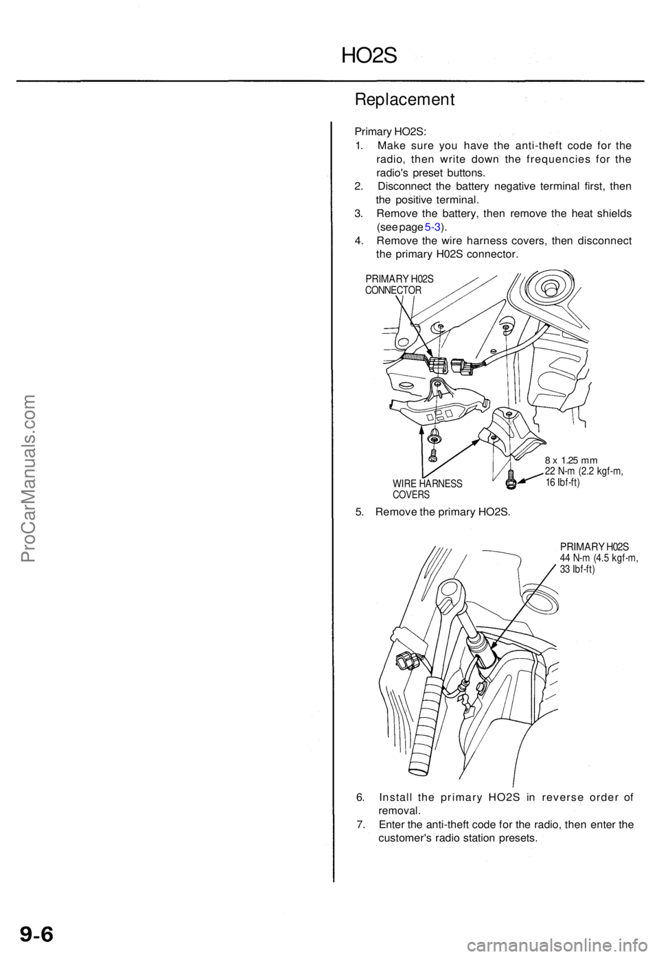
4 . Remov e th e wir e harnes s covers , the n disconnec t
th e primar y H02 S connector .
PRIMARY H02 SCONNECTO R
WIR E HARNES S
COVERS
5. Remov e th e primar y HO2S .
8 x 1.2 5 mm22 N- m (2. 2 kgf-m ,
1 6 Ibf-ft )
PRIMAR Y H02 S44 N- m (4. 5 kgf-m ,
3 3 Ibf-ft )
6. Instal l th e primar y HO2 S i n revers e orde r o f
removal .
7. Ente r th e anti-thef t cod e fo r th e radio , the n ente r th e
customer' s radi o statio n presets .
ProCarManuals.com