1995 ACURA TL radio
[x] Cancel search: radioPage 1121 of 1771
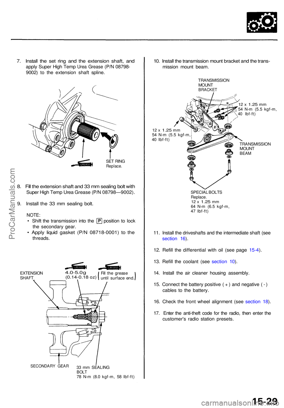
7. Instal l th e se t rin g an d th e extensio n shaft , an d
appl y Supe r Hig h Tem p Urea Greas e (P/N 08798-
9002 ) t o th e extensio n shaf t spline .
SET RIN GReplace .
8. Fil l th e extensio n shaf t an d 3 3 m m sealin g bol t wit h
Supe r Hig h Tem p Ure a Greas e (P/ N 08798—9002) .
9. Instal l th e 3 3 m m sealin g bolt .
NOTE :
• Shif t th e transmissio n int o th e positio n t o loc k
the secondar y gear .
• Appl y liqui d gaske t (P/ N 08718-0001 ) t o th e
threads .
EXTENSIO NSHAFT
4.0-5.0 g(0.14-0.1 8 oz)
33 m m SEALIN GBOLT78 N- m (8. 0 kgf-m , 5 8 Ibf-ft )
10. Instal l th e transmissio n moun t bracke t an d th e trans -
missio n moun t beam .
TRANSMISSIO N
MOUN T
BRACKE T
12 x 1.2 5 mm54 N- m (5. 5 kgf-m ,40 Ibf-ft )
12 x 1.2 5 mm54 N- m (5. 5 kgf-m ,
4 0 Ibf-ft )
TRANSMISSION
MOUN T
BEAM
SPECIA L BOLT SReplace .12 x 1.2 5 mm64 N- m (6. 5 kgf-m ,
4 7 Ibf-ft )
11. Instal l th e driveshaft s an d th e intermediat e shaf t (se e
sectio n 16 ).
12 . Refil l th e differentia l wit h oi l (se e pag e 15-4 ).
13 . Refil l th e coolan t (se e sectio n 10 ).
14 . Instal l th e ai r cleane r housin g assembly .
15 . Connec t th e batter y positiv e ( + ) an d negativ e ( - )
cable s t o th e battery .
16 . Chec k th e fron t whee l alignmen t (se e sectio n 18 ).
17 . Ente r th e anti-thef t cod e fo r th e radio , the n ente r th e
customer' s radi o statio n presets .
SECONDAR Y GEA R
Fill th e greas e
unti l surfac e end .
ProCarManuals.com
Page 1299 of 1771
Troubleshooting Precautions
ABS Indicator Light:
The ABS indicator light comes on for three seconds and then goes off when the control unit detects no problem during the
initial diagnosis right after the engine starts. However, the ABS indicator light can stay on for up to 40 seconds when the
control unit starts to check for pump overrun, etc. during the initial diagnosis. The ABS indicator light comes on, and the
ABS control unit memorizes the diagnostic trouble code (DTC) under certain conditions.
The parking brake is applied for more than 30 seconds while the vehicle is being driven. (DTC 2-1)
The transmission downshifted excessively. (DTC 4-1, 4-2)
The vehicle loses traction, and the front wheels spin for more than one minute when starting from a stuck condition on
a muddy, snowy, or sandy road. (DTC 4-8)
Tire adhesion is lost due to excessive cornering speed. (DTC 5, 5-4, 5-8)
The vehicle is driven on an extremely rough road. (DTC 8-1)
The vehicle is interfered by strong radio waves (noise), for example, illegal radio, etc. (DTC 8-2)
NOTE: If there is any trouble in the system, the ABS indicator light comes on during driving.
Diagnostic Trouble Code (DTC):
When the control unit detects a problem and the ABS indicator light comes on, the control unit memorizes the DTC.
The control unit has three memory registers. When a problem occurs, the control unit stores the DTC in the first memory
register. If another problem occurs, or the same problem occurs again, the control unit moves the first DTC to the next
memory register, and stores the second DTC in the first register. If there's a third problem occurrence, the two existing
DTCs are moved up one register, and the third DTC is stored in the first register. If problems continue to occur, the oldest
problem is moved out of the last register and lost, and the most recent problem is stored in the first register. When the
same problem occurs three times, the same DTC is stored in all memory registers. (Refer to the Symptom-to-System
Chart for diagnostic period.)
The most recent DTC is indicated first, and the oldest DTC is indicated last.
The DTCs are erased from the control unit when the ABS control unit +B2 power supply or connector is disconnected.
The control unit's memory can be erased by disconnecting the ABS B2 fuse for more than three seconds.
Self-diagnosis:
There are three self-diagnosises described below.
Initial diagnosis: Performed right after the engine starts until the ABS indicator light goes off.
Regular diagnosis: Continuously performed (under some conditions) after the ABS indicator light goes off until the
engine stops.
Individual part/system diagnosis: Diagnosis about a specific part/system under its operating conditions.
The CPU (central processing unit) controls the following when it detects a problem during self-diagnosis:
Turns the ABS indicator light ON.
Turns the front and rear fail-safe relays off.
Stops the ABS control.
Stops the ABS pump. (The pump may work under some conditions.)
After the DTC is stored in the control unit, the CPU stops self-diagnosis.ProCarManuals.com
Page 1417 of 1771
Dashboard
Component Removal/Installation (cont'd)
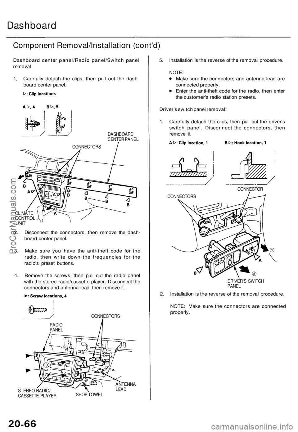
Dashboard center panel/Radio panel/Switch panel
removal:
1, Carefully detach the clips, then pull out the dash-
board center panel.
DASHBOARD
CENTER PANEL
CLIMATE
CONTROL
UNIT
2. Disconnect the connectors, then remove the dash-
board center panel.
3. Make sure you have the anti-theft code for the
radio, then write down the frequencies for the
radio's preset buttons.
4. Remove the screws, then pull out the radio panel
with the stereo radio/cassette player. Disconnect the
connectors and antenna lead, then remove it.
CONNECTORS
STEREO RADIO/
CASSETTE PLAYER
ANTENNA
LEAD
SHOP TOWEL
5. Installation is the reverse of the removal procedure.
NOTE:
Make sure the connectors and antenna lead are
connected properly.
Enter the anti-theft code for the radio, then enter
the customer's radio station presets.
Driver's switch panel removal:
1. Carefully detach the clips, then pull out the driver's
switch panel. Disconnect the connectors, then
remove it.
DRIVER'S SWITCH
PANEL
2. Installation is the reverse of the removal procedure.
NOTE: Make sure the connectors are connected
properly.
RADIO
PANEL
CONNECTOR
CONNECTORS
CONNECTORSProCarManuals.com
Page 1419 of 1771
Replacement
SRS component s ar e locate d in thi s area . Revie w th e SR S
componen t locations , precautions , an d procedure s i n th e
SR S sectio n 24 befor e preformin g repair s o r service .
NOTE:
• A n assistan t i s helpfu l whe n removin g an d installin g
th e dashboard .
• Tak e car e no t t o scratc h th e dashboard , bod y an d
relate d parts .
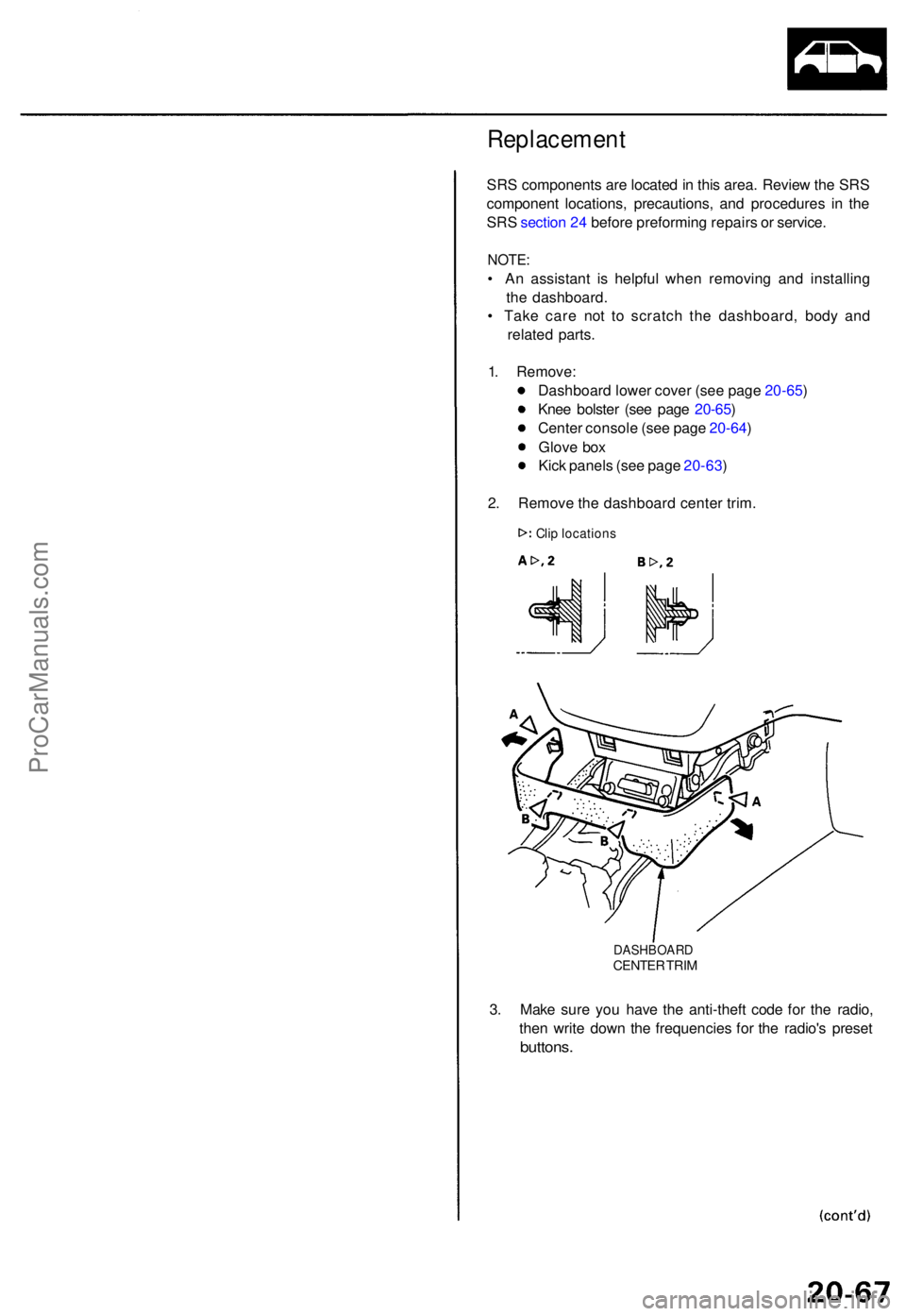
1 . Remove :
Dashboar d lowe r cove r (se e pag e 20-65 )
Kne e bolste r (se e pag e 20-65 )
Cente r consol e (se e pag e 20-64 )
Glov e bo x
Kic k panel s (se e pag e 20-63 )
2 . Remov e th e dashboar d cente r trim .
DASHBOAR DCENTER TRI M
3. Mak e sur e yo u hav e th e anti-thef t cod e fo r th e radio ,
the n writ e dow n th e frequencie s fo r th e radio' s prese t
buttons .
Clip location s
ProCarManuals.com
Page 1421 of 1771
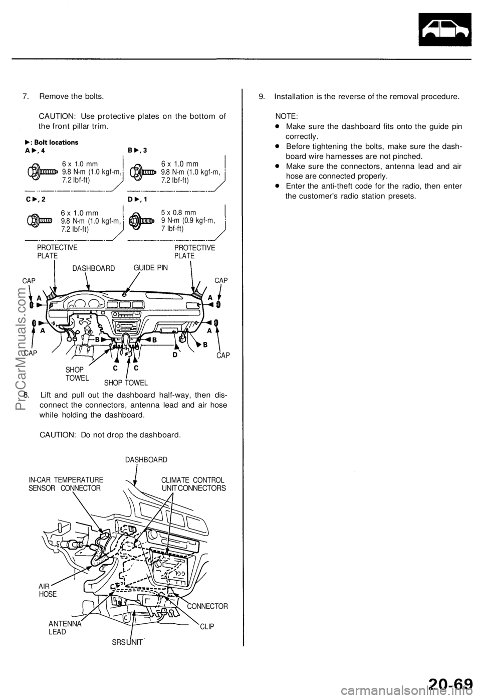
7. Remov e th e bolts .
CAUTION : Us e protectiv e plate s o n th e botto m o f
th e fron t pilla r trim .
6 x 1. 0 m m9.8 N- m (1. 0 kgf-m ,
7. 2 Ibf-ft )
6 x 1. 0 m m9.8 N- m (1. 0 kgf-m ,
7. 2 Ibf-ft )
6 x 1. 0 m m9.8 N- m (1. 0 kgf-m ,
7. 2 Ibf-ft )
PROTECTIV E
PLATE
CAP CA
P
IN-CA R TEMPERATUR E
SENSO R CONNECTO RDASHBOAR
D
CLIMAT E CONTRO LUNIT CONNECTOR S
ANTENNALEAD
SRS UNI T 9
. Installatio n i s th e revers e o f th e remova l procedure .
NOTE:
Make sur e th e dashboar d fit s ont o th e guid e pi n
correctly .
Before tightenin g th e bolts , mak e sur e th e dash -
boar d wir e harnesse s ar e no t pinched .
Mak e sur e th e connectors , antenn a lea d an d ai r
hos e ar e connecte d properly .
Ente r th e anti-thef t cod e fo r th e radio , the n ente r
th e customer' s radi o statio n presets .
CLIP
CONNECTO R
8. Lif t an d pul l ou t th e dashboar d half-way , the n dis -
connec t th e connectors , antenn a lea d an d ai r hos e
whil e holdin g th e dashboard .
CAUTION : D o no t dro p th e dashboard .
CAP
SHO P TOWE L
SHO
P
TOWE L
CAP
DASHBOAR DGUIDE PI N
5 x 0. 8 m m9 N- m (0. 9 kgf-m ,
7 Ibf-ft )
PROTECTIV E
PLATE
AIRHOS E
ProCarManuals.com
Page 1549 of 1771
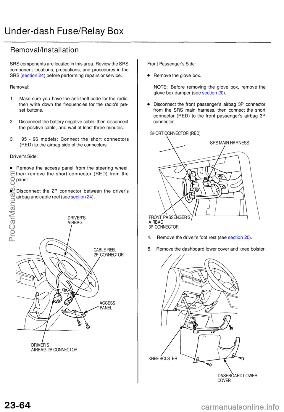
Under-dash Fuse/Rela y Bo x
Removal/Installatio n
SRS component s ar e locate d in thi s area . Revie w th e SR S
componen t locations , precautions , an d procedure s i n th e
SR S (sectio n 24 ) befor e performin g repair s o r service .
Removal :
1. Mak e sur e yo u hav e th e anti-thef t cod e fo r th e radio ,
the n writ e dow n th e frequencie s fo r th e radio' s pre -
se t buttons .
2 . Disconnec t th e batter y negativ e cable , the n disconnec t
th e positiv e cable , an d wai t a t leas t thre e minutes .
3 . '9 5 - 9 6 models : Connec t th e shor t connector s
(RED ) t o th e airba g sid e o f th e connectors .
Driver' s Side :
Remov e th e acces s pane l fro m th e steerin g wheel ,
the n remov e th e shor t connecto r (RED ) fro m th e
panel .
Disconnec t th e 2 P connecto r betwee n th e driver' s
airba g an d cabl e ree l (se e sectio n 24 ).
DRIVER' SAIRBAG
CABLE REE L2P CONNECTO R
ACCESSPANEL
DRIVER' SAIRBAG 2 P CONNECTO R
Front Passenger' s Side :
Remov e th e glov e box .
NOTE : Befor e removin g th e glov e box , remov e th e
glov e bo x dampe r (se e sectio n 20 ).
Disconnec t th e fron t passenger' s airba g 3 P connecto r
fro m th e SR S mai n harness , the n connec t th e shor t
connecto r (RED ) t o th e fron t passenger' s airba g 3 P
connector .
SHORT CONNECTO R (RED )
SRS MAI N HARNES S
FRONT PASSENGER' SAIRBAG3P CONNECTO R
4. Remov e th e driver' s foo t res t (se e sectio n 20 ).
5 . Remov e th e dashboar d lowe r cove r an d kne e bolster .
KNEE BOLSTE R
DASHBOARD LOWE R
COVER
ProCarManuals.com
Page 1550 of 1771
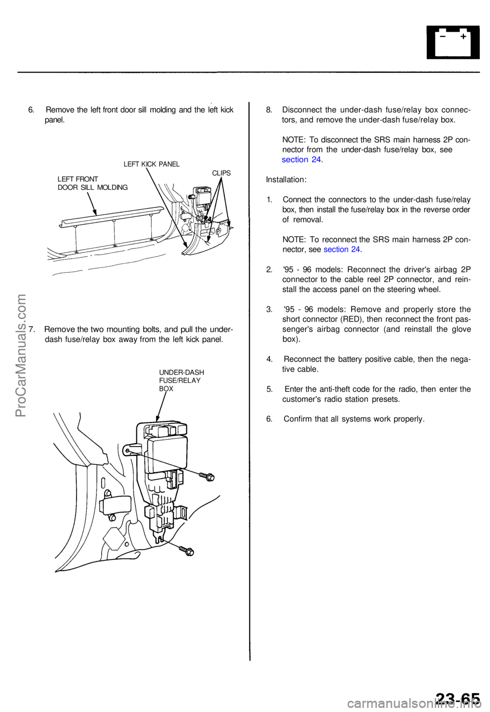
6. Remov e th e lef t fron t doo r sil l moldin g an d th e lef t kic k
panel .
LEFT KIC K PANE L
LEFT FRON TDOOR SIL L MOLDIN G
CLIPS
7. Remov e th e tw o mountin g bolts , an d pul l th e under -
dash fuse/rela y bo x awa y fro m th e lef t kic k panel .
UNDER-DAS HFUSE/RELAYBOX
8. Disconnec t th e under-das h fuse/rela y bo x connec -
tors , an d remov e th e under-das h fuse/rela y box .
NOTE : T o disconnec t th e SR S mai n harnes s 2 P con -
necto r fro m th e under-das h fuse/rela y box , se e
sectio n 24 .
Installation :
1 . Connec t th e connector s t o th e under-das h fuse/rela y
box , the n instal l th e fuse/rela y bo x in th e revers e orde r
o f removal .
NOTE : T o reconnec t th e SR S mai n harnes s 2 P con -
nector , se e sectio n 24 .
2 . '9 5 - 9 6 models : Reconnec t th e driver' s airba g 2 P
connecto r t o th e cabl e ree l 2 P connector , an d rein -
stal l th e acces s pane l o n th e steerin g wheel .
3 . '9 5 - 9 6 models : Remov e an d properl y stor e th e
shor t connecto r (RED) , the n reconnec t th e fron t pas -
senger' s airba g connecto r (an d reinstal l th e glov e
box).
4. Reconnec t th e batter y positiv e cable , the n th e nega -
tiv e cable .
5 . Ente r th e anti-thef t cod e fo r th e radio , the n ente r th e
customer' s radi o statio n presets .
6 . Confir m tha t al l system s wor k properly .
ProCarManuals.com
Page 1552 of 1771
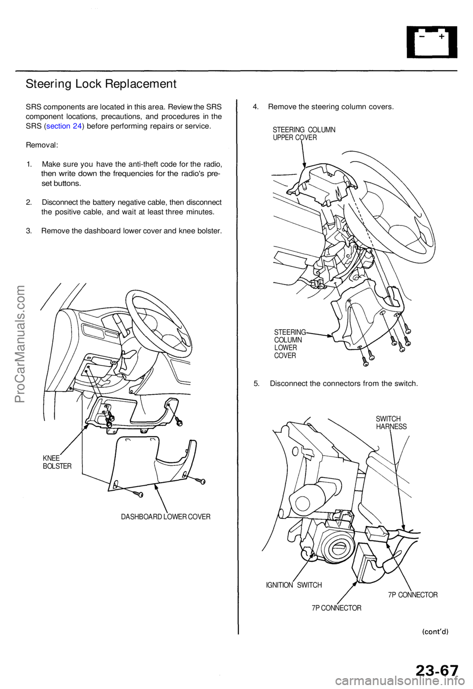
Steering Loc k Replacemen t
SRS component s ar e locate d in thi s area . Revie w th e SR S
componen t locations , precautions , an d procedure s i n th e
SR S (sectio n 24 ) befor e performin g repair s o r service .
Removal :
1 . Mak e sur e yo u hav e th e anti-thef t cod e fo r th e radio ,
then writ e dow n th e frequencie s fo r th e radio' s pre -
set buttons .
2. Disconnec t th e batter y negativ e cable , the n disconnec t
th e positiv e cable , an d wai t a t leas t thre e minutes .
3 . Remov e th e dashboar d lowe r cove r an d kne e bolster .
KNEEBOLSTE R
DASHBOARD LOWE R COVE R
4. Remov e th e steerin g colum n covers .
STEERIN G COLUM NUPPER COVE R
STEERIN GCOLUMNLOWERCOVER
5. Disconnec t th e connector s fro m th e switch .
SWITCH
HARNES S
IGNITIO N SWITC H
7 P CONNECTO R7
P CONNECTO R
ProCarManuals.com