1995 ACURA TL radio
[x] Cancel search: radioPage 862 of 1771
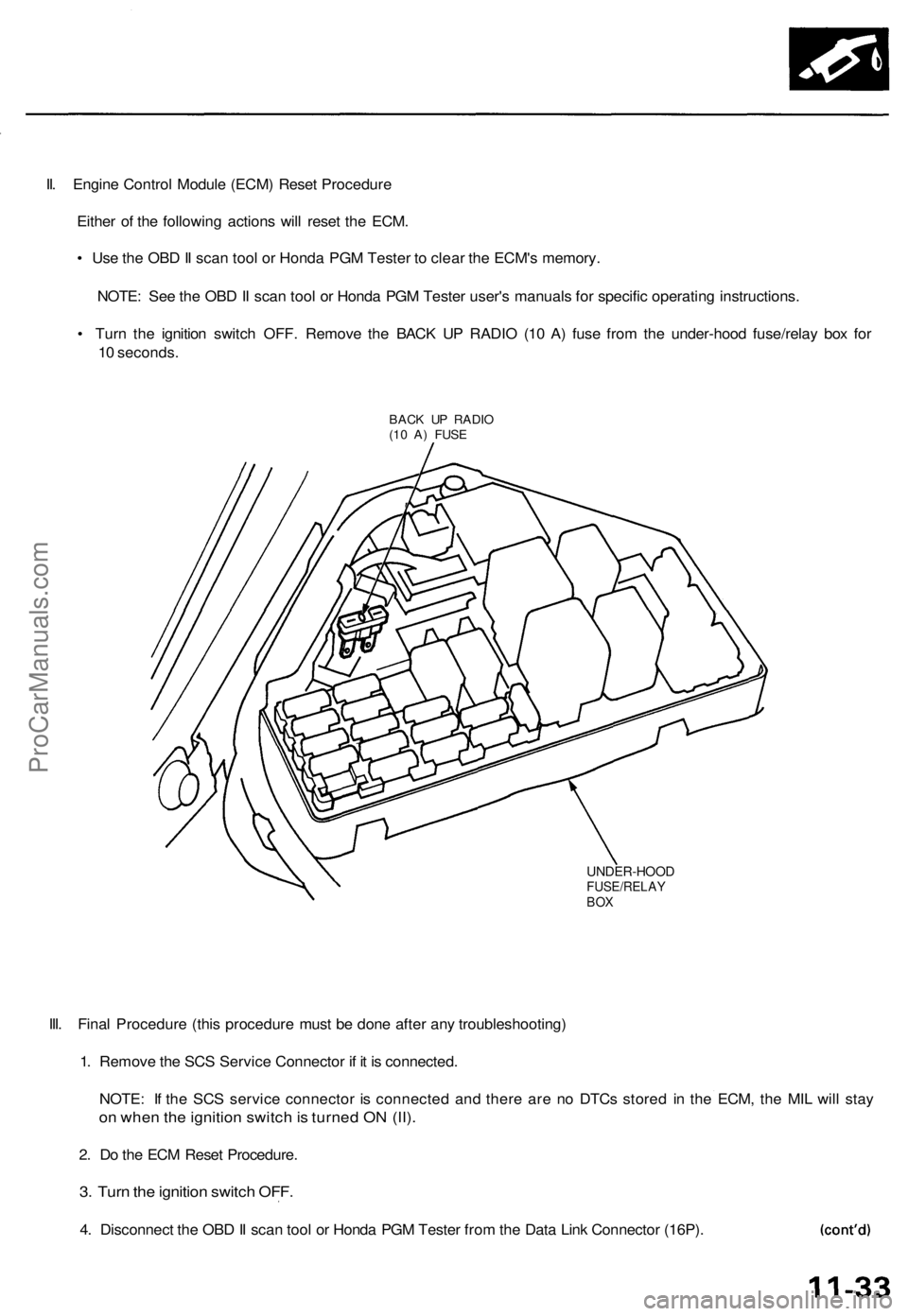
II. Engine Control Module (ECM) Reset Procedure
Either of the following actions will reset the ECM.
• Use the OBD II scan tool or Honda PGM Tester to clear the ECM's memory.
NOTE: See the OBD II scan tool or Honda PGM Tester user's manuals for specific operating instructions.
• Turn the ignition switch OFF. Remove the BACK UP RADIO (10 A) fuse from the under-hood fuse/relay box for
10 seconds.
BACK UP RADIO
(10 A) FUSE
UNDER-HOOD
FUSE/RELAY
BOX
III. Final Procedure (this procedure must be done after any troubleshooting)
1. Remove the SCS Service Connector if it is connected.
NOTE: If the SCS service connector is connected and there are no DTCs stored in the ECM, the MIL will stay
on when the ignition switch is turned ON (II).
2. Do the ECM Reset Procedure.
3. Turn the ignition switch OFF.
4. Disconnect the OBD II scan tool or Honda PGM Tester from the Data Link Connector (16P).ProCarManuals.com
Page 903 of 1771
Fuel Supply System
Fuel Pressure
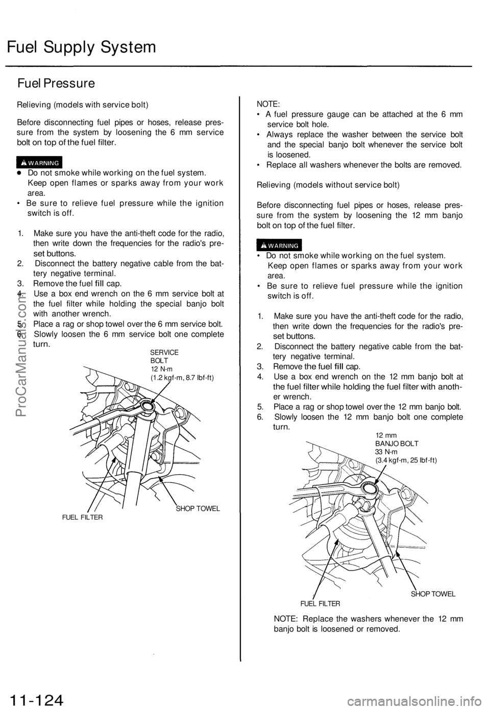
Relieving (models with service bolt)
Before disconnecting fuel pipes or hoses, release pres-
sure from the system by loosening the 6 mm service
bolt on top of the fuel filter.
Do not smoke while working on the fuel system.
Keep open flames or sparks away from your work
area.
• Be sure to relieve fuel pressure while the ignition
switch is off.
1. Make sure you have the anti-theft code for the radio,
then write down the frequencies for the radio's pre-
set buttons.
2. Disconnect the battery negative cable from the bat-
tery negative terminal.
3.
Remove
the
fuel
fill
cap.
4. Use a box end wrench on the 6 mm service bolt at
the fuel filter while holding the special banjo bolt
with another wrench.
5. Place a rag or shop towel over the 6 mm service bolt.
6. Slowly loosen the 6 mm service bolt one complete
turn.
SERVICE
BOLT
12 N-m
(1.2 kgf-m, 8.7 Ibf-ft)
SHOP TOWEL
FUEL FILTER
NOTE:
• A fuel pressure gauge can be attached at the 6 mm
service bolt hole.
• Always replace the washer between the service bolt
and the special banjo bolt whenever the service bolt
is loosened.
• Replace all washers whenever the bolts are removed.
Relieving (models without service bolt)
Before disconnecting fuel pipes or hoses, release pres-
sure from the system by loosening the 12 mm banjo
bolt on top of the fuel filter.
• Do not smoke while working on the fuel system.
Keep open flames or sparks away from your work
area.
• Be sure to relieve fuel pressure while the ignition
switch is off.
1. Make sure you have the anti-theft code for the radio,
then write down the frequencies for the radio's pre-
set buttons.
2. Disconnect the battery negative cable from the bat-
tery negative terminal.
3.
Remove
the
fuel
fill
cap.
4. Use a box end wrench on the 12 mm banjo bolt at
the fuel filter while holding the fuel filter with anoth-
er wrench.
5. Place a rag or shop towel over the 12 mm banjo bolt.
6. Slowly loosen the 12 mm banjo bolt one complete
turn.
12 mm
BANJO BOLT
33 N-m
(3.4 kgf-m, 25 Ibf-ft)
SHOP TOWEL
FUEL FILTER
NOTE: Replace the washers whenever the 12 mm
banjo bolt is loosened or removed.
11-124ProCarManuals.com
Page 910 of 1771
Fuel Filte r
Replacemen t
Do no t smok e whil e workin g o n fue l system .
Kee p ope n flam e awa y fro m you r wor k area .
• Whil e replacin g th e fue l filter , b e carefu l t o kee p a saf e
distanc e betwee n batter y terminal s an d an y tools .
Th e fue l filte r shoul d b e replace d wheneve r th e fue l pres -
sur e drop s belo w th e specifie d valu e [29 4 - 34 3 kPa ,
3. 0 - 3. 5 kgf/cm
2, 4 3 - 5 0 ps i wit h th e fue l pressur e regula -
to r vacuu m hos e disconnecte d an d pinched ] afte r makin g
sur e tha t th e fue l pum p an d th e fue l pressur e regulato r
are OK .
1. Mak e sur e yo u hav e th e anti-thef t cod e fo r th e radio ,
the n writ e dow n th e frequencie s fo r th e radio' s pre -
set buttons .
2. Disconnec t th e batter y negativ e cabl e fro m th e bat -
ter y negativ e terminal .
3 . Plac e a sho p towe l unde r an d aroun d th e fue l filter .
4 . Reliev e fue l pressur e (se e pag e 11-124 ).
5 . Remov e th e banj o bol t (model s wit h servic e bolt ) o r
1 2 m m banj o bol t (model s withou t servic e bolt ) an d
th e fue l fee d pip e whil e supportin g th e fue l filte r
wit h anothe r wrench , a s shown .
6 . Remov e th e fue l filte r clam p an d fue l filter .
7 . Instal l th e ne w fue l filte r i n th e revers e orde r of
removal , an d not e thes e items :
• Whe n assembling , us e ne w washer s a s shown .
• Clea n th e flare d join t o f hig h pressur e hose s
thoroughl y befor e reconnectin g them .
8 . Ente r th e anti-thef t cod e fo r th e radio , the n ente r th e
customer' s radi o statio n presets .
ProCarManuals.com
Page 975 of 1771

Troubleshooting Procedures
Checking the Diagnostic Trouble Code (DTC)
with an OBD II Scan tool or Honda PGM Tester
When the TCM senses an abnormality in the input or output systems, the indicator light in the gauge assembly will
blink. When the 16P Data Link Connector (DLC) (located behind the ashtray) is connected to the OBD II Scan Tool or Honda
PGM Tester as shown, the scan tool or tester will indicate the Diagnostic Trouble Code (DTC) when the ignition switch is
turned ON(II).
When the indicator light has been reported on, connect the OBD II Scan Tool conforming to SAE J1978 or Honda PGM
Tester to the DLC (16P) behind the ashtray. Turn the ignition switch on (II), and observe the DTC on the screen of the OBD II
Scan Tool or Honda PGM Tester. After determining the DTC, refer to the electrical system Symptom-to-Component Chart
on page 14-56 and 14-57.
NOTE: See the OBD II Scan Tool or Honda PGM Tester user's manual for specific instruction.
OBD II SCAN TOOL or
HONDA PGM TESTER
Some PGM-FI problems will also make the indicator light come on. After repairing the PGM-FI system, disconnect the
BACK UP RADIO fuse (10 A) in the under-hood fuse/relay box for more than 10 seconds to reset the TCM memory, then
retest.
NOTE: Disconnecting the BACK UP RADIO fuse also cancels the radio anti-theft code, preset stations and the clock setting.
Get the customer's code number, and make note of the radio presets before removing the fuse so you can reset them.
DATA LINK CONNECTOR (16P)ProCarManuals.com
Page 978 of 1771

4. Inspec t th e circui t o n th e TC M accordin g t o th e trou -
bleshootin g flowchar t wit h th e specia l tool s an d a
digita l multimete r a s shown .
How to us e th e Backprob e Se t
Connec t th e backprob e adapter s t o th e stackin g patc h
cords , an d connec t th e cord s t o a multimeter . Usin g
th e wir e insulatio n a s a guid e fo r th e contoure d ti p o f
the backprob e adapter , gentl y slid e th e ti p int o th e
connecto r fro m th e wir e sid e unti l i t come s i n contac t
with th e termina l en d o f th e wire .
BACKPROB E SE T07SAZ-001000 A
(tw o required )
BACKPROB EADAPTER
STACKIN GPATCH COR D
TCM
DIGITA L MULTIMETE R
(Commerciall y available )
KS-AHM-32-003 ,or equivalen t
TCM Rese t Procedur e
1 . Mak e sur e yo u hav e th e anti-thef t cod e fo r th e radio ,
the n writ e dow n th e frequencie s fo r th e radio' s pre -
set buttons .
2. Tur n th e ignitio n switc h OFF .
3 . Remov e th e No . 3 9 BAC K U P RADI O fus e (1 0 A )
fro m th e under-hoo d fuse/rela y bo x fo r 1 0 second s
t o rese t th e TCM .
NOTE : Th e TC M memor y canno t b e cleare d b y
usin g th e OB D II Sca n Too l o r Hond a PG M Tester ; b e
sur e to remov e th e BAC K U P RADI O fus e to rese t th e
TCM .
BACK U P RADI O
(1 0 A ) FUS E
UNDER-HOO D
FUSE/RELAYBOX
Fina l Procedur e
NOTE : Thi s procedur e mus t b e don e afte r an y trouble -
shooting.
1. Tur n th e ignitio n switc h OFF .
2 . Disconnec t th e OB D II Sca n Too l o r Hond a PG M
Teste r fro m th e Dat a Lin k Connector , o r remov e th e
specia l too l fro m th e Servic e Chec k Connector .
3. Rese t th e TCM .
4. Tur n th e ignitio n switc h O N (II) .
5 . Ente r th e anti-thef t cod e fo r th e radio , the n ente r th e
customer' s radi o statio n presets .
ProCarManuals.com
Page 1007 of 1771
Transmission
Removal
Make sur e lift s ar e place d properly , an d
hois t bracket s ar e attache d t o th e correc t positio n o n
th e engin e (se e sectio n 1 ).
CAUTION : Us e fende r cover s t o avoi d damagin g painte d
surfaces .
1. Befor e disconnectin g power , mak e sur e yo u hav e
th e anti-thef t cod e fo r th e radio , the n writ e dow n
the frequencie s fo r th e radio' s prese t buttons .
2. Disconnec t th e batter y negativ e (- ) termina l fro m
th e battery , the n remov e th e positiv e (+ ) terminal .
3 . Remov e th e batter y hold-dow n bracke t an d battery .
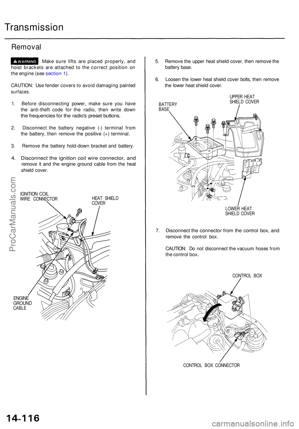
4. Disconnec t th e ignitio n coi l wir e connector , an d
remov e i t an d th e engin e groun d cabl e fro m th e hea t
shiel d cover .
IGNITIO N COI LWIRE CONNECTO R HEA
T SHIEL D
COVE R
ENGIN EGROUN DCABLE
5. Remov e th e uppe r hea t shiel d cover , the n remov e th e
batter y base .
6 . Loose n th e lowe r hea t shiel d cove r bolts , the n remov e
th e lowe r hea t shiel d cover .
BATTER YBASE
UPPE R HEA T
SHIEL D COVE R
LOWE R HEA T
SHIEL D COVE R
7. Disconnec t th e connecto r fro m th e contro l box , an d
remov e th e contro l box .
CAUTION : D o no t disconnec t th e vacuu m hose s fro m
th e contro l box .
CONTRO L BO X
CONTRO L BO X CONNECTO R
ProCarManuals.com
Page 1084 of 1771
Transmission
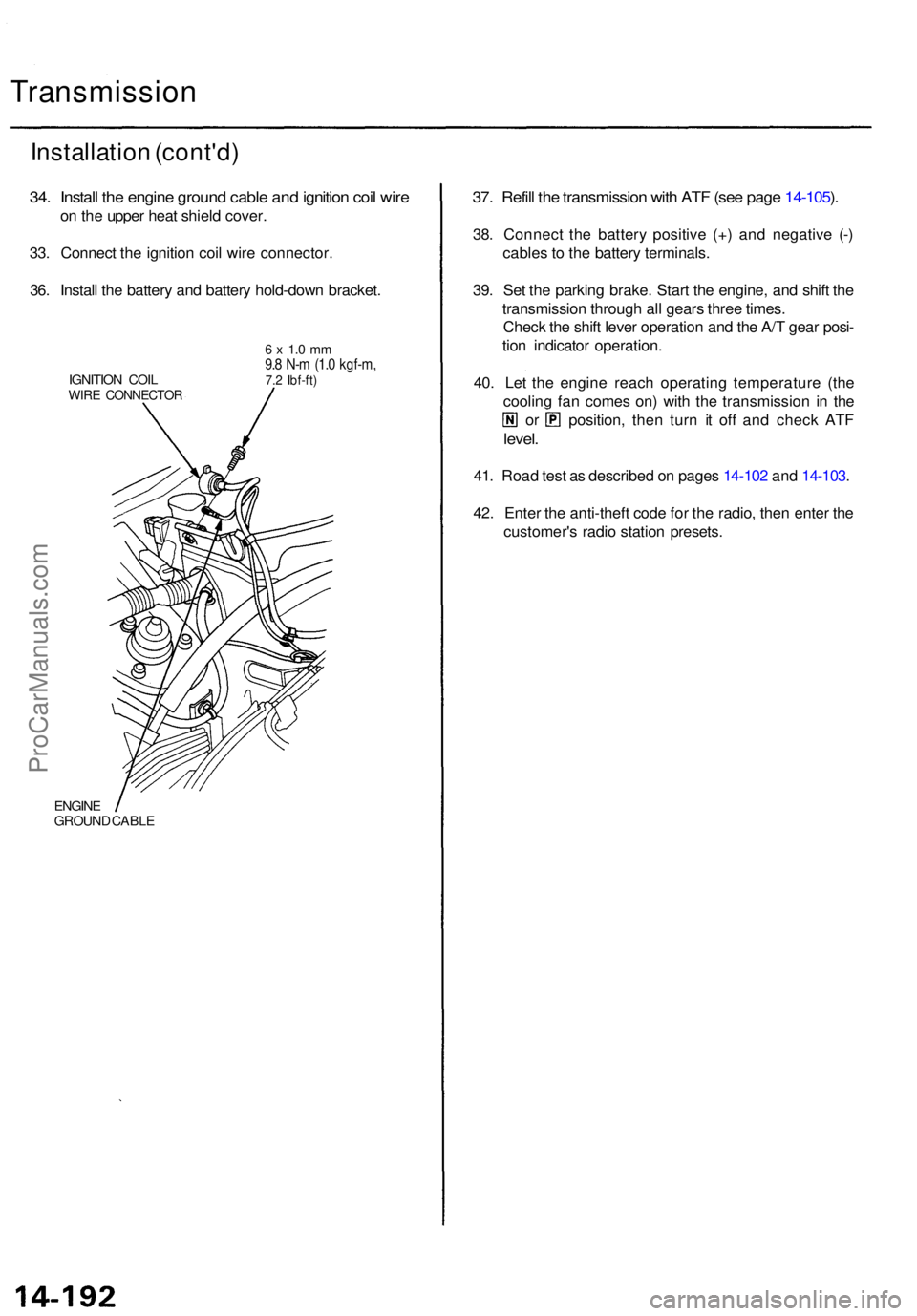
Installation (cont'd )
34. Instal l th e engin e groun d cabl e an d ignitio n coi l wir e
on th e uppe r hea t shiel d cover .
33 . Connec t th e ignitio n coi l wir e connector .
36 . Instal l th e batter y an d batter y hold-dow n bracket .
IGNITION COI LWIRE CONNECTO R
6 x 1. 0 m m9.8 N- m (1. 0 kgf-m ,7.2 Ibf-ft )
ENGIN EGROUN D CABL E
37. Refil l th e transmissio n wit h AT F (se e pag e 14-105 ).
38 . Connec t th e batter y positiv e (+ ) an d negativ e (- )
cable s t o th e batter y terminals .
39 . Se t th e parkin g brake . Star t th e engine , an d shif t th e
transmissio n throug h al l gear s thre e times .
Chec k th e shif t leve r operatio n an d th e A/ T gea r posi -
tio n indicato r operation .
40 . Le t th e engin e reac h operatin g temperatur e (th e
coolin g fa n come s on ) wit h th e transmissio n i n th e
or position , the n tur n i t of f an d chec k AT F
level .
41. Roa d tes t a s describe d o n page s 14-10 2 an d 14-103 .
42 . Ente r th e anti-thef t cod e fo r th e radio , the n ente r th e
customer' s radi o statio n presets .
ProCarManuals.com
Page 1096 of 1771
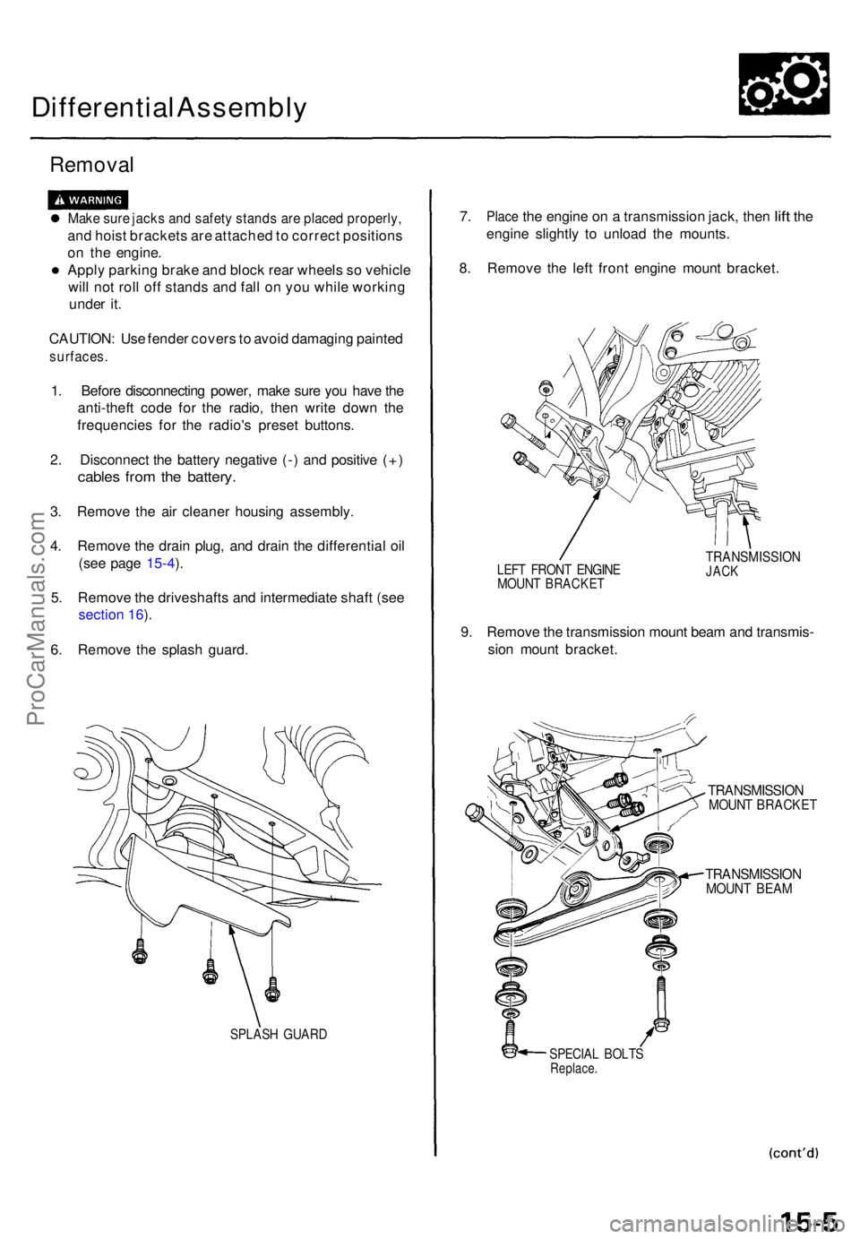
Differential Assembl y
Removal
Make sur e jack s an d safet y stand s ar e place d properly ,
and hois t bracket s ar e attache d to correc t position s
o n th e engine .
• Apply parkin g brak e an d bloc k rea r wheel s s o vehicl e
wil l no t rol l of f stand s an d fal l o n yo u whil e workin g
unde r it .
CAUTION : Us e fende r cover s to avoi d damagin g painte d
surfaces .
1. Befor e disconnectin g power , mak e sur e yo u hav e th e
anti-thef t cod e fo r th e radio , the n writ e dow n th e
frequencie s fo r th e radio' s prese t buttons .
2 . Disconnec t th e batter y negativ e (- ) an d positiv e (+ )
cable s fro m th e battery .
3. Remov e th e ai r cleane r housin g assembly .
4 . Remov e th e drai n plug , an d drai n th e differentia l oi l
(se e pag e 1 5-4 ).
5 . Remov e th e driveshaft s an d intermediat e shaf t (se e
sectio n 16 ).
6 . Remov e th e splas h guard .
SPLAS H GUAR D
7. Plac e the engin e on a transmissio n jack , the n lift th e
engin e slightl y t o unloa d th e mounts .
8 . Remov e th e lef t fron t engin e moun t bracket .
LEFT FRON T ENGIN EMOUNT BRACKE T
TRANSMISSIO NJACK
9. Remov e th e transmissio n moun t bea m an d transmis -
sio n moun t bracket .
TRANSMISSIO NMOUNT BRACKE T
TRANSMISSIO NMOUNT BEA M
SPECIA L BOLT SReplace .
ProCarManuals.com