1995 ACURA TL radio
[x] Cancel search: radioPage 223 of 1771
Fuel Pressure
Relieving
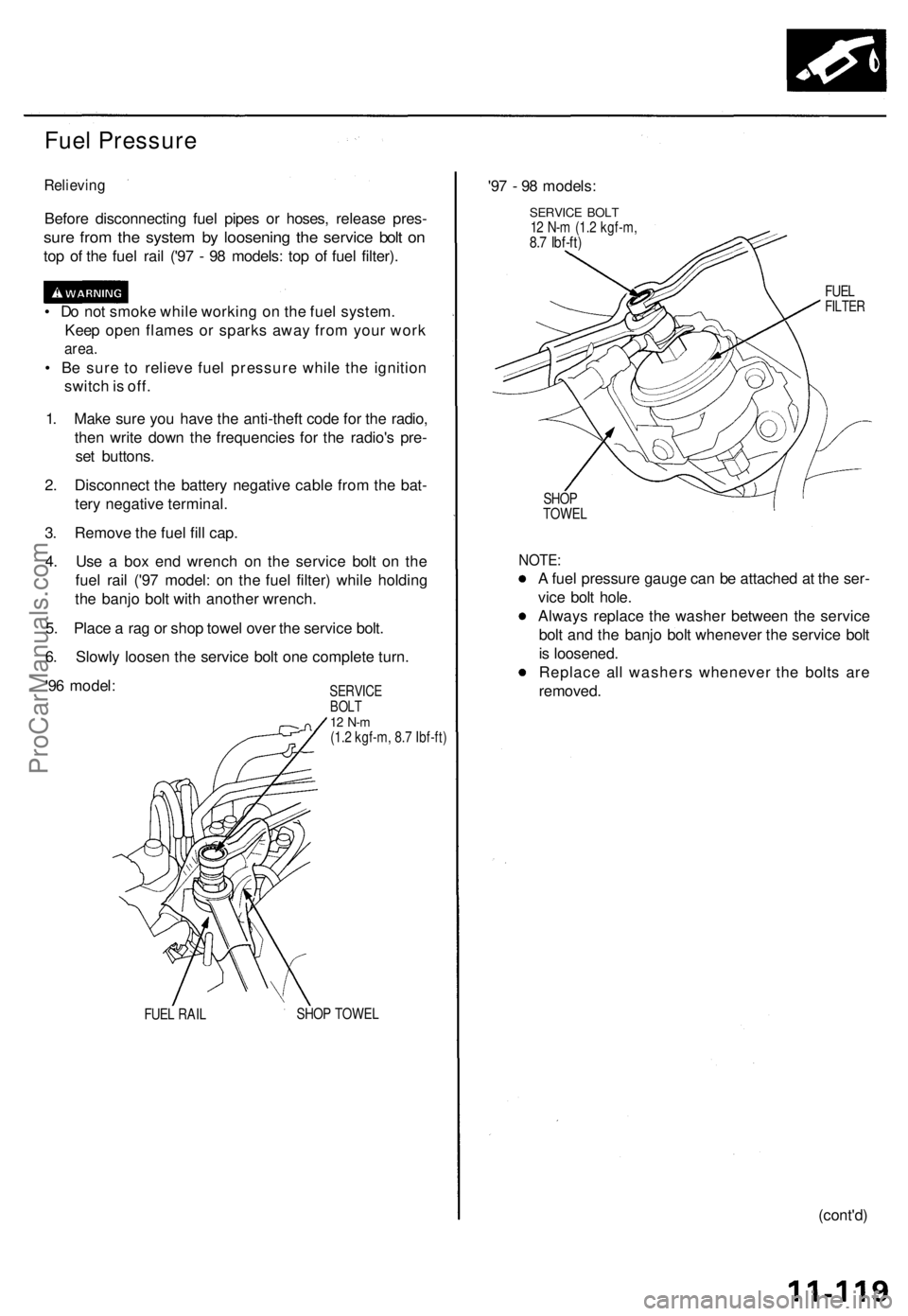
Before disconnectin g fue l pipe s o r hoses , releas e pres -
sure fro m th e syste m b y loosenin g th e servic e bol t o n
top o f th e fue l rai l ('9 7 - 9 8 models : to p o f fue l filter) .
• D o no t smok e whil e workin g o n th e fue l system .
Kee p ope n flame s o r spark s awa y fro m you r wor k
area.
• B e sur e t o reliev e fue l pressur e whil e th e ignitio n
switc h is off .
1 . Mak e sur e yo u hav e th e anti-thef t cod e fo r th e radio ,
the n writ e dow n th e frequencie s fo r th e radio' s pre -
se t buttons .
2 . Disconnec t th e batter y negativ e cabl e fro m th e bat -
ter y negativ e terminal .
3 . Remov e th e fue l fil l cap .
4 . Us e a bo x en d wrenc h o n th e servic e bol t o n th e
fue l rai l ('9 7 model : o n th e fue l filter ) whil e holdin g
th e banj o bol t wit h anothe r wrench .
5 . Plac e a ra g o r sho p towe l ove r th e servic e bolt .
6 . Slowl y loose n th e servic e bol t on e complet e turn .
'9 6 model :
SERVIC EBOLT12 N- m(1.2 kgf-m , 8. 7 Ibf-ft )
FUE L RAI L SHO
P TOWE L
'97 - 9 8 models :
SERVICE BOL T12 N- m (1. 2 kgf-m ,8.7 Ibf-ft )
FUELFILTE R
SHOP
TOWE L
NOTE:
A fue l pressur e gaug e ca n b e attache d a t th e ser -
vic e bol t hole .
Alway s replac e th e washe r betwee n th e servic e
bol t an d th e banj o bol t wheneve r th e servic e bol t
i s loosened .
Replac e al l washer s wheneve r th e bolt s ar e
removed .
(cont'd)
ProCarManuals.com
Page 232 of 1771
Fuel Filte r
Replacemen t
• D o no t smok e whil e workin g o n fue l system .
Kee p ope n flam e awa y fro m you r wor k area .
• Whil e replacin g th e fue l filter , b e carefu l t o kee p a saf e
distanc e betwee n batter y terminal s an d an y tools .
Th e fue l filte r shoul d b e replace d wheneve r th e fue l pres -
sur e drop s belo w th e specifie d valu e [26 0 - 31 0 kP a
(2.6 5 - 3.1 5 kgf/cm
2, 37. 7 - 44. 8 psi ) wit h th e fue l pressur e
regulato r vacuu m hos e disconnecte d an d pinched ] afte r
makin g sur e tha t th e fue l pum p an d th e fue l pressur e
regulato r ar e OK .
1 . Mak e sur e yo u hav e th e anti-thef t cod e fo r th e radio ,
the n writ e dow n th e frequencie s fo r th e radio' s pre -
set buttons .
2. Disconnec t th e batter y negativ e cabl e fro m th e bat -
ter y negativ e terminal .
3 . Plac e a sho p towe l unde r an d aroun d th e fue l filter .
4 . Reliev e fue l pressur e (se e pag e 11-119 ).
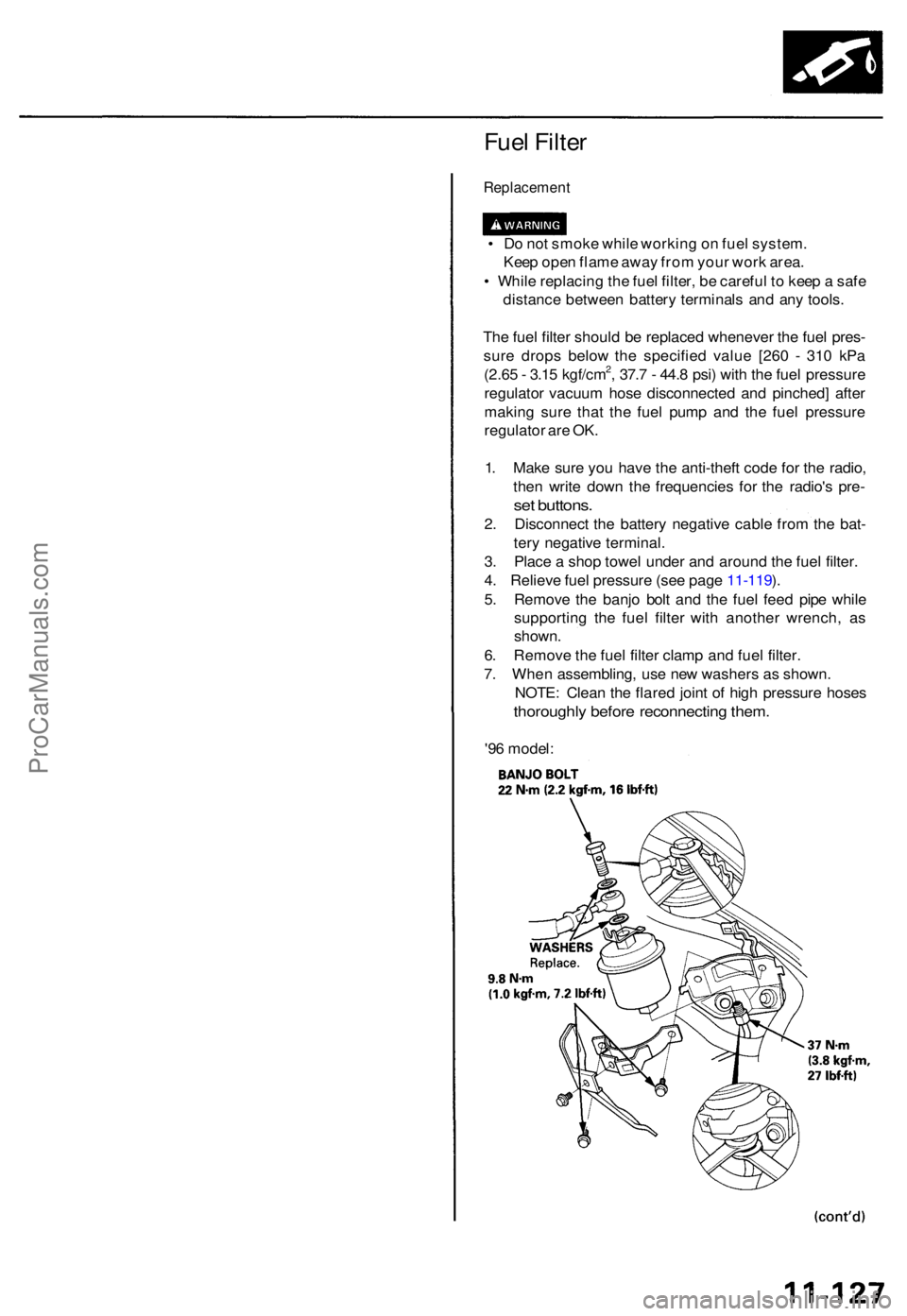
5 . Remov e th e banj o bol t an d th e fue l fee d pip e whil e
supportin g th e fue l filte r wit h anothe r wrench , a s
shown .
6 . Remov e th e fue l filte r clam p an d fue l filter .
7 . Whe n assembling , us e ne w washer s a s shown .
NOTE : Clea n th e flare d join t o f hig h pressur e hose s
thoroughl y befor e reconnectin g them .
'96 model :
ProCarManuals.com
Page 308 of 1771
PCM Reset Procedure
1. Make sure you have the anti-theft code for the radio, then write down the frequencies for the radio's preset buttons.
2. Turn the ignition switch OFF.
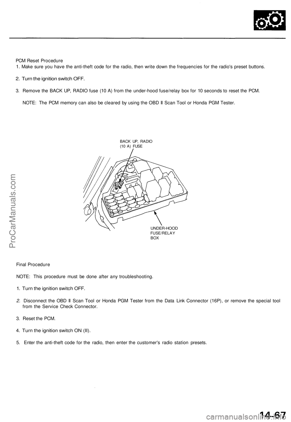
3. Remove the BACK UP, RADIO fuse (10 A) from the under-hood fuse/relay box for 10 seconds to reset the PCM.
NOTE: The PCM memory can also be cleared by using the OBD II Scan Tool or Honda PGM Tester.
BACK UP, RADIO
(10 A) FUSE
UNDER-HOOD
FUSE/RELAY
BOX
Final Procedure
NOTE: This procedure must be done after any troubleshooting.
1. Turn the ignition switch OFF.
2. Disconnect the OBD II Scan Tool or Honda PGM Tester from the Data Link Connector (16P), or remove the special tool
from the Service Check Connector.
3. Reset the PCM.
4. Turn the ignition switch ON (II).
5. Enter the anti-theft code for the radio, then enter the customer's radio station presets.ProCarManuals.com
Page 341 of 1771
Transmission
Removal
Make sur e lift s ar e place d properly , an d
hois t bracket s ar e attache d t o th e correc t positio n o n
th e engin e (se e sectio n 1 ).
CAUTION : Us e fende r cove r t o avoi d damagin g painte d
surfaces .
1. Befor e yo u disconnec t power , mak e sur e yo u hav e
th e anti-theft code fo r th e radio , the n writ e dow n
th e frequencie s fo r th e radio' s prese t buttons .
2 . Disconnec t th e batter y negativ e (- ) termina l fro m
th e battery , the n remov e th e positiv e (+ ) terminal .
3. Shif t th e transmissio n int o th e position .
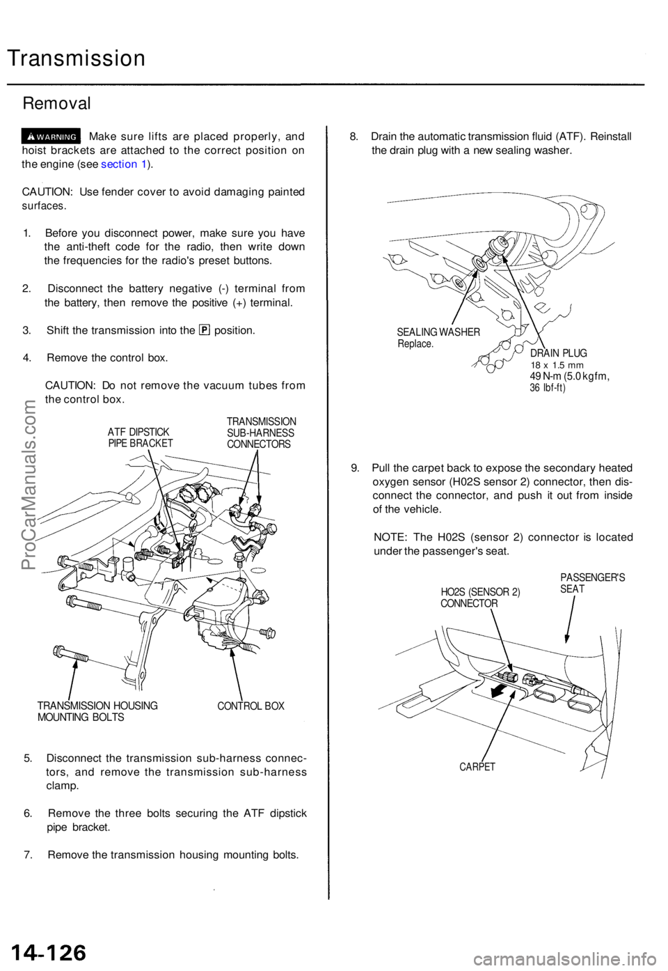
4 . Remov e th e contro l box .
CAUTION : D o no t remov e th e vacuu m tube s fro m
th e contro l box .
ATF DIPSTIC KPIPE BRACKE T
TRANSMISSIO N
SUB-HARNES S
CONNECTOR S
TRANSMISSIO N HOUSIN GMOUNTIN G BOLT SCONTRO L BO X
5. Disconnec t th e transmissio n sub-harnes s connec -
tors , an d remov e th e transmissio n sub-harnes s
clamp .
6 . Remov e th e thre e bolt s securin g th e AT F dipstic k
pip e bracket .
7 . Remov e th e transmissio n housin g mountin g bolts . 8
. Drai n th e automati c transmissio n flui d (ATF) . Reinstal l
th e drai n plu g wit h a ne w sealin g washer .
SEALIN G WASHE RReplace.DRAIN PLU G18 x 1. 5 m m49 N- m (5. 0 kgfm ,36 Ibf-ft )
9. Pul l th e carpe t bac k t o expos e th e secondar y heate d
oxyge n senso r (H02 S senso r 2 ) connector , the n dis -
connec t th e connector , an d pus h i t ou t fro m insid e
o f th e vehicle .
NOTE : Th e H02 S (senso r 2 ) connecto r i s locate d
unde r th e passenger' s seat .
HO2S (SENSO R 2 )
CONNECTO R PASSENGER'
SSEAT
CARPE T
ProCarManuals.com
Page 428 of 1771
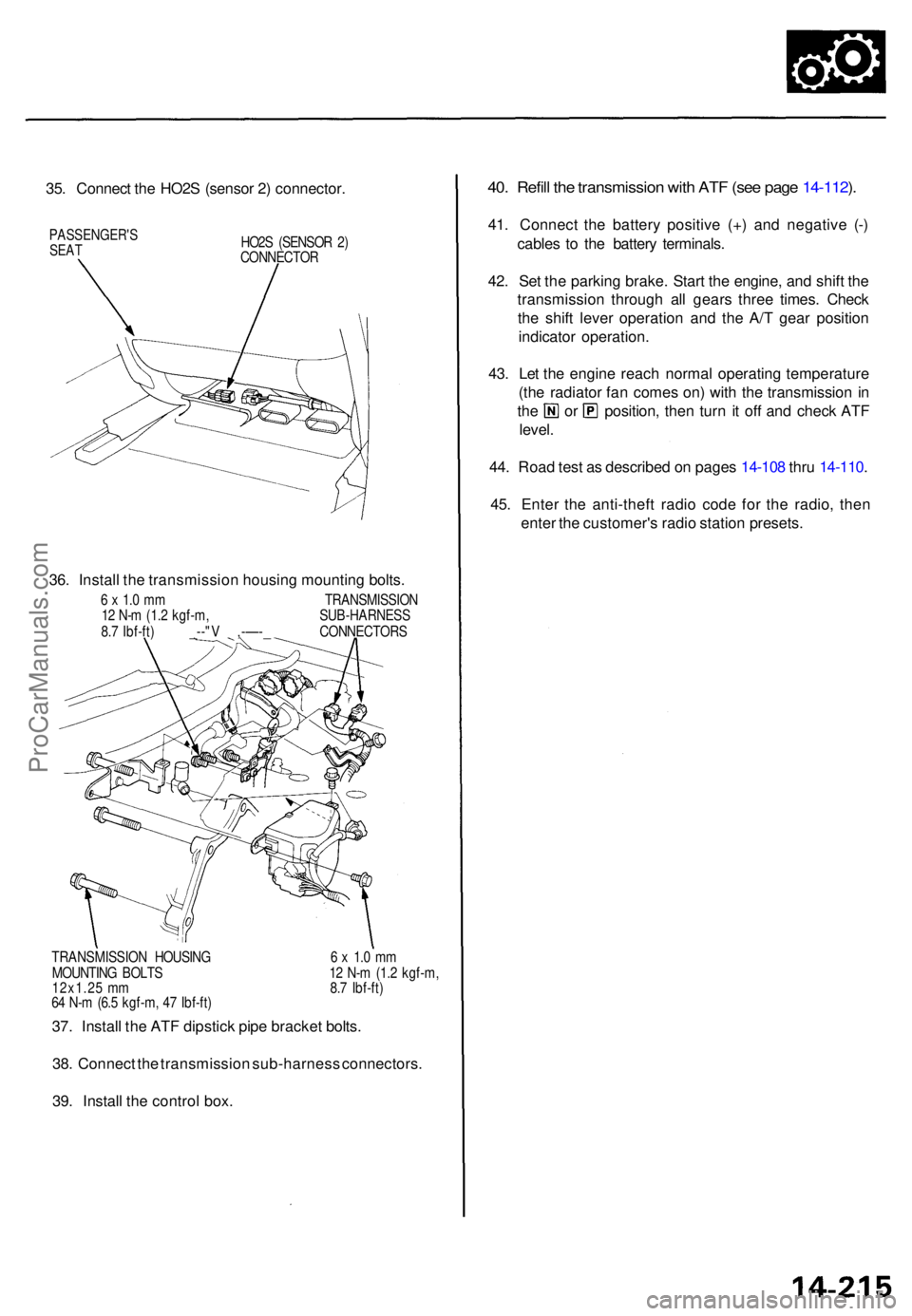
35. Connec t th e HO2 S (senso r 2 ) connector .
PASSENGER' SSEATHO2S (SENSO R 2 )
CONNECTO R
36. Instal l th e transmissio n housin g mountin g bolts .
6 x 1. 0 m m TRANSMISSIO N
1 2 N- m (1. 2 kgf-m , SUB-HARNES S
8. 7 Ibf-ft ) _--" V ,-—- _ CONNECTOR S
TRANSMISSIO N HOUSIN G 6 x 1. 0 m m
MOUNTIN G BOLT S 1 2 N- m (1. 2 kgf-m ,
12x1.2 5 m m 8. 7 Ibf-ft )
6 4 N- m (6. 5 kgf-m , 4 7 Ibf-ft )
37. Instal l th e AT F dipstic k pip e bracke t bolts .
38 . Connec t th e transmissio n sub-harnes s connectors .
39 . Instal l th e contro l box .
40. Refil l th e transmissio n wit h AT F (se e pag e 14-112 ).
41 . Connec t th e batter y positiv e (+ ) an d negativ e (- )
cable s t o th e batter y terminals .
42 . Se t th e parkin g brake . Star t th e engine , an d shif t th e
transmissio n throug h al l gear s thre e times . Chec k
th e shif t leve r operation and th e A/ T gea r positio n
indicato r operation .
43 . Le t th e engin e reac h norma l operatin g temperatur e
(th e radiato r fa n come s on ) wit h th e transmissio n in
th e o r position , the n tur n i t of f an d chec k AT F
level .
44 . Roa d tes t a s describe d o n page s 14-10 8 thr u 14-110 .
45 . Ente r th e anti-thef t radi o cod e fo r th e radio , the n
ente r th e customer' s radi o statio n presets .
ProCarManuals.com
Page 508 of 1771

Troubleshooting Precautions
ABS Indicator Light:
The ABS indicator light comes on for three seconds and then goes off when the control unit detects no problem during the
initial diagnosis right after the engine starts. However, the ABS indicator light can stay on for up to 40 seconds when the
control unit starts to check for pump overrun, etc. during the initial diagnosis. The ABS indicator light comes on, and the
ABS control unit memorizes the diagnostic trouble code (DTC) under certain conditions.
• The parking brake is applied for more than 30 seconds while the vehicle is being driven. (DTC 2-1)
• The transmission downshifted excessively. (DTC 4-1, 4-2)
• The vehicle loses traction, and the front wheels spin for more than one minute when starting from a stuck condition on
a muddy, snowy, or sandy road. (DTC 4-8)
• Tire adhesion is lost due to excessive cornering speed. (DTC 5, 5-4, 5-8)
• The vehicle is driven on an extremely rough road. (DTC 8-1)
• The vehicle is interfered by strong radio waves (noise), for example, illegal radio, etc. (DTC 8-2)
NOTE: If there is any trouble in the system, the ABS indicator light comes on during driving.
Diagnostic Trouble Code (DTC):
• When the control unit detects a problem and the ABS indicator light comes on, the control unit memorizes the DTC.
• The control unit has three memory registers. When a problem occurs, the control unit stores the DTC in the first memory
register. If another problem occurs, or the same problem occurs again, the control unit moves the first DTC to the next
memory register, and stores the second DTC in the first register. If there's a third problem occurrence, the two existing
DTCs are moved up one register, and the third DTC is stored in the first register. If problems continue to occur, the oldest
problem is moved out of the last register and lost, and the most recent problem is stored in the first register. When the
same problem occurs three times, the same DTC is stored in all memory registers. (Refer to the Symptom-to-System
Chart for diagnostic period.)
• The most recent DTC is indicated first, and the oldest DTC is indicated last.
• The DTCs are erased from the control unit when the ABS control unit +B2 power supply or connector is disconnected.
• The control unit's memory can be erased by disconnecting the ABS B2 fuse for more than three seconds.
Self-diagnosis:
• There are three self-diagnosises described below.
Initial diagnosis: Performed right after the engine starts until the ABS indicator light goes off.
Regular diagnosis: Continuously performed (under some conditions) after the ABS indicator light goes off until the
engine stops.
Individual part/system diagnosis: Diagnosis about a specific part/system under its operating conditions.
• The CPU (central processing unit) controls the following when it detects a problem during self-diagnosis:
Turns the ABS indicator light ON.
Turns the front and rear fail-safe relays off.
Stops the ABS control.
Stops the ABS pump. (The pump may work under some conditions.)
After the DTC is stored in the control unit, the CPU stops self-diagnosis.ProCarManuals.com
Page 564 of 1771
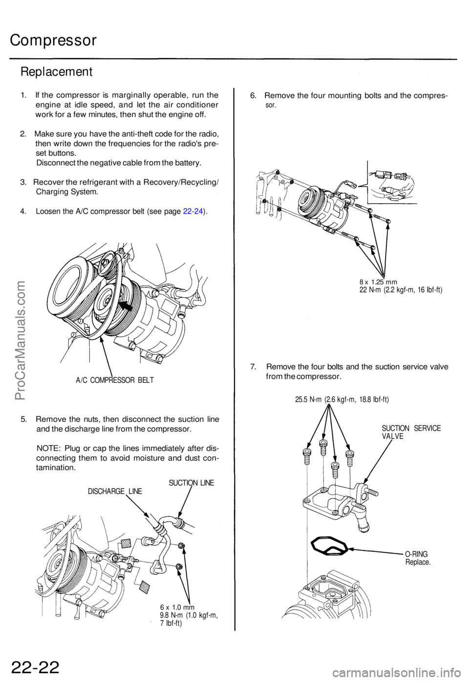
Compressor
Replacemen t
1. I f th e compresso r i s marginall y operable , ru n th e
engin e a t idl e speed , an d le t th e ai r conditione r
wor k fo r a fe w minutes , the n shu t th e engin e off .
2 . Mak e sur e yo u hav e th e anti-thef t cod e fo r th e radio ,
the n writ e dow n th e frequencie s fo r th e radio' s pre -
se t buttons .
Disconnec t th e negativ e cabl e fro m th e battery .
3 . Recove r th e refrigeran t wit h a Recovery/Recycling /
Charging System .
4. Loose n th e A/ C compresso r bel t (se e pag e 22-24 ).
A/ C COMPRESSO R BEL T
5. Remov e th e nuts , the n disconnec t th e suctio n lin e
an d th e discharg e lin e fro m th e compressor .
NOTE : Plu g o r cap the line s immediatel y afte r dis -
connectin g the m to avoi d moistur e an d dus t con -
tamination .
SUCTION LIN EDISCHARG E LIN E
6 x 1. 0 m m9.8 N- m (1. 0 kgf-m ,
7 Ibf-ft )
6. Remov e th e fou r mountin g bolt s an d th e compres -
sor.
8 x 1.2 5 mm22 N- m (2. 2 kgf-m , 1 6 Ibf-ft )
7. Remov e th e fou r bolt s an d th e suctio n servic e valv e
fro m th e compressor .
25.5 N- m (2. 6 kgf-m , 18. 8 Ibf-ft )
SUCTIO N SERVIC E
VALVE
O-RIN G
Replace .
22-22ProCarManuals.com
Page 565 of 1771
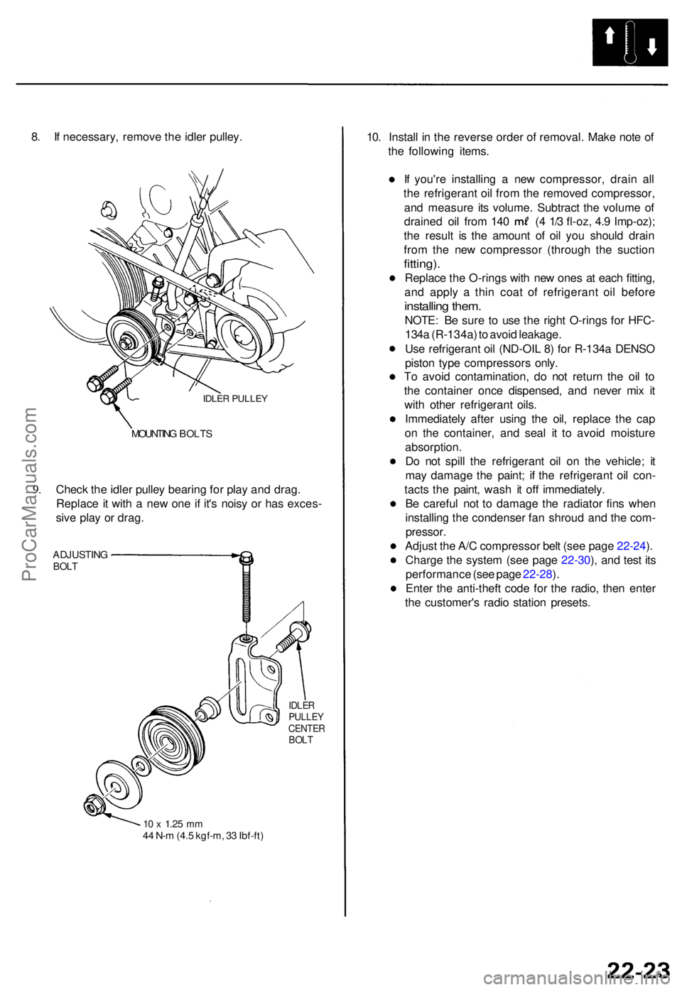
8. I f necessary , remov e th e idle r pulley .
IDLER PULLE Y
9.
MOUNTIN G BOLT S
Check th e idle r pulle y bearin g fo r pla y an d drag .
Replac e it wit h a ne w on e i f it' s nois y o r ha s exces -
siv e pla y o r drag .
ADJUSTIN GBOLT
IDLE RPULLE YCENTE RBOLT
10 x 1.2 5 mm44 N- m (4. 5 kgf-m , 3 3 Ibf-ft )
10. Instal l i n th e revers e orde r o f removal . Mak e not e o f
th e followin g items .
I f you'r e installin g a ne w compressor , drai n al l
th e refrigeran t oi l fro m th e remove d compressor ,
an d measur e it s volume . Subtrac t th e volum e o f
draine d oi l fro m 14 0 ( 4 1/ 3 fl-oz , 4. 9 Imp-oz) ;
th e resul t i s th e amoun t o f oi l yo u shoul d drai n
fro m th e ne w compresso r (throug h th e suctio n
fitting).
Replac e th e O-rings with ne w one s a t eac h fitting ,
an d appl y a thi n coa t of refrigeran t oi l befor e
installin g them .
NOTE : B e sur e t o us e th e righ t O-ring s fo r HFC -
134 a (R-134a ) t o avoi d leakage .
Us e refrigeran t oi l (ND-OI L 8 ) fo r R-134 a DENS O
pisto n typ e compressor s only .
T o avoi d contamination , d o no t retur n th e oi l t o
th e containe r onc e dispensed , an d neve r mi x i t
wit h othe r refrigeran t oils .
Immediatel y afte r usin g th e oil , replac e th e ca p
o n th e container , an d sea l i t t o avoi d moistur e
absorption .
D o no t spil l th e refrigeran t oi l o n th e vehicle ; i t
ma y damag e th e paint ; i f th e refrigeran t oi l con -
tact s th e paint , was h i t of f immediately .
B e carefu l no t t o damag e th e radiato r fin s whe n
installin g th e condense r fa n shrou d an d th e com -
pressor .
Adjust th e A/ C compresso r bel t (se e pag e 22-24 ).
Charg e th e syste m (se e pag e 22-30 ), an d tes t it s
performanc e (se e pag e 22-28 ).
Ente r th e anti-thef t cod e fo r th e radio , the n ente r
th e customer' s radi o statio n presets .
ProCarManuals.com