Page 1278 of 1771

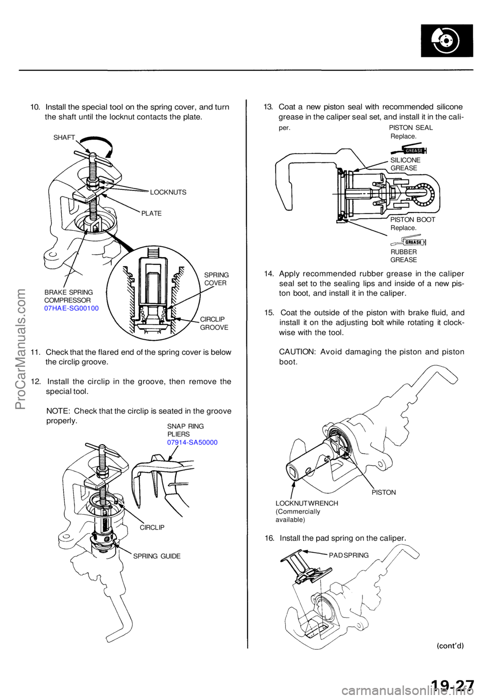
10. Instal l th e specia l too l o n th e sprin g cover , an d tur n
the shaf t unti l th e locknu t contact s th e plate .
SHAF T
LOCKNUT S
BRAKE SPRIN GCOMPRESSO R07HAE-SG0010 0 SPRIN
G
COVER
CIRCLI PGROOV E
11. Chec k tha t th e flare d en d o f th e sprin g cove r i s belo w
th e circli p groove .
12 . Instal l th e circli p i n th e groove , the n remov e th e
specia l tool .
NOTE : Chec k tha t th e circli p is seated in th e groov e
properly .
13. Coa t a ne w pisto n sea l wit h recommende d silicon e
grease in th e calipe r sea l set , an d instal l i t i n th e cali -
per. PISTO N SEA LReplace .
RUBBERGREAS E
14. Appl y recommende d rubbe r greas e i n th e calipe r
sea l se t t o th e sealin g lip s an d insid e o f a ne w pis -
to n boot , an d instal l i t i n th e caliper .
15 . Coa t th e outsid e o f th e pisto n wit h brak e fluid , an d
instal l i t o n th e adjustin g bol t whil e rotatin g i t clock -
wis e wit h th e tool .
CAUTION : Avoi d damagin g th e pisto n an d pisto n
boot.
PISTO N
LOCKNU T WRENC H
(Commerciall y
available)
16. Instal l th e pa d sprin g o n th e calipe r
PAD SPRIN G
PLATE
SILICON EGREASE
PISTON BOO TReplace .
CIRCLIP
SPRING GUID E
SNA
P RIN G
PLIER S07914-SA5000 0
ProCarManuals.com
Page 1404 of 1771

Opening Dra g Chec k
(Motor Removed )
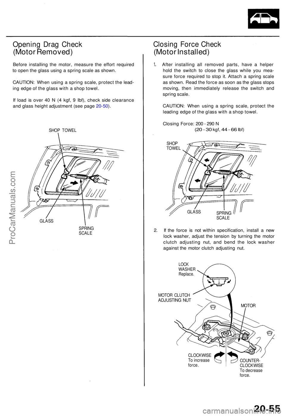
Before installin g th e motor , measur e th e effor t require d
t o ope n th e glas s usin g a sprin g scal e a s shown .
CAUTION : Whe n usin g a sprin g scale , protec t th e lead -
in g edg e o f th e glas s wit h a sho p towel .
I f loa d i s ove r 4 0 N (4 kgf , 9 Ibf) , chec k sid e clearanc e
an d glas s heigh t adjustmen t (se e pag e 20-50 ).
SHO P TOWE L
GLAS S
SPRING
SCAL E
Closin g Forc e Chec k
(Moto r Installed )
1. Afte r installin g al l remove d parts , hav e a helpe r
hol d th e switc h t o clos e th e glas s whil e yo u mea -
sur e forc e require d t o sto p it . Attac h a sprin g scal e
a s shown . Rea d th e forc e a s soo n a s th e glas s stop s
moving , the n immediatel y releas e th e switc h an d
sprin g scale .
CAUTION : Whe n usin g a sprin g scale , protec t th e
leadin g edg e o f th e glas s wit h a sho p towel .
Closin g Force : 20 0 - 29 0 N
(2 0 - 3 0 kgf , 44 - 6 6 Ibf )
SHO P
TOWE L
SPRING
SCALE
2. I f th e forc e i s no t withi n specification , instal l a ne w
loc k washer , adjus t th e tensio n b y turnin g th e moto r
clutc h adjustin g nut , an d ben d th e loc k washe r
agains t th e moto r clutc h adjustin g nut .
LOC KWASHE RReplace .
MOTOR CLUTC HADJUSTIN G NU T
CLOCKWIS ETo increas eforce.COUNTER -CLOCKWIS ETo decreas e
force .
MOTO R
GLASS
ProCarManuals.com
Page 1413 of 1771
Carpet
Replacemen t
SRS component s ar e locate d in thi s area . Revie w th e SR S
componen t locations , precautions , an d procedure s i n th e
SR S (sectio n 24 ) befor e performin g repair s o r service .
1 . Remove :
Fron t sea t (se e pag e 20-71 )
Rea r sea t cushio n (se e pag e 20-85 )
Fron t doo r sil l moldin g (se e pag e 20-57 )
Rea r doo r sil l moldin g (se e pag e 20-57 )
Fron t sea t bel t lowe r ancho r (se e pag e 20-88 )
Cente r pilla r lowe r tri m (se e pag e 20-57 )
Cente r consol e (se e pag e 20-64 )
Dashboar d cente r tri m (se e pag e 20-67 )
Opene r cove r (se e pag e 20-115 )
2 . Remov e th e accelerato r peda l sto p an d footrest .
NOTE : Loose n th e clip s usin g a he x wrenc h b y
turnin g the m counterclockwise .
6 x 1. 0 m m9.8 N- m (1. 0 kgf-m ,
7. 2 Ibf-ft )
3. Cu t are a i n th e carpet , the n pul l i t bac k a s shown .
CARPE T
FASTENE RSRS UNI T
FOOTRES T
ACCELERATO RPEDAL STO PCLIP
ProCarManuals.com
Page 1416 of 1771

Dashboard
Componen t Removal/Installatio n
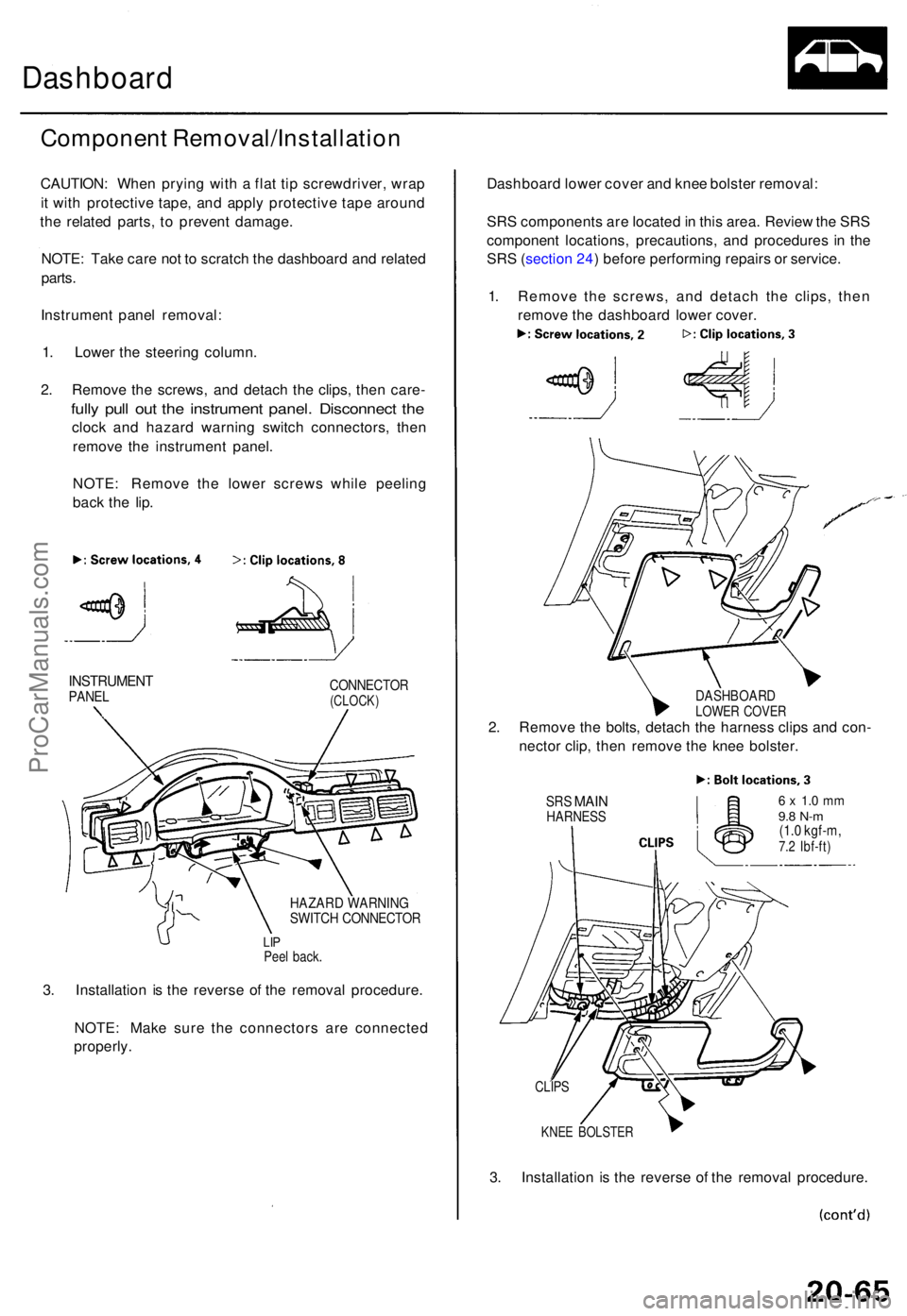
CAUTION: Whe n pryin g wit h a fla t ti p screwdriver , wra p
i t wit h protectiv e tape , an d appl y protectiv e tap e aroun d
th e relate d parts , t o preven t damage .
NOTE : Tak e car e no t t o scratc h th e dashboar d an d relate d
parts .
Instrumen t pane l removal :
1 . Lowe r th e steerin g column .
2 . Remov e th e screws , an d detac h th e clips , the n care -
fully pul l ou t th e instrumen t panel . Disconnec t th e
cloc k an d hazar d warnin g switc h connectors , the n
remov e th e instrumen t panel .
NOTE : Remov e th e lowe r screw s whil e peelin g
bac k th e lip .
INSTRUMEN TPANELCONNECTO R(CLOCK)
HAZARD WARNIN GSWITCH CONNECTO R
LIPPee l back .
3. Installatio n i s th e revers e o f th e remova l procedure .
NOTE : Mak e sur e th e connector s ar e connecte d
properly . Dashboar
d lowe r cove r an d kne e bolste r removal :
SR S component s ar e locate d in thi s area . Revie w th e SR S
componen t locations , precautions , an d procedure s i n th e
SR S (sectio n 24 ) befor e performin g repair s o r service .
1 . Remov e th e screws , an d detac h th e clips , the n
remov e th e dashboar d lowe r cover .
DASHBOAR DLOWER COVE R2. Remov e th e bolts , detac h th e harnes s clip s an d con -
necto r clip , the n remov e th e kne e bolster .
SRS MAI NHARNES S6 x 1. 0 m m9.8 N- m(1.0 kgf-m ,7.2 Ibf-ft )
KNEE BOLSTE R
3. Installatio n i s th e revers e o f th e remova l procedure .
CLIPS
ProCarManuals.com
Page 1636 of 1771

Lighting Syste m
Front Parkin g Ligh t
Combinatio n Ligh t Switc h
Replacemen t
SRS component s ar e locate d i n thi s area . Revie w th e
SR S componen t locations , precautions , an d procedure s
i n th e SR S (sectio n 24 ) befor e performin g repair s o r ser -
vice .
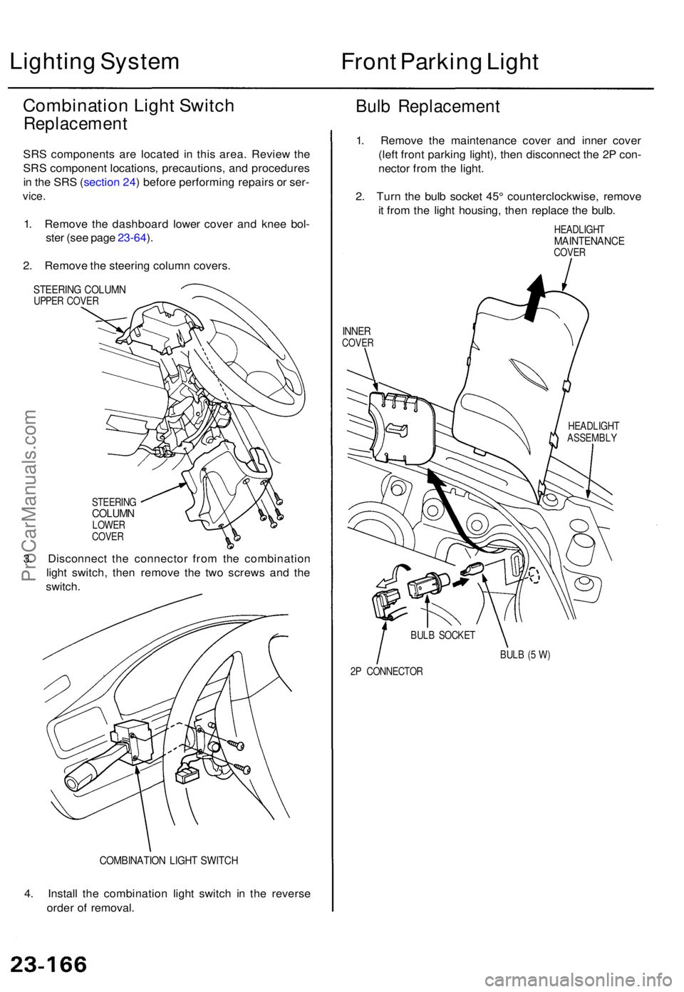
1. Remov e th e dashboar d lowe r cove r an d kne e bol -
ste r (se e pag e 23-64 ).
2 . Remov e th e steerin g colum n covers .
STEERIN G COLUM NUPPER COVE R
Bulb Replacemen t
STEERINGCOLUMNLOWER
COVE R
3. Disconnec t th e connecto r fro m th e combinatio n
ligh t switch , the n remov e th e tw o screw s an d th e
switch .
COMBINATIO N LIGH T SWITC H
4. Instal l th e combinatio n ligh t switc h i n th e revers e
orde r o f removal . 1
. Remov e th e maintenanc e cove r an d inne r cove r
(lef t fron t parkin g light) , the n disconnec t th e 2 P con -
necto r fro m th e light .
2 . Tur n th e bul b socke t 45 ° counterclockwise , remov e
i t fro m th e ligh t housing , the n replac e th e bulb .
HEADLIGH TMAINTENANC ECOVER
INNERCOVE R
HEADLIGH T
ASSEMBL Y
BUL B (5 W )
2 P CONNECTO R
BUL
B SOCKE T
ProCarManuals.com
Page 1641 of 1771
Front Tur n Signa l Light s Fron
t Sid e Marke rLights
Replacemen t
1. Remov e th e screw , an d pul l th e fron t tur n signa l
ligh t assembl y ou t o f th e fron t bumper .
FRONT TUR N
SIGNA L LIGH T
2P CONNECTO R
2. Disconnec t th e 2 P connecto r fro m th e light .
3. Tur n th e bul b socke t 45 ° counterclockwise , remov e
it fro m th e ligh t housing , the n replac e th e bulb .
BULB(21 W )
HOUSIN G
BULB SOCKE T
Replacemen t
1. Remov e th e screw , an d pul l th e fron t sid e marke r
light assembl y ou t o f th e fron t bumper .
FRONT SID E MARKE R LIGH T
2P CONNECTO R
2. Disconnec t th e 2 P connecto r fro m th e light .
3. Tur n th e bul b socke t 45 ° counterclockwise , remov e
i t fro m th e ligh t housing , the n replac e th e bulb .
HOUSIN GBULB(3CP)
BULB SOCKE T
ProCarManuals.com
Page 1642 of 1771
Taillights
Replacemen t
1. Ope n th e trun k lid , an d pul l bac k th e trun k sid e trim .
2. Disconnec t th e 8 P connecto r fro m th e tailligh t
assembly .
3. Remov e th e fou r mountin g nut s an d th e tailligh t
assembly .
GASKET
8P CONNECTO RTAILLIGHTASSEMBL Y
NOTE:
Inspect the gasket; replace it if it is distorted or stays
compressed .
After installin g them , ru n wate r ove r th e light s t o
mak e sur e the y d o no t leak .
Bulb Replacemen t
1. Ope n th e trun k lid , an d pul l bac k th e trun k sid e trim .
2 . Tur n th e bul b socke t 45 ° counterclockwise , remov e
it fro m th e tailligh t housing , the n replac e th e bulb .
BRAK E LIGHT/TAILLIGH T BUL B (21/ 5 W )
REA R SID E MARKE R LIGH T BUL B (3CP )
TURN SIGNA L LIGH T BUL B (2 1 W )
BACK-U P LIGH T BUL B (2 1 W )
ProCarManuals.com
Page 1643 of 1771
License Plate Lights
A/T Gear Position
Indicator Trim Light
Replacement
1. Remove the two screws from the license plate light
assembly.
2. Pull the light out, and disconnect the 2P connector
from it.
2P CONNECTOR
LENS
BULB (8 W)
3. Take the lens off, then replace the bulb.
Replacement
1. Carefully pry the A/T gear position indicator trim out
of the center console.
A/T GEAR POSITION INDICATOR TRIM
CENTER CONSOLE
2. Turn the 2P connector counterclockwise to remove
it from the A/T gear position indicator trim.
3. Remove the bulb from the 2P connector.
A/T GEAR
POSITION
INDICATOR
TRIM
BULB (1.4 W)
2P CONNECTORProCarManuals.com