1995 ACURA TL clock
[x] Cancel search: clockPage 62 of 1771
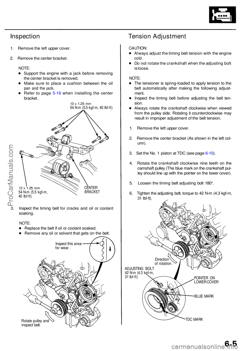
InspectionTension Adjustmen t
1. Remov e th e lef t uppe r cover .
2 . Remov e th e cente r bracket .
NOTE:
Suppor t th e engin e wit h a jac k befor e removin g
th e cente r bracke t i s removed .
Mak e sur e t o plac e a cushio n betwee n th e oi l
pan an d th e jack .
Refe r t o pag e 5-1 6 whe n installin g th e cente r
bracket .
10 x 1.2 5 mm54 N- m (5. 5 kgf-m , 4 0 Ibf-ft )
12 x 1.2 5 mm54 N- m (5. 5 kgf-m ,
4 0 Ibf-ft ) CENTE
RBRACKE T
3. Inspec t th e timin g bel t fo r crack s an d oi l o r coolan t
soaking .
NOTE:
Replac e th e bel t i f oi l o r coolan t soaked .
Remov e an y oi l o r solven t tha t get s o n th e belt .
Inspec t thi s area -for wear .
Rotate pulle y an dinspec t belt .
CAUTION :
Always adjus t th e timin g bel t tensio n wit h th e engin e
cold.
Do no t rotat e th e crankshaf t whe n th e adjustin g bol t
i s loose .
NOTE :
The tensione r i s spring-loade d t o appl y tensio n t o th e
bel t automaticall y afte r makin g th e followin g adjust -
ment .
Inspec t th e timin g bel t befor e adjustin g th e bel t ten -
sion .
Alway s rotat e th e crankshaf t clockwis e whe n viewe d
fro m th e pulle y side . Rotatin g it counterclockwis e ma y
resul t i n imprope r adjustmen t o f th e bel t tension .
1 . Remov e th e lef t uppe r cover .
2 . Remov e th e cente r bracke t (A s show n in th e lef t col -
umn) .
3. Se t th e No . 1 pisto n a t TD C (se e pag e 6-10 ).
4 . Rotat e th e crankshaf t clockwis e nin e teet h o n th e
camshaf t pulle y (Th e blu e mar k o n th e crankshaf t pul -
le y shoul d lin e u p wit h th e pointe r o n th e lowe r cover) .
5 . Loose n th e timin g bel t adjustin g bol t 180° .
6 . Tighte n th e adjustin g bolt , torqu e to 4 2 N- m (4. 3 kgf-m ,
31 Ibf-ft) .
ADJUSTIN G BOL T
4 2 N- m (4. 3 kgf-m ,
3 1 Ibf-ft )
BLUE MAR K
TD C MAR K
POINTE
R O N
LOWE R COVE R
Directio nof rotation .
ProCarManuals.com
Page 67 of 1771
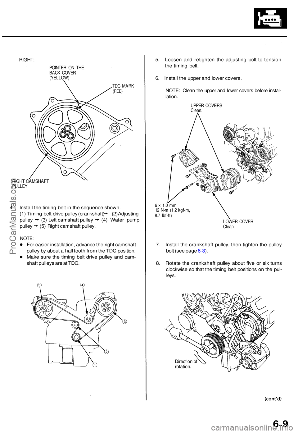
RIGHT:
POINTE R O N TH E
BAC K COVE R
(YELLOW )
TDC MAR K(RED)
RIGHT CAMSHAF TPULLEY
4. Instal l th e timin g bel t i n th e sequenc e shown .
(1) Timin g bel t driv e pulle y (crankshaft ) (2 ) Adjustin g
pulley (3 ) Lef t camshaf t pulle y (4) Wate r pum p
pulley (5) Right camshaf t pulley .
NOTE:
For easie r installation , advanc e th e righ t camshaf t
pulle y b y abou t a hal f toot h fro m th e TD C position .
Mak e sur e th e timin g bel t driv e pulle y an d cam -
shaf t pulley s ar e a t TDC . 5
. Loose n an d retighte n th e adjustin g bol t t o tensio n
th e timin g belt .
6 . Instal l th e uppe r an d lowe r covers .
NOTE: Clea n th e uppe r an d lowe r cover s befor e instal -
lation.
UPPE R COVER S
Clean .
6 x 1. 0 m m12 N- m (1. 2 kgf- m
8. 7 Ibf-ft )
LOWER COVE R
Clean .
7. Instal l th e crankshaf t pulley , the n tighte n th e pulle y
bol t (se e pag e 6-3 ).
8 . Rotat e th e crankshaf t pulle y abou t fiv e o r si x turn s
clockwis e s o tha t th e timin g bel t position s o n th e pul -
leys .
Directio n o frotation .
ProCarManuals.com
Page 92 of 1771
Reaming
NOTE: Fo r ne w valv e guide s only .
1 . Coa t bot h th e reame r an d valv e guid e wit h cuttin g
oil.
2. Rotat e th e reame r clockwis e th e ful l lengt h o f th e
valv e guid e bore .
3 . Continu e t o rotat e th e reame r clockwis e whil e
removin g i t fro m th e bore .
4 . Thoroughl y was h th e guid e i n detergen t an d wate r
t o remov e an y cuttin g residue .
5 . Chec k th e clearanc e wit h a valv e (se e pag e 6-28 ).
— Verif y tha t a valv e slide s i n th e valv e guid e with -
ou t exertin g pressure .
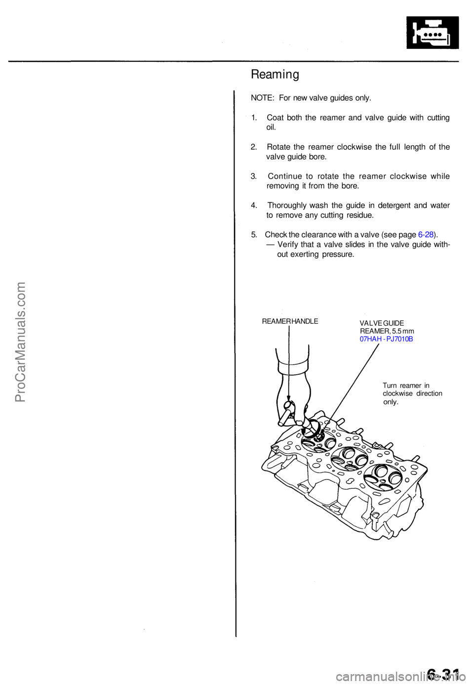
REAMER HANDL E
VALVE GUID E
REAMER , 5. 5 m m
07HA H - PJ7010 B
Tur n reame r i n
clockwis e directio n
only.
ProCarManuals.com
Page 149 of 1771
Water Pum p
Inspectio n
1. Remov e th e timin g bel t (se e pag e 6-6 ).
2 . Tur n th e wate r pum p pulle y counterclockwise .
Check tha t i t turn s freely .
3. Chec k fo r sign s o f sea l leakage .
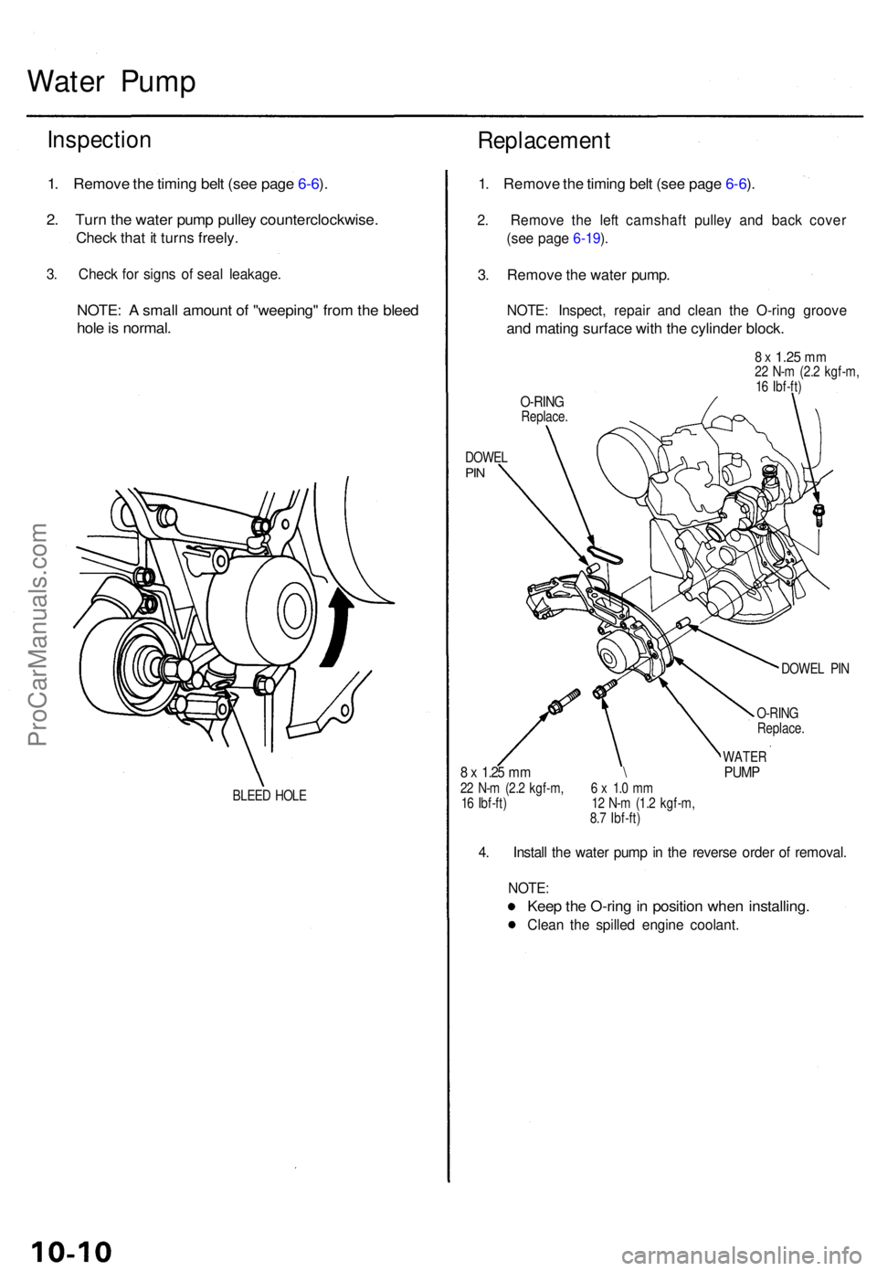
NOTE: A smal l amoun t o f "weeping " fro m th e blee d
hole is normal .
BLEED HOL E
Replacemen t
1. Remov e th e timin g bel t (se e pag e 6-6 ).
2 . Remov e th e lef t camshaf t pulle y an d bac k cove r
(se e pag e 6-19 ).
3 . Remov e th e wate r pump .
NOTE: Inspect , repai r an d clea n th e O-rin g groov e
and matin g surfac e wit h th e cylinde r block .
8 x 1.2 5 mm22 N- m (2. 2 kgf-m ,
1 6 Ibf-ft )
O-RIN GReplace .
DOWE L
PIN
DOWE L PI N
O-RIN G
Replace .
WATER8 x 1.2 5 m m \ PUM P22 N- m (2. 2 kgf-m , 6 x 1. 0 m m
1 6 Ibf-ft ) 1 2 N- m (1. 2 kgf-m ,
8. 7 Ibf-ft )
4. Instal l th e wate r pum p in th e revers e orde r o f removal .
NOTE :
Keep th e O-rin g in positio n whe n installing .
Clean th e spille d engin e coolant .
ProCarManuals.com
Page 486 of 1771
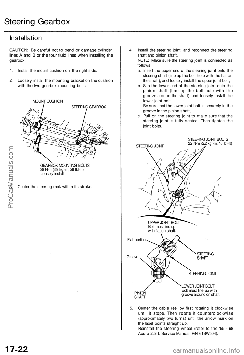
Steering Gearbox
Installation
CAUTION: Be careful not to bend or damage cylinder
lines A and B or the four fluid lines when installing the
gearbox.
1. Install the mount cushion on the right side.
2. Loosely install the mounting bracket on the cushion
with the two gearbox mounting bolts.
MOUNT CUSHION
STEERING GEARBOX
GEARBOX MOUNTING BOLTS
38 N-m (3.9 kgf-m, 28 Ibf-ft)
Loosely install.
3. Center the steering rack within its stroke.
4. Install the steering joint, and reconnect the steering
shaft and pinion shaft.
NOTE: Make sure the steering joint is connected as
follows:
a. Insert the upper end of the steering joint onto the
steering shaft (line up the bolt hole with the flat on
the shaft), and loosely install the upper joint bolt,
b. Slip the lower end of the steering joint onto the
pinion shaft (line up the bolt hole with the
groove around the shaft), and loosely install the
lower joint bolt.
Be sure that the lower joint bolt is securely in the
groove in the pinion shaft,
c. Pull on the steering joint to make sure that the
steering joint is fully seated. Then tighten the
joint bolts.
STEERING JOINT
STEERING JOINT BOLTS
2.2 N-m (2.2 kgf-m, 16 Ibf-ft)
UPPER JOINT BOLT
Bolt must line up
with flat on shaft.
Flat portion.
Groove.
STEERING
SHAFT
PINION
SHAFT
STEERING JOINT
LOWER JOINT BOLT
Bolt must line up with
groove around on shaft.
5. Center the cable reel by first rotating it clockwise
until it stops. Then rotate it counterclockwise
(approximately two turns) until the arrow mark on
the label points straight up.
Reinstall the steering wheel (refer to the '95 - 98
Acura 2.5TL Service Manual, P/N 61SW504):ProCarManuals.com
Page 539 of 1771
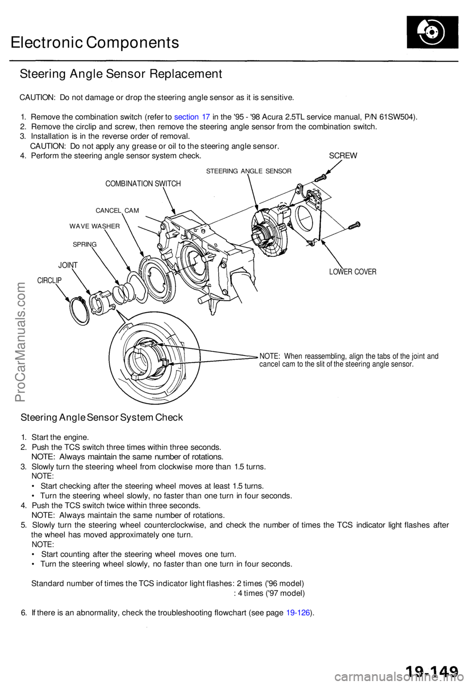
Electronic Component s
Steering Angl e Senso r Replacemen t
CAUTION: D o no t damag e o r dro p th e steerin g angl e senso r a s it i s sensitive .
1 . Remov e th e combinatio n switc h (refe r t o sectio n 1 7 in th e '9 5 - '9 8 Acur a 2.5T L servic e manual , P/ N 61SW504) .
2 . Remov e th e circli p an d screw , the n remov e th e steerin g angl e senso r fro m th e combinatio n switch .
3 . Installatio n i s i n th e revers e orde r o f removal .
CAUTION : D o no t appl y an y greas e o r oi l t o th e steerin g angl e sensor .
4 . Perfor m th e steerin g angl e senso r syste m check . SCRE W
STEERING ANGL E SENSO R
COMBINATIO N SWITC H
CANCE L CA M
WAV E WASHE R
SPRING
LOWER COVE R
NOTE: Whe n reassembling , alig n th e tab s o f th e join t an d
cance l ca m to th e sli t o f th e steerin g angl e sensor .
Steering Angl e Senso r Syste m Chec k
1. Star t th e engine .
2 . Pus h th e TC S switc h thre e time s withi n thre e seconds .
NOTE: Alway s maintai n th e sam e numbe r o f rotations .
3. Slowl y tur n th e steerin g whee l fro m clockwis e mor e tha n 1. 5 turns .
NOTE :
• Star t checkin g afte r th e steerin g whee l move s a t leas t 1. 5 turns .
• Tur n th e steerin g whee l slowly , n o faste r tha n on e tur n in fou r seconds .
4 . Pus h th e TC S switc h twic e withi n thre e seconds .
NOTE : Alway s maintai n th e sam e numbe r o f rotations .
5 . Slowl y tur n th e steerin g whee l counterclockwise , an d chec k th e numbe r o f time s th e TC S indicato r ligh t flashe s afte r
th e whee l ha s move d approximatel y on e turn .
NOTE :
• Star t countin g afte r th e steerin g whee l move s on e turn .
• Tur n th e steerin g whee l slowly , n o faste r tha n on e tur n i n fou r seconds .
Standar d numbe r o f time s th e TC S indicato r ligh t flashes : 2 time s ('9 6 model )
: 4 time s ('9 7 model )
6 . I f ther e is a n abnormality , chec k th e troubleshooting flowchart (se e pag e 19-126 ).
JOIN T
CIRCLI P
ProCarManuals.com
Page 606 of 1771

Alternator Replacemen t
1. Mak e sur e yo u hav e th e anti-thef t cod e fo r th e radio ,
the n writ e dow n th e frequencie s fo r th e radio' s pre -
set buttons .
2. Disconnec t th e batter y negativ e cable , the n discon -
nec t th e positiv e cable .
3 . Remov e th e lowe r mountin g bolt , adjustin g loc k
bol t an d adjustin g rod , the n remov e th e bel t fro m
th e pulley . 4
. A s show n i n th e illustration , rotat e th e alternato r 9 0
degree s counterclockwis e an d pul l i t ou t towar d you .
5 . Disconnec t th e 4 P connecto r an d th e harnes s cli p
bracket , the n remov e th e termina l nu t an d th e BL K
wir e fro m th e B terminal . Tak e ou t th e alternator .
6 . Instal l i n th e revers e orde r o f removal .
7 . Adjus t th e alternato r bel t tensio n (se e pag e 23-89 ).
8 . Ente r th e anti-theft code fo r th e radio , the n ente r th e
customer' s radi o statio n presets .
ProCarManuals.com
Page 615 of 1771
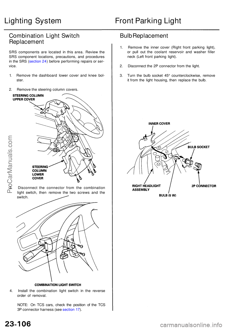
4. Instal l th e combinatio n ligh t switc h i n th e revers e
orde r o f removal .
NOTE : O n TC S cars , chec k th e positio n o f th e TC S
3 P connecto r harnes s (se e sectio n 17 ).
Lightin g Syste m
Combinatio n Ligh t Switc h
Replacemen t
SRS component s ar e locate d i n thi s area . Revie w th e
SR S componen t locations , precautions , an d procedure s
i n th e SR S (sectio n 24 ) befor e performin g repair s o r ser -
vice .
1 . Remov e th e dashboar d lowe r cove r an d kne e bol -
ster .
2 . Remov e th e steerin g colum n covers .
3 . Disconnec t th e connecto r fro m th e combinatio n
ligh t switch , the n remov e th e tw o screw s an d th e
switch .
Front Parkin g Ligh t
Bulb Replacemen t
1. Remov e th e inne r cove r (Righ t fron t parkin g light) ,
o r pul l ou t th e coolan t reservoi r an d washe r fille r
nec k (Lef t fron t parkin g light) .
2 . Disconnec t th e 2 P connecto r fro m th e light .
3 . Tur n th e bul b socke t 45 ° counterclockwise , remov e
i t fro m th e ligh t housing , the n replac e th e bulb .
ProCarManuals.com