1995 ACURA TL clock
[x] Cancel search: clockPage 651 of 1771
Precautions/Procedures
Steering-related Precaution s
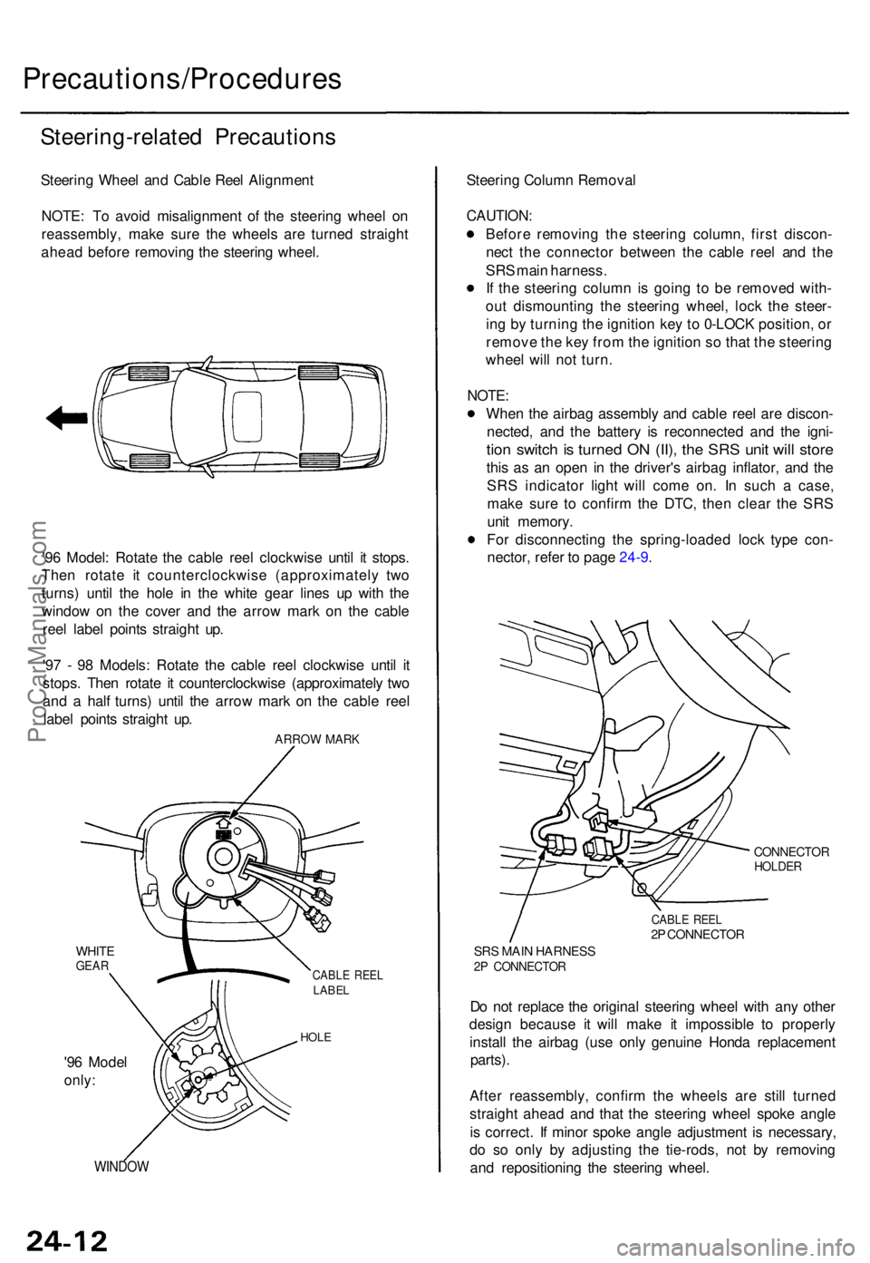
Steering Whee l an d Cabl e Ree l Alignmen t
NOTE : T o avoi d misalignmen t o f th e steerin g whee l o n
reassembly , mak e sur e th e wheel s ar e turne d straigh t
ahea d befor e removin g th e steerin g wheel .
'9 6 Model : Rotat e th e cabl e ree l clockwis e unti l i t stops .
The n rotat e i t counterclockwis e (approximatel y tw o
turns ) unti l th e hol e i n th e whit e gea r line s u p wit h th e
windo w o n th e cove r an d th e arro w mar k o n th e cabl e
ree l labe l point s straigh t up .
'9 7 - 9 8 Models : Rotat e th e cabl e ree l clockwis e unti l i t
stops . The n rotat e i t counterclockwis e (approximatel y tw o
an d a hal f turns ) unti l th e arro w mar k o n th e cabl e ree l
labe l point s straigh t up .
ARRO W MAR K
WHITEGEARCABL E REE LLABE L
HOLE
'96 Mode l
only:
WINDO W
Steering Colum n Remova l
CAUTION :
Before removin g th e steerin g column , firs t discon -
nec t th e connecto r betwee n th e cabl e ree l an d th e
SR S mai n harness .
I f th e steerin g colum n is goin g t o b e remove d with -
ou t dismountin g th e steerin g wheel , loc k th e steer -
in g b y turnin g th e ignitio n ke y t o 0-LOC K position , o r
remov e th e ke y fro m th e ignitio n s o tha t th e steerin g
whee l wil l no t turn .
NOTE :
Whe n th e airba g assembl y an d cabl e ree l ar e discon -
nected , an d th e batter y i s reconnecte d an d th e igni -
tion switc h is turne d O N (II) , th e SR S uni t wil l stor e
this a s a n ope n i n th e driver' s airba g inflator , an d th e
SR S indicato r ligh t wil l com e on . I n suc h a case ,
mak e sur e t o confir m th e DTC , the n clea r th e SR S
uni t memory .
Fo r disconnectin g th e spring-loade d loc k typ e con -
nector , refe r t o pag e 24-9 .
CONNECTO RHOLDER
CABLE REE L2P CONNECTO R
SRS MAI N HARNES S2P CONNECTO R
Do no t replac e th e origina l steerin g whee l wit h an y othe r
desig n becaus e i t will mak e i t impossibl e t o properl y
instal l th e airba g (us e onl y genuin e Hond a replacemen t
parts).
After reassembly , confir m th e wheel s ar e stil l turne d
straigh t ahea d an d tha t th e steerin g whee l spok e angl e
i s correct . I f mino r spok e angl e adjustmen t i s necessary ,
d o s o onl y b y adjustin g th e tie-rods , no t b y removin g
an d repositionin g th e steerin g wheel .
ProCarManuals.com
Page 666 of 1771
Cable Reel
Replacement (cont'd)
12.
NOTE:
Before installing the steering wheel, the front
wheels should be aligned straight ahead.
Be sure to install the harness wires so that they
are not pinched or interfering with other parts.
After reassembly, confirm that the wheels are
still turned straight ahead and that the steering
wheel spoke angle is correct (road test). If minor
spoke angle adjustment is necessary, do so only
by adjusting the tie-rods, not by removing and
repositioning the steering wheel.
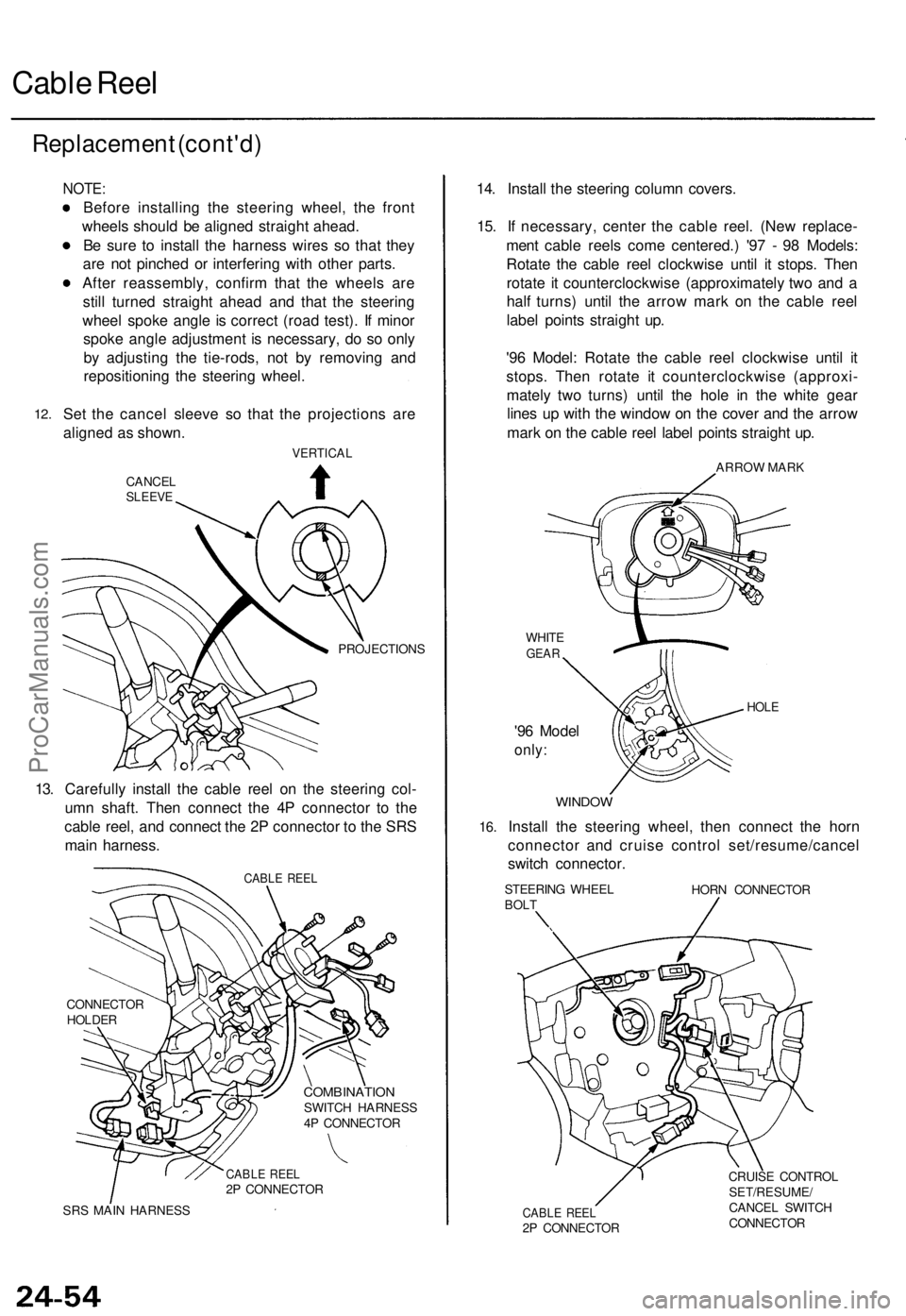
Set the cancel sleeve so that the projections are
aligned as shown.
VERTICAL
CANCEL
SLEEVE
PROJECTIONS
13. Carefully install the cable reel on the steering col-
umn shaft. Then connect the 4P connector to the
cable reel, and connect the 2P connector to the SRS
main harness.
CABLE REEL
CONNECTOR
HOLDER
COMBINATION
SWITCH HARNESS
4P CONNECTOR
CABLE REEL
2P CONNECTOR
SRS MAIN HARNESS
14. Install the steering column covers.
15. If necessary, center the cable reel. (New replace-
ment cable reels come centered.) '97 - 98 Models:
Rotate the cable reel clockwise until it stops. Then
rotate it counterclockwise (approximately two and a
half turns) until the arrow mark on the cable reel
label points straight up.
'96 Model: Rotate the cable reel clockwise until it
stops. Then rotate it counterclockwise (approxi-
mately two turns) until the hole in the white gear
lines up with the window on the cover and the arrow
mark on the cable reel label points straight up.
ARROW MARK
WHITE
GEAR
'96 Model
only:
HOLE
16.
WINDOW
Install the steering wheel, then connect the horn
connector and cruise control set/resume/cancel
switch connector.
STEERING WHEEL
BOLT
HORN CONNECTOR
CABLE REEL
2P CONNECTOR
CRUISE CONTROL
SET/RESUME/
CANCEL SWITCH
CONNECTORProCarManuals.com
Page 738 of 1771
Valve Clearanc e
Adjustmen t (cont'd )
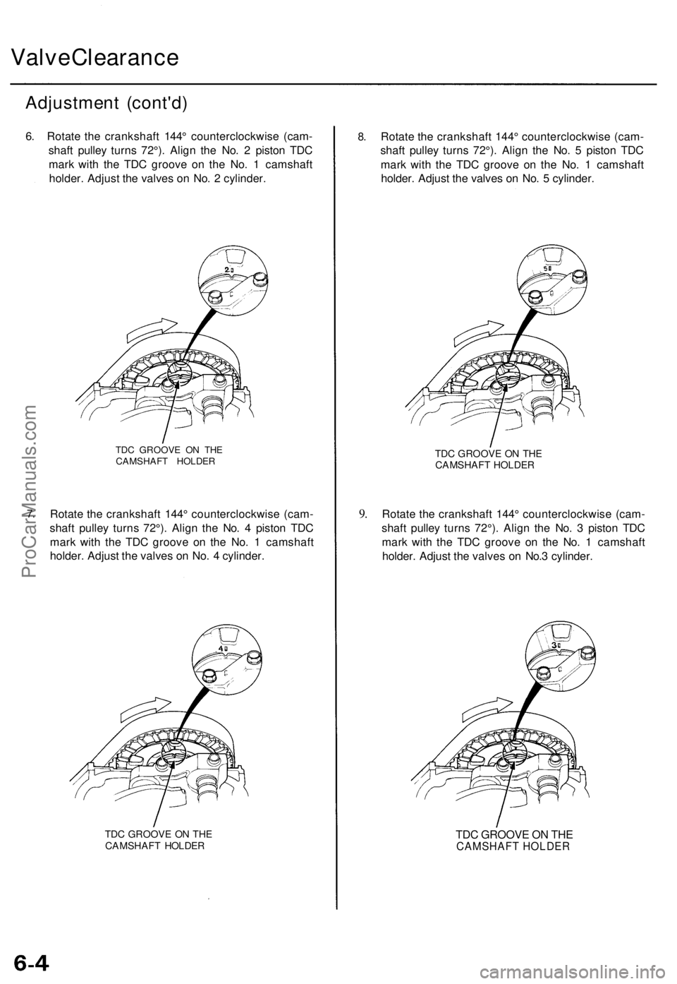
6. Rotat e th e crankshaf t 144 ° counterclockwis e (cam -
shaf t pulle y turn s 72°) . Alig n th e No . 2 pisto n TD C
mar k wit h th e TD C groov e o n th e No . 1 camshaf t
holder . Adjus t th e valve s o n No . 2 cylinder .
7.
TD C GROOV E O N TH ECAMSHAF T HOLDE R
Rotate th e crankshaf t 144 ° counterclockwis e (cam -
shaf t pulle y turn s 72°) . Alig n th e No . 4 pisto n TD C
mar k wit h th e TD C groov e o n th e No . 1 camshaf t
holder . Adjus t th e valve s o n No . 4 cylinder .
TDC GROOV E O N TH ECAMSHAF T HOLDE R
8.Rotat e th e crankshaf t 144 ° counterclockwis e (cam -
shaf t pulle y turn s 72°) . Alig n th e No . 5 pisto n TD C
mar k wit h th e TD C groov e o n th e No . 1 camshaf t
holder . Adjus t th e valve s o n No . 5 cylinder .
9.
TD C GROOV E O N TH ECAMSHAF T HOLDE R
Rotate th e crankshaf t 144 ° counterclockwis e (cam -
shaf t pulle y turn s 72°) . Alig n th e No . 3 pisto n TD C
mar k wit h th e TD C groov e o n th e No . 1 camshaf t
holder . Adjust the valve s o n No. 3 cylinder .
TDC GROOVE ON THE
CAMSHAFT HOLDER
ProCarManuals.com
Page 743 of 1771
Inspection
1. Remov e th e cylinde r hea d cover .
• Refe r t o page s 6-35 , 6-3 6 whe n installing .
2 . Remov e th e uppe r cove r (se e pag e 6-8 ).
3 . Inspec t th e timin g bel t fo r crack s an d oi l o r coolan t
soaking .
NOTE:
• Replac e th e bel t i f oi l o r coolan t soaked .
• Remov e an y oi l o r solven t tha t get s o n th e belt .
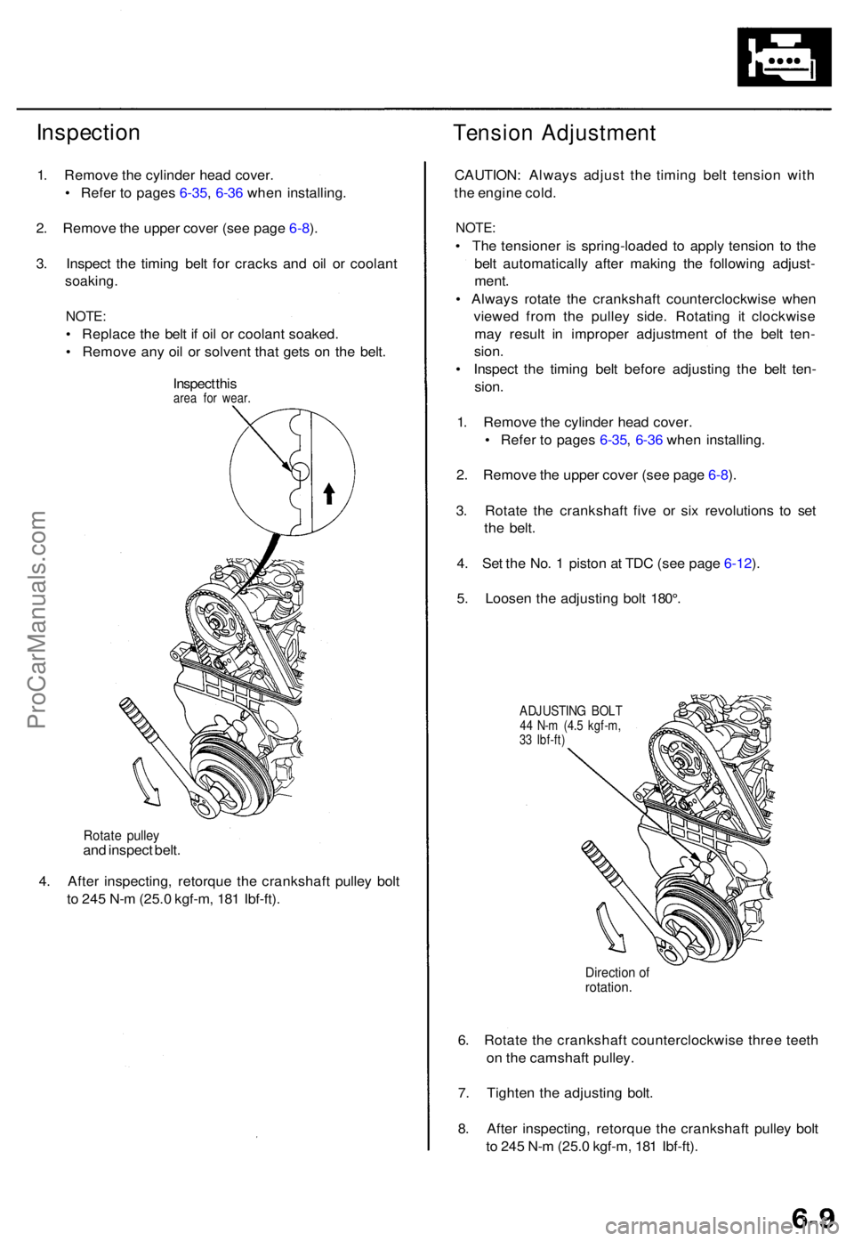
Inspec t thi s
are a fo r wear .
Tensio n Adjustmen t
Rotate pulle yand inspec t belt .
4 . Afte r inspecting , retorqu e th e crankshaf t pulle y bol t
t o 24 5 N- m (25. 0 kgf-m , 18 1 Ibf-ft) . CAUTION
: Alway s adjus t th e timin g bel t tensio n wit h
th e engin e cold .
NOTE :
• Th e tensione r i s spring-loade d t o appl y tensio n t o th e
bel t automaticall y afte r makin g th e followin g adjust -
ment .
• Alway s rotat e th e crankshaf t counterclockwis e whe n
viewe d fro m th e pulle y side . Rotatin g i t clockwis e
ma y resul t i n imprope r adjustmen t of the bel t ten -
sion .
• Inspec t th e timin g bel t befor e adjustin g th e bel t ten -
sion .
1 . Remov e th e cylinde r hea d cover .
• Refe r t o page s 6-35 , 6-3 6 whe n installing .
2 . Remov e th e uppe r cove r (se e pag e 6-8 ).
3 . Rotat e th e crankshaf t fiv e o r si x revolution s t o se t
th e belt .
4 . Se t th e No . 1 pisto n a t TD C (se e pag e 6-12 ).
5 . Loose n th e adjustin g bol t 180° .
ADJUSTIN G BOL T44 N- m (4. 5 kgf-m ,
3 3 Ibf-ft )
Directio n o frotation .
6. Rotat e th e crankshaf t counterclockwis e thre e teet h
o n th e camshaf t pulley .
7 . Tighte n th e adjustin g bolt .
8 . Afte r inspecting , retorqu e th e crankshaf t pulle y bol t
t o 24 5 N- m (25. 0 kgf-m , 18 1 Ibf-ft) .
ProCarManuals.com
Page 746 of 1771
Timing Bel t
Installatio n (cont'd )
6. Instal l th e crankshaf t pulley , the n tighte n th e pulle y
bol t (se e pag e 6-7 ).
7 . Rotat e th e crankshaf t pulle y abou t fiv e o r si x turn s
counterclockwis e s o tha t th e timin g bel t position s o n
th e pulleys .
8 . Adjus t th e timin g bel t tensio n (se e pag e 6-9 ).
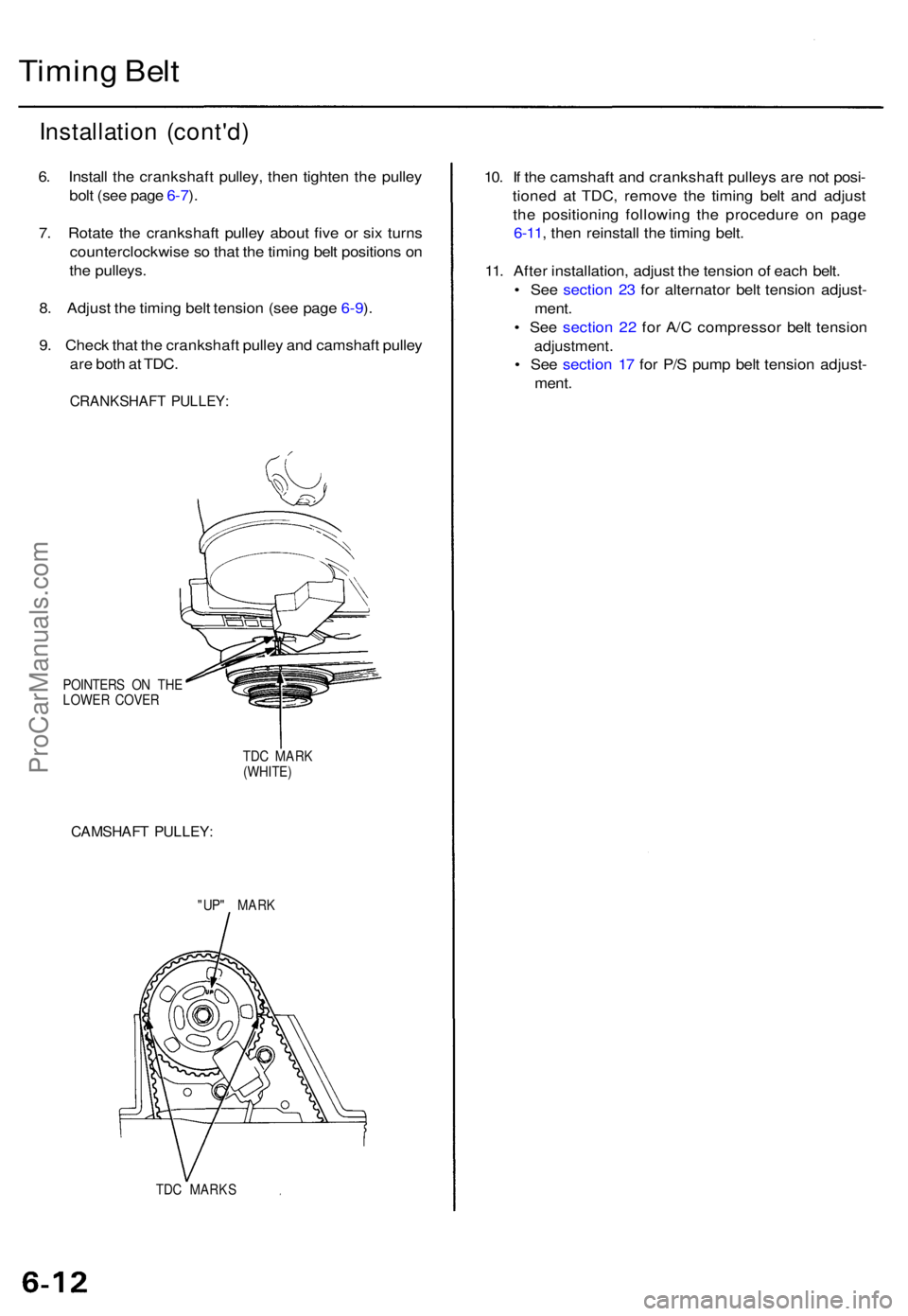
9 . Chec k tha t th e crankshaf t pulle y an d camshaf t pulle y
ar e bot h a t TDC .
CRANKSHAF T PULLEY :
POINTER S O N TH E
LOWE R COVE R
TDC MAR K
(WHITE )
CAMSHAF T PULLEY :
"UP" MAR K
TD C MARK S
10. I f th e camshaf t an d crankshaf t pulley s ar e no t posi -
tione d a t TDC , remov e th e timin g bel t an d adjus t
th e positionin g followin g th e procedur e o n pag e
6-11 , the n reinstal l th e timin g belt .
11 . Afte r installation , adjus t th e tensio n o f eac h belt .
• Se e sectio n 2 3 fo r alternato r bel t tensio n adjust -
ment .
• Se e sectio n 2 2 fo r A/ C compresso r bel t tensio n
adjustment .
• Se e sectio n 1 7 fo r P/ S pum p bel t tensio n adjust -
ment .
ProCarManuals.com
Page 767 of 1771
Valve Guide s
Reamin g
NOTE: Fo r ne w valv e guide s only .
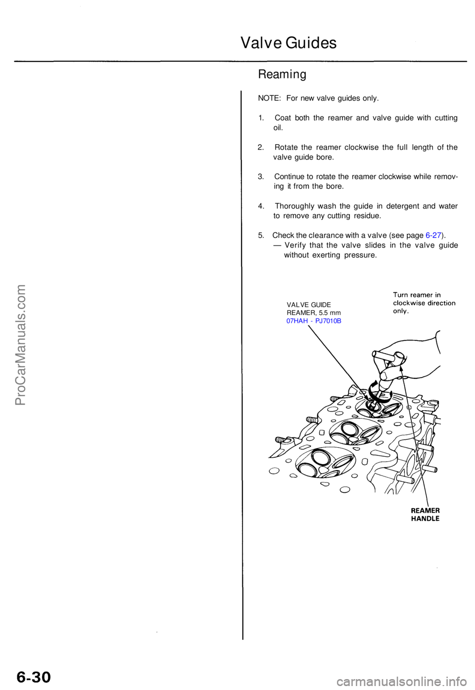
1 . Coa t bot h th e reame r an d valv e guid e wit h cuttin g
oil.
2. Rotat e th e reame r clockwis e th e ful l lengt h o f th e
valv e guid e bore .
3 . Continu e t o rotat e th e reame r clockwis e whil e remov -
in g i t fro m th e bore .
4 . Thoroughl y was h th e guid e i n detergen t an d wate r
t o remov e an y cuttin g residue .
5 . Chec k th e clearanc e wit h a valv e (se e pag e 6-27 ).
— Verif y tha t th e valv e slide s i n th e valv e guid e
withou t exertin g pressure .
VALVE GUID E
REAMER , 5. 5 m m
07HA H - PJ7010 B
ProCarManuals.com
Page 799 of 1771
Crankshaft
Installation
Before installin g th e crankshaft , appl y a coa t
o f engin e oi l t o th e mai n bearing s an d ro d
bearings .
1. Inser t bearin g halve s i n th e cylinde r bloc k an d con -
nectin g rods .
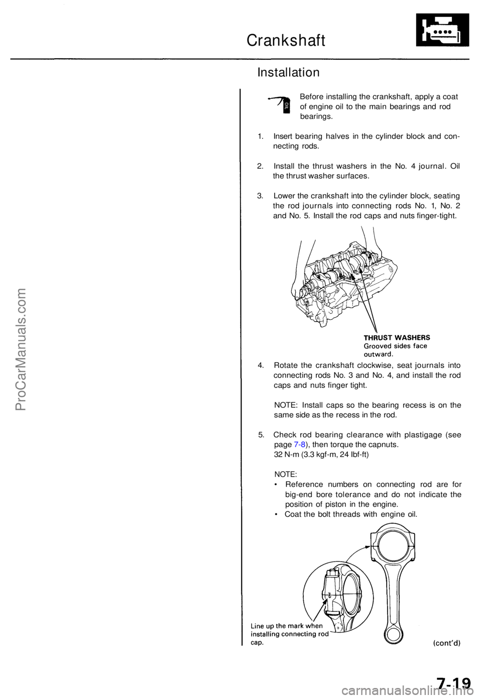
2 . Instal l th e thrus t washer s i n th e No . 4 journal . Oi l
th e thrus t washe r surfaces .
3 . Lowe r th e crankshaf t int o th e cylinde r block , seatin g
th e ro d journal s int o connectin g rod s No . 1 , No . 2
an d No . 5 . Instal l th e ro d cap s an d nut s finger-tight .
4 . Rotat e th e crankshaf t clockwise , sea t journal s int o
connectin g rod s No . 3 an d No . 4 , an d instal l th e ro d
cap s an d nut s finge r tight .
NOTE : Instal l cap s s o th e bearin g reces s i s o n th e
sam e sid e a s th e reces s in th e rod .
5 . Chec k ro d bearin g clearanc e wit h plastigag e (se e
pag e 7-8 ), the n torqu e th e capnuts .
3 2 N- m (3. 3 kgf-m , 2 4 Ibf-ft )
NOTE :
• Referenc e number s o n connectin g ro d ar e fo r
big-en d bor e toleranc e an d d o no t indicat e th e
positio n o f pisto n i n th e engine .
• Coa t th e bol t thread s wit h engin e oil .
ProCarManuals.com
Page 809 of 1771
Oil Filte r
Replacemen t (cont'd )
3. Instal l th e oi l filte r b y hand .
4. Afte r th e rubbe r sea l seats , tighte n th e oi l filte r clock -
wise wit h th e specia l tool .
Tighten : 7/ 8 tur n clockwise .
Tightenin g torque : 2 2 N- m (2. 2 kgf-m , 1 6 Ibf-ft )
OIL FILTE R WRENC H07912-611000 1
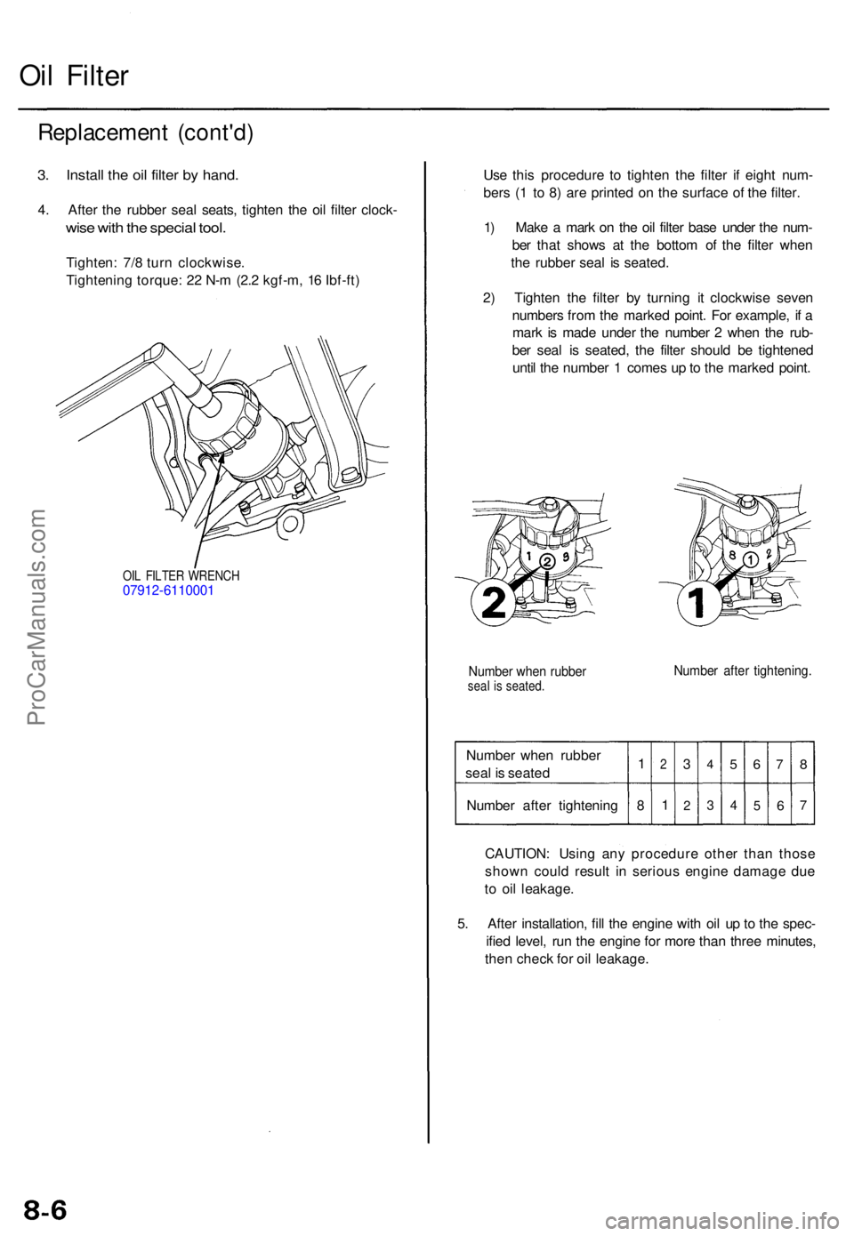
Use thi s procedur e t o tighte n th e filte r i f eigh t num -
ber s ( 1 t o 8 ) ar e printe d o n th e surfac e o f th e filter .
1 ) Mak e a mar k o n th e oi l filte r bas e unde r th e num -
be r tha t show s a t th e botto m o f th e filte r whe n
th e rubber seal i s seated .
2 ) Tighte n th e filte r b y turnin g i t clockwis e seve n
number s fro m th e marke d point . Fo r example , i f a
mar k i s mad e unde r th e numbe r 2 whe n th e rub -
be r sea l i s seated , th e filte r shoul d b e tightene d
unti l th e numbe r 1 come s u p to th e marke d point .
Numbe r whe n rubbe rseal i s seated .Number afte r tightening .
Number whe n rubbe r
sea l i s seate d
Numbe r afte r tightenin g1
8
2
1
3
2
4
3
5
4
6
5
7
6
8
7
CAUTION : Usin g an y procedur e othe r tha n thos e
show n coul d resul t i n seriou s engin e damag e du e
t o oi l leakage .
5 . Afte r installation , fil l th e engin e wit h oi l u p to th e spec -
ifie d level , ru n th e engin e fo r mor e tha n thre e minutes ,
the n chec k fo r oi l leakage .
ProCarManuals.com