Page 830 of 1771
Water Pum p
Inspectio n
1. Remov e th e timin g bel t (se e pag e 6-10 ).
2 . Tur n th e wate r pum p pulle y counterclockwise .
Chec k tha t i t turn s freely .
3 . Chec k fo r sign s o f sea l leakage .
NOTE : A smal l amoun t o f "weeping " fro m th e blee d
hol e is normal .
BLEED HOL E
BLEE D HOL E
Replacemen t
1. Remov e th e timin g bel t (se e pag e 6-10 ).
2 . Remov e th e wate r pum p b y removin g fiv e bolts .
NOTE : Inspect , repai r an d clea n th e O-rin g groov e
an d matin g surfac e wit h th e cylinde r block .
O-RIN GReplace .
WATER PUM P
6 x 1. 0 m m12 N- m (1. 2 kgf-m ,8.7 Ibf-ft )Apply liqui d gaske tto th e bol t threads .
3. Instal l th e wate r pum p in th e revers e orde r o f removal .
NOTE:
• Kee p th e O-rin g i n positio n whe n installing .
• Clea n th e spille d engin e coolant .
ProCarManuals.com
Page 975 of 1771

Troubleshooting Procedures
Checking the Diagnostic Trouble Code (DTC)
with an OBD II Scan tool or Honda PGM Tester
When the TCM senses an abnormality in the input or output systems, the indicator light in the gauge assembly will
blink. When the 16P Data Link Connector (DLC) (located behind the ashtray) is connected to the OBD II Scan Tool or Honda
PGM Tester as shown, the scan tool or tester will indicate the Diagnostic Trouble Code (DTC) when the ignition switch is
turned ON(II).
When the indicator light has been reported on, connect the OBD II Scan Tool conforming to SAE J1978 or Honda PGM
Tester to the DLC (16P) behind the ashtray. Turn the ignition switch on (II), and observe the DTC on the screen of the OBD II
Scan Tool or Honda PGM Tester. After determining the DTC, refer to the electrical system Symptom-to-Component Chart
on page 14-56 and 14-57.
NOTE: See the OBD II Scan Tool or Honda PGM Tester user's manual for specific instruction.
OBD II SCAN TOOL or
HONDA PGM TESTER
Some PGM-FI problems will also make the indicator light come on. After repairing the PGM-FI system, disconnect the
BACK UP RADIO fuse (10 A) in the under-hood fuse/relay box for more than 10 seconds to reset the TCM memory, then
retest.
NOTE: Disconnecting the BACK UP RADIO fuse also cancels the radio anti-theft code, preset stations and the clock setting.
Get the customer's code number, and make note of the radio presets before removing the fuse so you can reset them.
DATA LINK CONNECTOR (16P)ProCarManuals.com
Page 1172 of 1771

Installation
Airbag installation
CAUTION:
• Before installing the steering wheel, align the front
wheels straight ahead.
• Be sure to install the harness wires so that they are
not pinched or interfering with other vehicle parts.
• Do not replace the original steering wheel with any
other design, since it will make it impossible to prop-
erly install the airbag. (Only use genuine Honda
replacement parts)
• After reassembly, confirm that the wheels are still
straight ahead and that steering wheel spoke angle
is correct. If minor spoke angle adjustment is neces-
sary, do so only by adjustment of the tie-rods, not by
removing and repositioning the steering wheel.
Confirm that the airbag assembly is
securely attached to the steering wheel; otherwise,
severe personal injury could result during airbag
deployment.
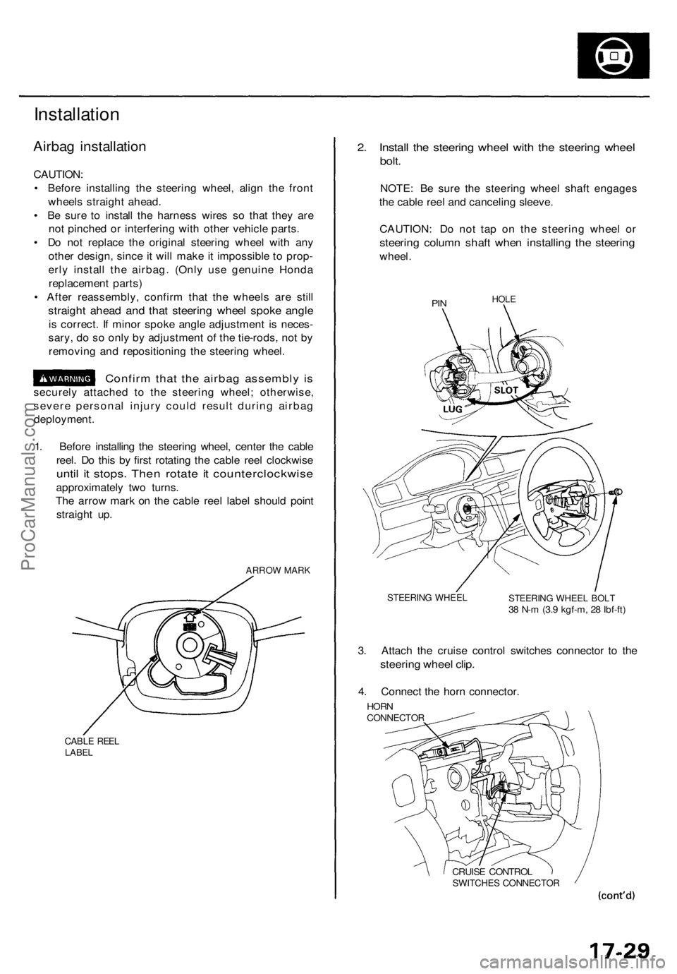
1. Before installing the steering wheel, center the cable
reel. Do this by first rotating the cable reel clockwise
until it stops. Then rotate it counterclockwise
approximately two turns.
The arrow mark on the cable reel label should point
straight up.
ARROW MARK
CABLE REEL
LABEL
2. Install the steering wheel with the steering wheel
bolt.
NOTE: Be sure the steering wheel shaft engages
the cable reel and canceling sleeve.
CAUTION: Do not tap on the steering wheel or
steering column shaft when installing the steering
wheel.
PIN
HOLE
STEERING WHEEL
STEERING WHEEL BOLT
38 N-m (3.9 kgf-m, 28 Ibf-ft)
3. Attach the cruise control switches connector to the
steering wheel clip.
4. Connect the horn connector.
HORN
CONNECTOR
CRUISE CONTROL
SWITCHES CONNECTORProCarManuals.com
Page 1212 of 1771

4. Instal l th e steerin g joint , an d reconnec t th e steerin g
shaf t an d pinio n shaft .
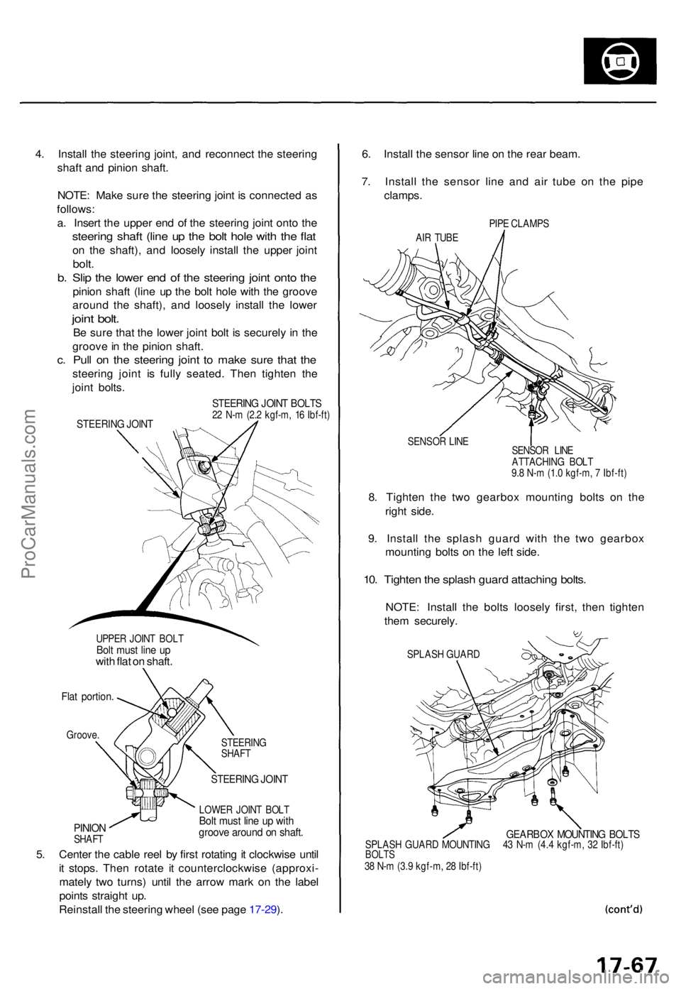
NOTE : Mak e sur e th e steerin g join t i s connecte d a s
follows :
a . Inser t th e uppe r en d o f th e steerin g join t ont o th e
steerin g shaf t (lin e u p th e bol t hol e wit h th e fla t
on th e shaft) , an d loosel y instal l th e uppe r join t
bolt.
b. Sli p th e lowe r en d o f th e steerin g join t ont o th e
pinio n shaf t (lin e u p th e bol t hol e wit h th e groov e
aroun d th e shaft) , an d loosel y instal l th e lowe r
joint bolt .
Be sur e tha t th e lowe r join t bol t i s securel y i n th e
groov e in th e pinio n shaft .
c. Pul l o n th e steerin g join t t o mak e sur e tha t th e
steerin g join t i s full y seated . The n tighte n th e
join t bolts .
UPPE R JOIN T BOL TBolt mus t lin e u pwit h fla t o n shaft .
Flat portion .
Groove.
PINIONSHAF T STEERIN
G
SHAF T
STEERIN G JOIN T
LOWE R JOIN T BOL TBolt mus t lin e u p wit hgroov e aroun d o n shaft .
5. Cente r th e cabl e ree l b y firs t rotatin g it clockwis e unti l
i t stops . The n rotat e i t counterclockwis e (approxi -
matel y tw o turns ) unti l th e arro w mar k o n th e labe l
point s straigh t up .
Reinstal l th e steerin g whee l (se e pag e 17-29 ). 6
. Instal l th e senso r lin e o n th e rea r beam .
7 . Instal l th e senso r lin e an d ai r tub e o n th e pip e
clamps .
PIPE CLAMP S
AI R TUB E
SENSO R LIN E
8. Tighte n th e tw o gearbo x mountin g bolt s o n th e
righ t side .
9 . Instal l th e splas h guar d wit h th e tw o gearbo x
mountin g bolt s o n th e lef t side .
10. Tighte n th e splas h guar d attachin g bolts .
NOTE : Instal l th e bolt s loosel y first , the n tighte n
the m securely .
SPLASH GUAR D
GEARBO X MOUNTIN G BOLT SSPLAS H GUAR D MOUNTIN G 4 3 N- m (4. 4 kgf-m , 3 2 Ibf-ft )BOLT S38 N- m (3. 9 kgf-m , 2 8 Ibf-ft )
STEERIN G JOIN T BOLT S22 N- m (2. 2 kgf-m , 1 6 Ibf-ft )STEERIN G JOIN T
SENSO R LIN E
ATTACHIN G BOL T
9. 8 N- m (1. 0 kgf-m , 7 Ibf-ft )
ProCarManuals.com
Page 1268 of 1771

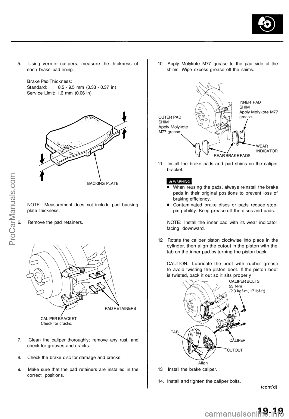
5. Using vernier calipers, measure the thickness of
each brake pad lining.
Brake Pad Thickness:
Standard: 8.5 - 9.5 mm (0.33 - 0.37 in)
Service Limit: 1.6 mm (0.06 in)
BACKING PLATE
NOTE: Measurement does not include pad backing
plate thickness.
6. Remove the pad retainers.
PAD RETAINERS
CALIPER BRACKET
Check for cracks.
7. Clean the caliper thoroughly; remove any rust, and
check for grooves and cracks.
8. Check the brake disc for damage and cracks.
9. Make sure that the pad retainers are installed in the
correct positions.
10. Apply Molykote M77 grease to the pad side of the
shims. Wipe excess grease off the shims.
OUTER PAD
SHIM
Apply Molykote
M77 grease.
INNER PAD
SHIM
Apply Molykote M77
grease.
WEAR
INDICATOR
REAR BRAKE PADS
11. Install the brake pads and pad shims on the caliper
bracket.
When reusing the pads, always reinstall the brake
pads in their original positions to prevent loss of
braking efficiency.
Contaminated brake discs or pads reduce stop-
ping ability. Keep grease off the discs and pads.
NOTE: Install the inner pad with its wear indicator
facing downward.
12. Rotate the caliper piston clockwise into place in the
cylinder, then align the cutout in the piston with the
tab on the inner pad by turning the piston back.
CAUTION: Lubricate the boot with rubber grease
to avoid twisting the piston boot. If the piston boot
is twisted, back it out so it sits properly.
CALIPER BOLTS
23 N-m
(2.3 kgf-m, 17 Ibf-ft)
TAB
CUTOUT
Align
13. Install the brake caliper.
14. Install and tighten the caliper bolts.
CALIPERProCarManuals.com
Page 1273 of 1771
Rear Brake Caliper
Disassembly (cont'd)
3. Remove the banjo bolt and two sealing washers.
CALIPER BRACKET
Check for cracks.
CALIPER BOLTS
SEALING
WASHERS
Replace.
BANJO
BOLT
4. Remove the two caliper bolts and caliper body from
the bracket.
5. Remove the pins and pin boots from the caliper
bracket.
PIN B
PIN A
PIN BOOTS
Replace.
6. Remove the pad spring from the caliper body.
PAD SPRING
7. Remove the piston by rotating the piston counter-
clockwise with the tool, and remove the piston
boot.
CAUTION: Avoid damaging the piston.
PISTON BOOT
Replace.
LOCKNUT WRENCH
(Commercially
available)
PISTON
Check for scoring.ProCarManuals.com
Page 1274 of 1771

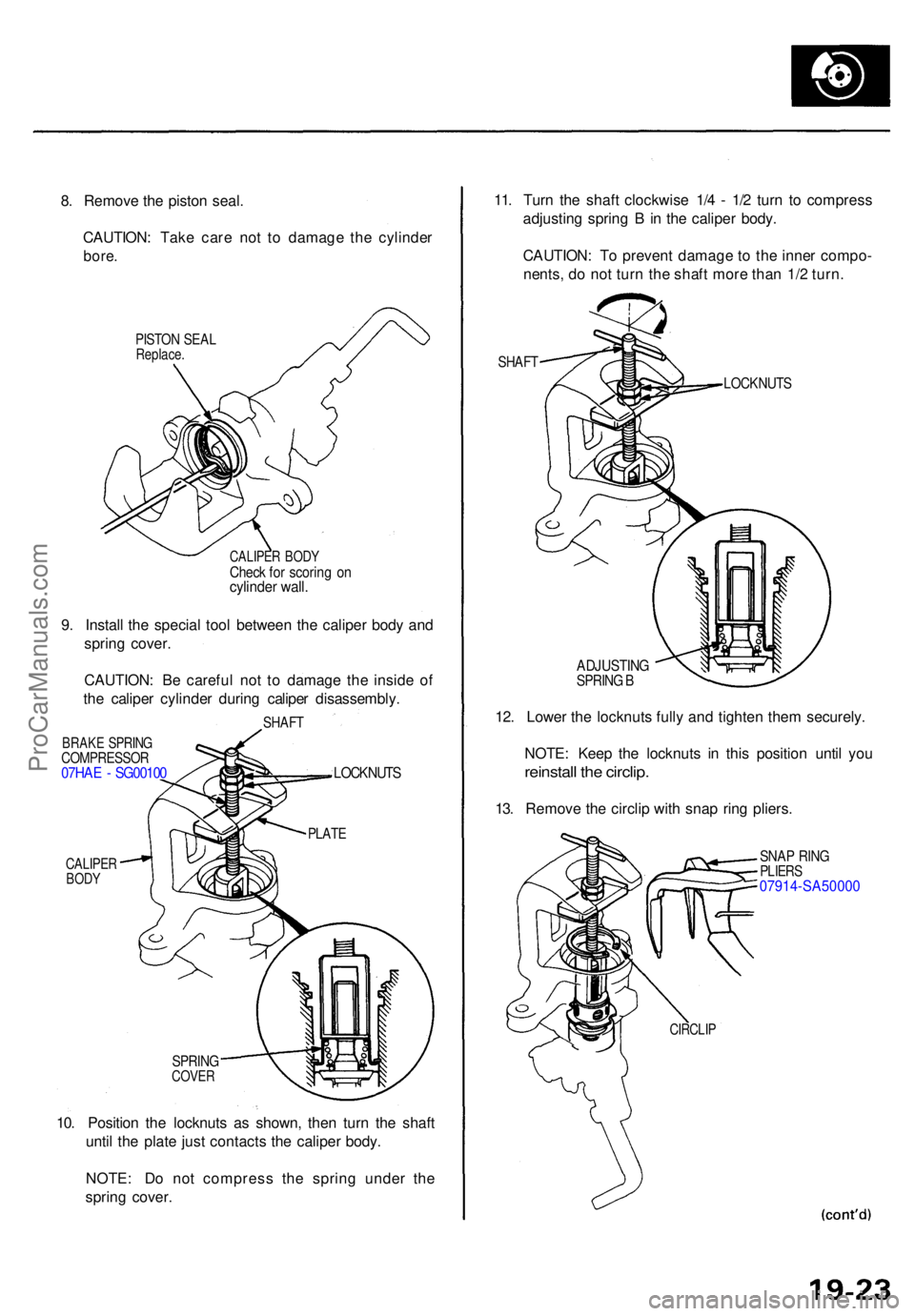
8. Remov e th e pisto n seal .
CAUTION : Tak e car e no t t o damag e th e cylinde r
bore.
PISTO N SEA LReplace .
CALIPER BOD YCheck fo r scorin g o ncylinde r wall .
9. Instal l th e specia l too l betwee n th e calipe r bod y an d
sprin g cover .
CAUTION : B e carefu l no t t o damag e th e insid e o f
th e calipe r cylinde r durin g calipe r disassembly .
SHAFT
BRAK E SPRIN GCOMPRESSO R07HAE - SG0010 0
CALIPERBODY
LOCKNUT S
SPRINGCOVER
10. Positio n th e locknut s a s shown , the n tur n th e shaf t
unti l th e plat e jus t contact s th e calipe r body .
NOTE : D o no t compres s th e sprin g unde r th e
sprin g cover . 11
. Tur n th e shaf t clockwis e 1/ 4 - 1/ 2 tur n t o compres s
adjustin g sprin g B in th e calipe r body .
CAUTION : T o preven t damag e t o th e inne r compo -
nents , d o no t tur n th e shaf t mor e tha n 1/ 2 turn .
SHAF T
LOCKNUT S
ADJUSTIN GSPRING B
12 . Lowe r th e locknut s full y an d tighte n the m securely .
NOTE : Kee p th e locknut s i n thi s positio n unti l yo u
reinstal l th e circlip .
13. Remov e th e circli p wit h sna p rin g pliers .
SNAP RIN GPLIER S07914-SA5000 0
CIRCLIP
PLATE
ProCarManuals.com
Page 1275 of 1771
Rear Brake Caliper
Disassembly (cont'd)
14. Hold the plate with your fingers, and turn the shaft
counterclockwise. Remove the special tool from the
caliper.
LOCKNUTS
PLATE
15. Remove the adjusting bolt.
ADJUSTING SPRING B
Check for weakness.
SPACER
SPRING COVER
Check for damage.
CUP
Replace.
ADJUSTING BOLT
Check for wear and
damage.
16. Remove the spring cover, adjusting spring B, spacer,
bearing A and cup from the adjusting bolt.
17. Remove the sleeve piston, and remove the pin from
the cam in the caliper body.
O-RING
Replace.
PIN
SLEEVE PISTON
Check for wear and
damage.
18. Remove the return spring.
RETURN
SPRING
PARKING LEVER/
CAM ASSEMBLY
Check for damage
CAM BOOT
Replace.
19. Remove the parking lever and cam as an assembly
from the caliper body.
CAUTION: Do not loosen the parking nut with the
cam installed in the caliper body. K the lever and shaft
must be separated, hold the lever in a vise and loosen
the parking nut.
20. Remove the cam boot.ProCarManuals.com