Page 1668 of 1771
Replacement
1. Remov e th e instrumen t panel , (se e sectio n 20 )
2 . Remov e th e cloc k fro m th e instrumen t panel .
CLOCK
Terminal s
INSTRUMEN T PANE L
3. Instal l i n th e revers e orde r o f removal .
TERMINA L SID E O F MAL E TERMINAL S
ProCarManuals.com
Page 1717 of 1771

Cruise Control
Description (cont'd)
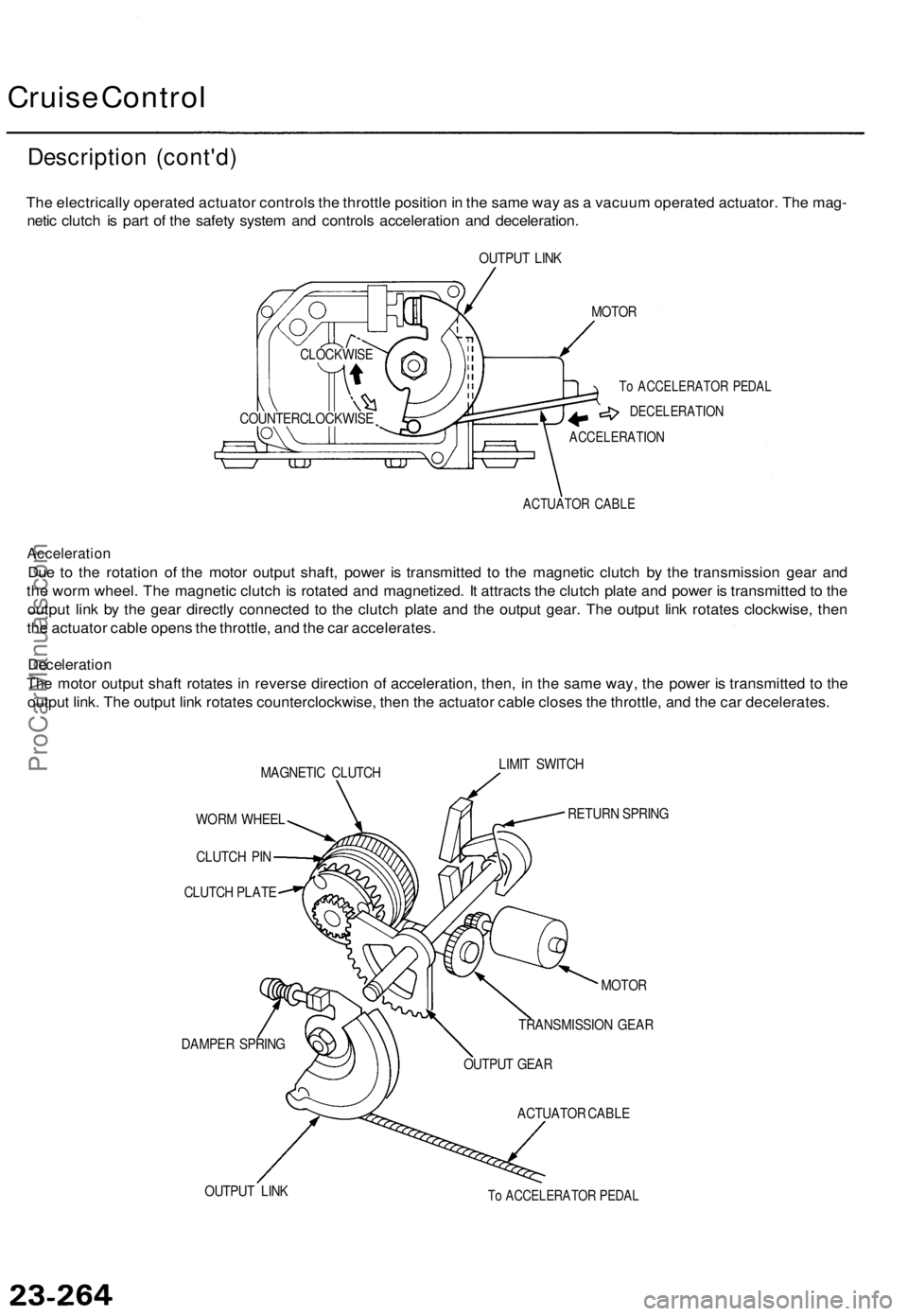
The electrically operated actuator controls the throttle position in the same way as a vacuum operated actuator. The mag-
netic clutch is part of the safety system and controls acceleration and deceleration.
OUTPUT LINK
MOTOR
To ACCELERATOR PEDAL
DECELERATION
ACCELERATION
ACTUATOR CABLE
Acceleration
Due to the rotation of the motor output shaft, power is transmitted to the magnetic clutch by the transmission gear and
the worm wheel. The magnetic clutch is rotated and magnetized. It attracts the clutch plate and power is transmitted to the
output link by the gear directly connected to the clutch plate and the output gear. The output link rotates clockwise, then
the actuator cable opens the throttle, and the car accelerates.
Deceleration
The motor output shaft rotates in reverse direction of acceleration, then, in the same way, the power is transmitted to the
output link. The output link rotates counterclockwise, then the actuator cable closes the throttle, and the car decelerates.
MAGNETIC CLUTCH
LIMIT SWITCH
WORM WHEEL
CLUTCH PIN
CLUTCH PLATE
DAMPER SPRING
RETURN SPRING
OUTPUT LINK
MOTOR
TRANSMISSION GEAR
OUTPUT GEAR
ACTUATOR CABLE
To ACCELERATOR PEDAL
COUNTERCLOCKWISE
CLOCKWISEProCarManuals.com
Page 1746 of 1771

Steering-related Precautions
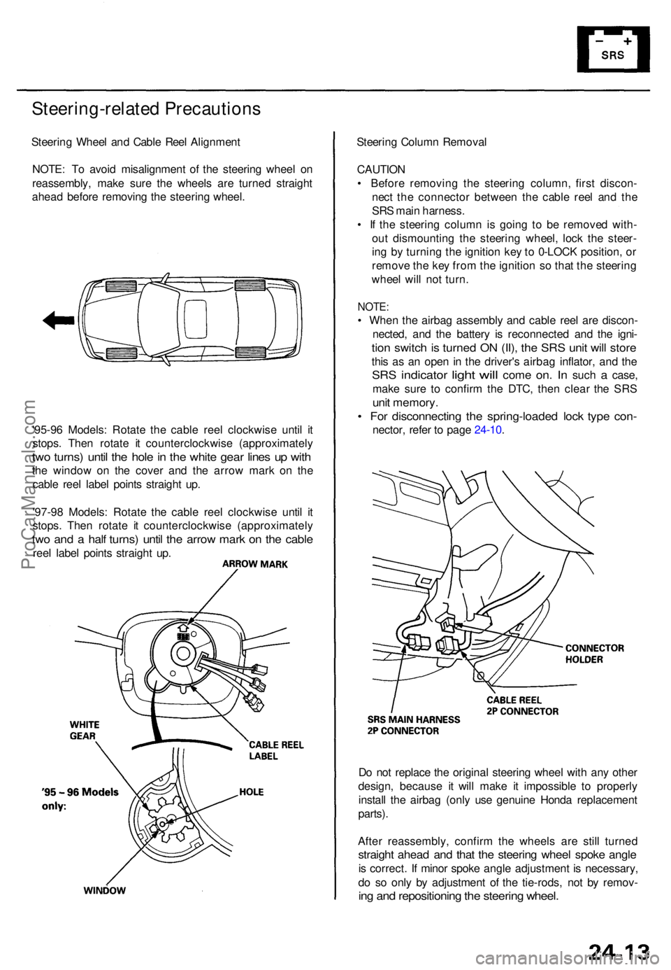
Steering Whee l an d Cabl e Ree l Alignmen t
NOTE : T o avoi d misalignmen t o f th e steerin g whee l o n
reassembly , mak e sur e th e wheel s ar e turne d straigh t
ahea d befor e removin g th e steerin g wheel .
'95-9 6 Models : Rotat e th e cabl e ree l clockwis e unti l i t
stops . The n rotat e i t counterclockwis e (approximatel y
two turns ) unti l th e hol e in th e whit e gea r line s u p wit h
the windo w o n th e cove r an d th e arro w mar k o n th e
cabl e ree l labe l point s straigh t up .
'97-9 8 Models : Rotat e th e cabl e ree l clockwis e unti l i t
stops . The n rotat e i t counterclockwis e (approximatel y
two an d a hal f turns ) unti l th e arro w mar k o n th e cabl e
reel labe l point s straigh t up . Steerin
g Colum n Remova l
CAUTIO N
• Befor e removin g th e steerin g column , firs t discon -
nec t th e connecto r betwee n th e cabl e ree l an d th e
SR S mai n harness .
• I f th e steerin g colum n i s goin g t o b e remove d with -
ou t dismountin g th e steerin g wheel , loc k th e steer -
in g b y turnin g th e ignitio n ke y to 0-LOC K position , o r
remov e th e ke y fro m th e ignitio n s o tha t th e steerin g
whee l wil l no t turn .
NOTE :
• Whe n th e airba g assembl y an d cabl e ree l ar e discon -
nected , an d th e batter y i s reconnecte d an d th e igni -
tion switc h is turne d O N (II) , th e SR S uni t wil l stor e
this a s a n ope n i n th e driver' s airba g inflator , an d th e
SR S indicato r light will com e on. I n suc h a case ,
mak e sur e t o confir m th e DTC , the n clea r th e SR S
unit memory .
• Fo r disconnectin g th e spring-loade d loc k typ e con -
nector , refe r t o pag e 24-10 .
D o no t replac e th e origina l steerin g whee l wit h an y othe r
design , becaus e i t wil l mak e i t impossibl e t o properly
instal l th e airba g (onl y us e genuin e Hond a replacemen t
parts) .
Afte r reassembly , confir m th e wheel s ar e stil l turne d
straight ahea d an d tha t th e steerin g whee l spok e angl e
is correct . I f mino r spok e angl e adjustment is necessary ,
d o s o onl y b y adjustmen t o f th e tie-rods , no t b y remov -
ing an d repositionin g th e steerin g wheel .
ProCarManuals.com
Page 1767 of 1771

NOTE:
• Befor e installin g th e steerin g wheel , th e fron t
wheel s shoul d b e aligne d straigh t ahead .
• B e sur e t o instal l th e harnes s wire s s o tha t the y
are no t pinche d o r interferin g wit h othe r parts .
• Afte r reassembly , confir m tha t th e wheel s ar e
stil l turne d straigh t ahea d an d tha t th e steerin g
whee l spok e angl e i s correc t (roa d test) . I f mino r
spok e angl e adjustmen t i s necessary , d o s o onl y
b y adjustin g th e tie-rods , no t b y removin g an d
repositionin g th e steerin g wheel .
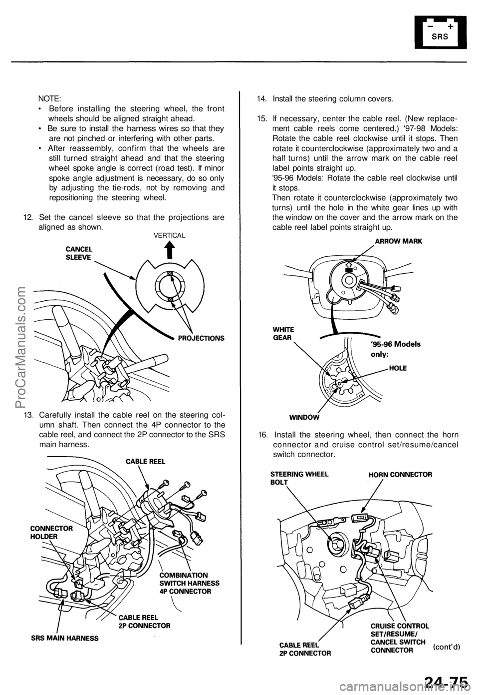
12 . Se t th e cance l sleev e s o tha t th e projection s ar e
aligne d a s shown .
VERTICA L
14. Instal l th e steerin g colum n covers .
15 . I f necessary , cente r th e cabl e reel . (Ne w replace -
men t cabl e reel s com e centered. ) '97-9 8 Models :
Rotat e th e cabl e ree l clockwis e unti l i t stops . The n
rotat e it counterclockwis e (approximatel y tw o an d a
hal f turns ) unti l th e arro w mar k o n th e cabl e ree l
labe l point s straigh t up .
'95-9 6 Models : Rotat e th e cabl e ree l clockwis e unti l
i t stops .
The n rotat e i t counterclockwis e (approximatel y tw o
turns ) unti l th e hol e i n th e whit e gea r line s u p wit h
th e windo w o n th e cove r an d th e arro w mar k o n th e
cabl e ree l labe l point s straigh t up .
16 . Instal l th e steerin g wheel , the n connec t th e hor n
connecto r an d cruis e contro l set/resume/cance l
switc h connector .
13
. Carefull y instal l th e cabl e ree l o n th e steerin g col -
um n shaft . The n connec t th e 4 P connecto r t o th e
cabl e reel , an d connec t th e 2 P connecto r t o th e SR S
mai n harness .
ProCarManuals.com