1994 JEEP CHEROKEE clock
[x] Cancel search: clockPage 1347 of 1784
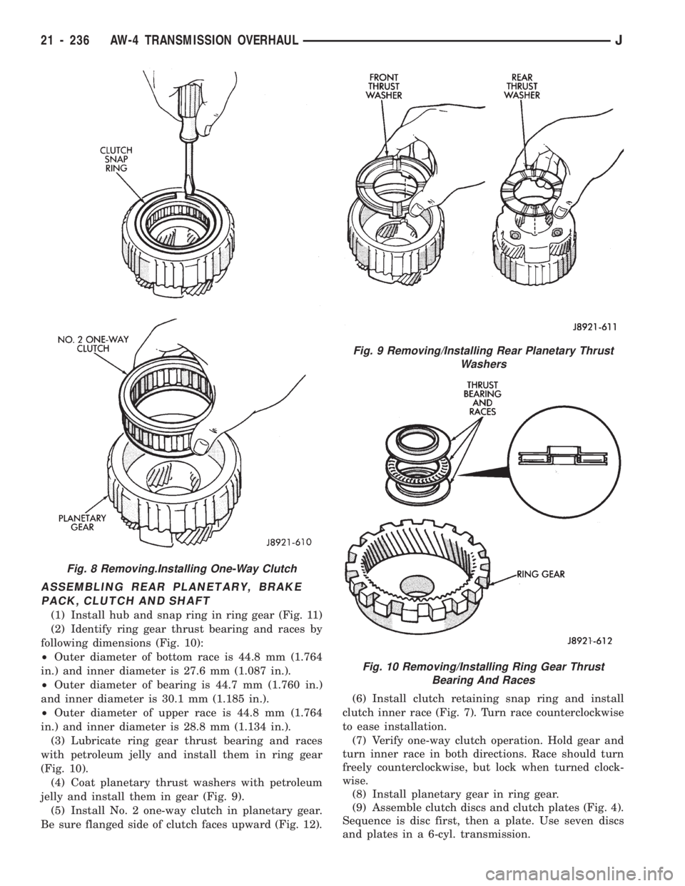
ASSEMBLING REAR PLANETARY, BRAKE
PACK, CLUTCH AND SHAFT
(1) Install hub and snap ring in ring gear (Fig. 11)
(2) Identify ring gear thrust bearing and races by
following dimensions (Fig. 10):
²Outer diameter of bottom race is 44.8 mm (1.764
in.) and inner diameter is 27.6 mm (1.087 in.).
²Outer diameter of bearing is 44.7 mm (1.760 in.)
and inner diameter is 30.1 mm (1.185 in.).
²Outer diameter of upper race is 44.8 mm (1.764
in.) and inner diameter is 28.8 mm (1.134 in.).
(3) Lubricate ring gear thrust bearing and races
with petroleum jelly and install them in ring gear
(Fig. 10).
(4) Coat planetary thrust washers with petroleum
jelly and install them in gear (Fig. 9).
(5) Install No. 2 one-way clutch in planetary gear.
Be sure flanged side of clutch faces upward (Fig. 12).(6) Install clutch retaining snap ring and install
clutch inner race (Fig. 7). Turn race counterclockwise
to ease installation.
(7) Verify one-way clutch operation. Hold gear and
turn inner race in both directions. Race should turn
freely counterclockwise, but lock when turned clock-
wise.
(8) Install planetary gear in ring gear.
(9) Assemble clutch discs and clutch plates (Fig. 4).
Sequence is disc first, then a plate. Use seven discs
and plates in a 6-cyl. transmission.
Fig. 8 Removing.Installing One-Way Clutch
Fig. 9 Removing/Installing Rear Planetary Thrust
Washers
Fig. 10 Removing/Installing Ring Gear Thrust
Bearing And Races
21 - 236 AW-4 TRANSMISSION OVERHAULJ
Page 1388 of 1784
(11) Adjust transfer case shift linkage.
(12) Lower vehicle.
TRANSFER CASE DISASSEMBLY AND OVERHAUL
Two versions of the NP231 are used in current
models. One version retains the synchronizer
components used in previous years. A newly intro-
duced version does not have synchro components.
The non-synchro version does not have a synchro
gear, struts, spring and stop ring. During over-
haul, note which version is being serviced and or-
der needed parts accordingly.
(1) Remove fill and drain plugs.
(2) Remove front yoke. Discard yoke seal washer
and nut. They should not be reused.
(3) Move transfer case range lever rearward to 4L
position.
(4) Remove extension housing attaching bolts.
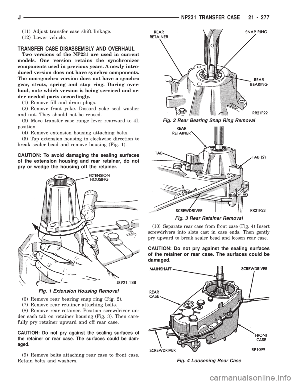
(5) Tap extension housing in clockwise direction to
break sealer bead and remove housing (Fig. 1).
CAUTION: To avoid damaging the sealing surfaces
of the extension housing and rear retainer, do not
pry or wedge the housing off the retainer.
(6) Remove rear bearing snap ring (Fig. 2).
(7) Remove rear retainer attaching bolts.
(8) Remove rear retainer. Position screwdriver un-
der each tab on retainer housing (Fig. 3). Then care-
fully pry retainer upward and off rear case.
CAUTION: Do not pry against the sealing surfaces of
the retainer or rear case. The surfaces could be dam-
aged.
(9) Remove bolts attaching rear case to front case.
Retain bolts and washers.
(10) Separate rear case from front case (Fig. 4) Insert
screwdrivers into slots cast in case ends. Then gently
pry upward to break sealer bead and loosen rear case.
CAUTION: Do not pry against the sealing surfaces
of the retainer or rear case. The surfaces could be
damaged.
Fig. 1 Extension Housing Removal
Fig. 2 Rear Bearing Snap Ring Removal
Fig. 3 Rear Retainer Removal
Fig. 4 Loosening Rear Case
JNP231 TRANSFER CASE 21 - 277
Page 1408 of 1784
TRANSFER CASE DISASSEMBLY AND OVERHAUL
(1) Remove fill and drain plugs.
(2) Remove front yoke. Discard yoke seal washer
and nut.
(3) Move range lever rearward to 4L position.
(4) Remove extension housing attaching bolts.
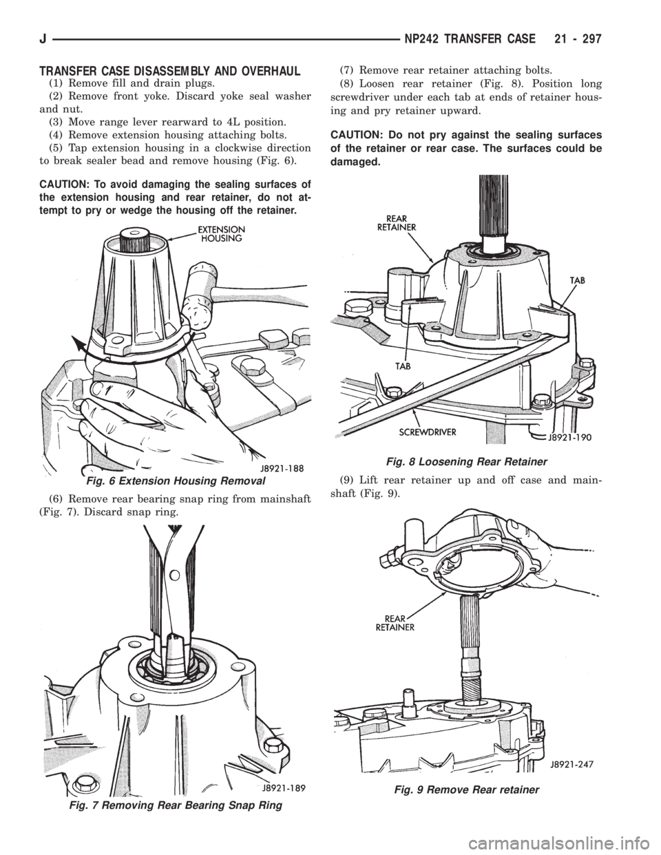
(5) Tap extension housing in a clockwise direction
to break sealer bead and remove housing (Fig. 6).
CAUTION: To avoid damaging the sealing surfaces of
the extension housing and rear retainer, do not at-
tempt to pry or wedge the housing off the retainer.
(6) Remove rear bearing snap ring from mainshaft
(Fig. 7). Discard snap ring.(7) Remove rear retainer attaching bolts.
(8) Loosen rear retainer (Fig. 8). Position long
screwdriver under each tab at ends of retainer hous-
ing and pry retainer upward.
CAUTION: Do not pry against the sealing surfaces
of the retainer or rear case. The surfaces could be
damaged.
(9) Lift rear retainer up and off case and main-
shaft (Fig. 9).
Fig. 7 Removing Rear Bearing Snap Ring
Fig. 6 Extension Housing Removal
Fig. 8 Loosening Rear Retainer
Fig. 9 Remove Rear retainer
JNP242 TRANSFER CASE 21 - 297
Page 1411 of 1784
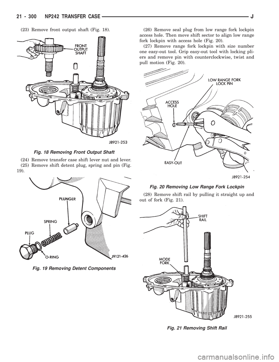
(23) Remove front output shaft (Fig. 18).
(24) Remove transfer case shift lever nut and lever.
(25) Remove shift detent plug, spring and pin (Fig.
19).(26) Remove seal plug from low range fork lockpin
access hole. Then move shift sector to align low range
fork lockpin with access hole (Fig. 20).
(27) Remove range fork lockpin with size number
one easy-out tool. Grip easy-out tool with locking pli-
ers and remove pin with counterclockwise, twist and
pull motion (Fig. 20).
(28) Remove shift rail by pulling it straight up and
out of fork (Fig. 21).
Fig. 18 Removing Front Output Shaft
Fig. 19 Removing Detent Components
Fig. 20 Removing Low Range Fork Lockpin
Fig. 21 Removing Shift Rail
21 - 300 NP242 TRANSFER CASEJ
Page 1526 of 1784
INSTALLATION
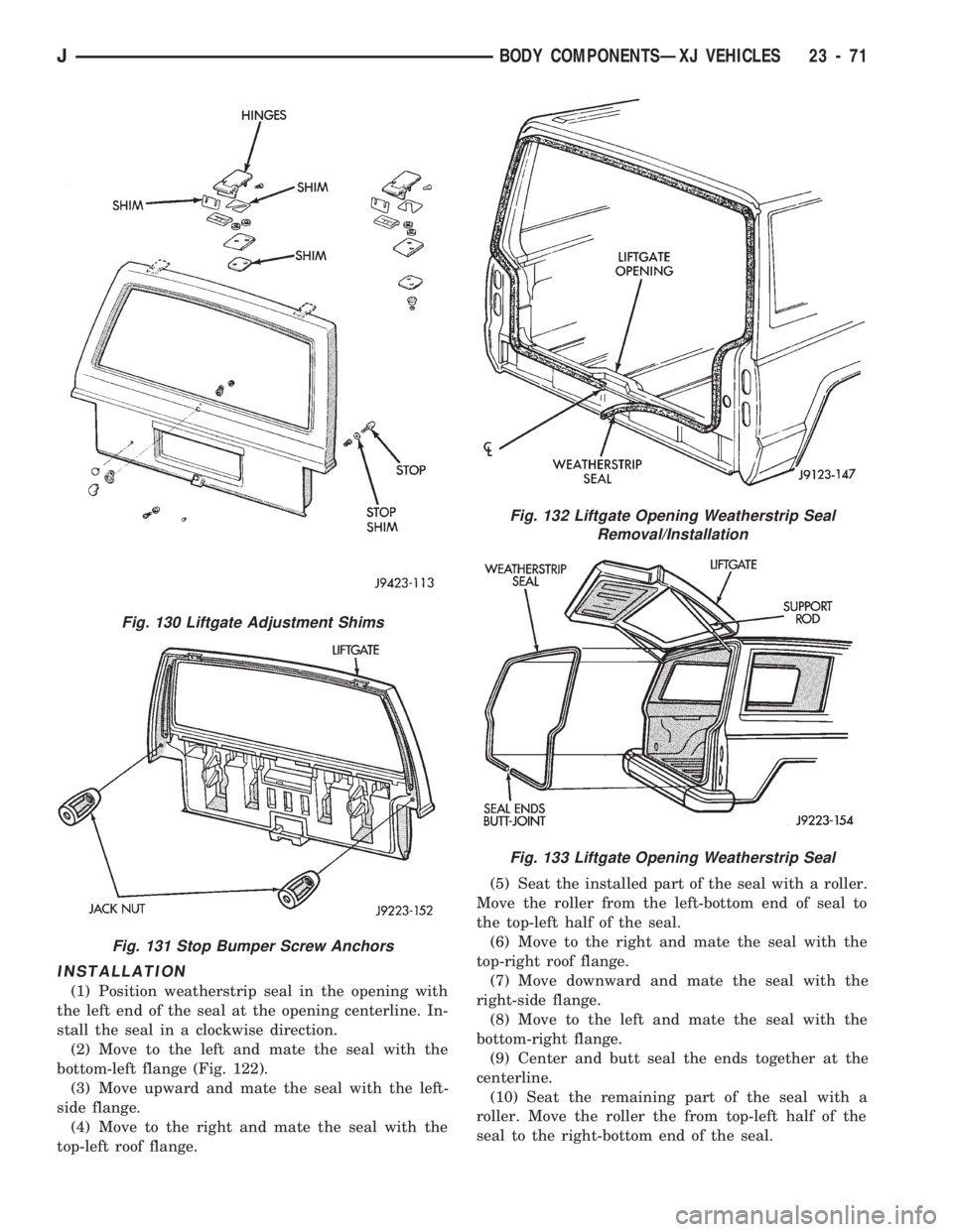
(1) Position weatherstrip seal in the opening with
the left end of the seal at the opening centerline. In-
stall the seal in a clockwise direction.
(2) Move to the left and mate the seal with the
bottom-left flange (Fig. 122).
(3) Move upward and mate the seal with the left-
side flange.
(4) Move to the right and mate the seal with the
top-left roof flange.(5) Seat the installed part of the seal with a roller.
Move the roller from the left-bottom end of seal to
the top-left half of the seal.
(6) Move to the right and mate the seal with the
top-right roof flange.
(7) Move downward and mate the seal with the
right-side flange.
(8) Move to the left and mate the seal with the
bottom-right flange.
(9) Center and butt seal the ends together at the
centerline.
(10) Seat the remaining part of the seal with a
roller. Move the roller the from top-left half of the
seal to the right-bottom end of the seal.
Fig. 130 Liftgate Adjustment Shims
Fig. 131 Stop Bumper Screw Anchors
Fig. 132 Liftgate Opening Weatherstrip Seal
Removal/Installation
Fig. 133 Liftgate Opening Weatherstrip Seal
JBODY COMPONENTSÐXJ VEHICLES 23 - 71
Page 1653 of 1784
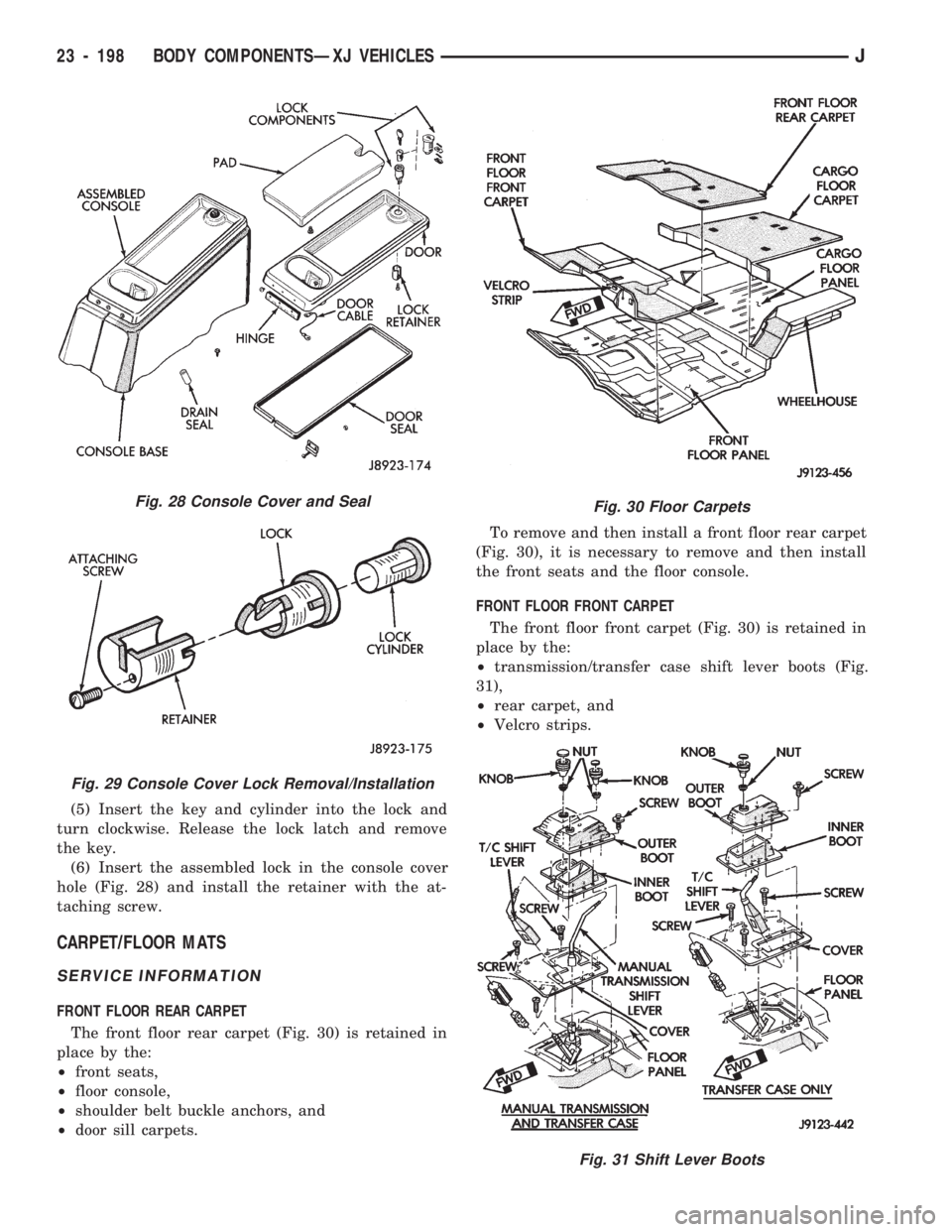
(5) Insert the key and cylinder into the lock and
turn clockwise. Release the lock latch and remove
the key.
(6) Insert the assembled lock in the console cover
hole (Fig. 28) and install the retainer with the at-
taching screw.
CARPET/FLOOR MATS
SERVICE INFORMATION
FRONT FLOOR REAR CARPET
The front floor rear carpet (Fig. 30) is retained in
place by the:
²front seats,
²floor console,
²shoulder belt buckle anchors, and
²door sill carpets.To remove and then install a front floor rear carpet
(Fig. 30), it is necessary to remove and then install
the front seats and the floor console.
FRONT FLOOR FRONT CARPET
The front floor front carpet (Fig. 30) is retained in
place by the:
²transmission/transfer case shift lever boots (Fig.
31),
²rear carpet, and
²Velcro strips.
Fig. 28 Console Cover and Seal
Fig. 29 Console Cover Lock Removal/Installation
Fig. 30 Floor Carpets
Fig. 31 Shift Lever Boots
23 - 198 BODY COMPONENTSÐXJ VEHICLESJ
Page 1666 of 1784
MANIFOLD
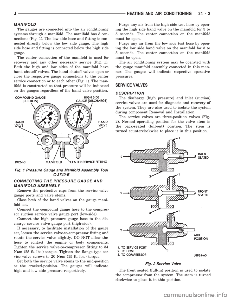
The gauges are connected into the air conditioning
systems through a manifold. The manifold has 3 con-
nections (Fig. 1). The low side hose and fitting is con-
nected directly below the low side gauge. The high
side hose and fitting is connected below the high side
gauge.
The center connection of the manifold is used for
recovery and any other necessary service (Fig. 1).
Both the high and low sides of the manifold have
hand shutoff valves. The hand shutoff valves open or
close the respective gauge connections to the center
service connection or to each other (Fig. 1). The man-
ifold is constructed so that pressure will be indicated
on the gauges regardless of the hand valve position.
CONNECTING THE PRESSURE GAUGE AND
MANIFOLD ASSEMBLY
Remove the protective caps from the service valve
gauge ports and valve stems.
Close both of the hand valves on the gauge mani-
fold set.
Connect the compound gauge hose to the compres-
sor suction service valve gauge port (low-side).
Connect the high pressure gauge hose to the dis-
charge service valve gauge port (high-side).
If necessary, to facilitate installation of the gauge
set, loosen the service valve-to-compressor fitting and
rotate the service valve slightly. DO NOT allow the
hose to contact the engine or body components.
Tighten the service valve-to-compressor fitting to 34
NIm (25 ft. lbs.) torque. Tighten the flange-type ser-
vice valve screws to 20 NIm (15 ft. lbs.) torque.
Set both the service valve stems to the mid-position
or the cracked-position. The gauges will indicate
high and low side pressure respectively.Purge any air from the high side test hose by open-
ing the high side hand valve on the manifold for 3 to
5 seconds. The center connection on the manifold
must be open.
Purge any air from the low side test hose by open-
ing the low side hand valve on the manifold for 3 to
5 seconds. The center connection on the manifold
must be open.
The air conditioning system may be operated with
the gauge manifold assembly connected in this man-
ner. The gauges will indicate respective operative
pressures.
SERVICE VALVES
DESCRIPTION
The discharge (high pressure) and inlet (suction)
service valves are used for diagnosis and recovery of
the system. They are also used to isolate the system
during component Removal and Installation.
The service valves are three-position valves (Fig.
2). Normal operating position for the valve stem is
the back-seated (full-out) position. The stem is
turned counterclockwise to place it in this position.
The front seated (full-in) position is used to isolate
the compressor from the system. The stem is turned
clockwise to place it in this position.
Fig. 1 Pressure Gauge and Manifold Assembly Tool
C-3740-B
Fig. 2 Service Valve
JHEATING AND AIR CONDITIONING 24 - 3
Page 1668 of 1784
(2) Close all the hand valves.
(3) Connect the red charging hose to the discharge
service valve.
(4) Connect the blue charging hose to the inlet
(suction) service valve.
(5) Discharge the system. Leave the suction and
discharge service valves in the mid-position.
CAUTION: The system must be completely dis-
charged into a recovery device before evacuating. If
the system is still charged, refrigerant can enter
and damage the vacuum pump.
(6) Connect the vacuum pump hose to the vacuum
pump inlet.
(7) Open the low and high pressure control valves
on the charging station.
(8) Start the vacuum pump. Open the vacuum con-
trol valve and note the vacuum reading.
(9) Test the system for leaks as follows:
²Close the manifold hand valves.
²Stop the vacuum pump and observe the vacuum
reading.
²If the system is leak-free, vacuum will hold steady
at the level indicated when the pump was stopped. If
vacuum remains steady for 3-5 minutes, resume and
continue evacuation for a minimum of 30 minutes.
²If the system has a leak, vacuum will fall off or
rapidly drop to a 0 reading. If a leak exists, partially
charge the system. Find and repair the leak and re-
sume evacuation.
(10) Continue evacuating the system for a mini-
mum of 30 minutes after attaining the lowest vac-
uum level.
(11) Fill the station charging cylinder while the
system is evacuating.
(12) Close the vacuum control valve and stop the
vacuum pump.
(13) Observe low pressure gauge to determine if a
system leak exists. If the system is leak-free, the sys-
tem is now ready for charging.
SYSTEM CHARGE
CHARGE CAPACITY
The recommended system charge is 1.1 kg (38 oz.)
of R-12 refrigerant for XJ vehicles and 0.9 kg (32 oz.)
for YJ vehicles.
Add an additional 28 grams (1 fluid oz.) of
compressor oil to the system when a hose, re-
ceiver-drier, condenser, expansion valve or
evaporator core is replaced.
PORTABLE SERVICE STATION
(1) Fill the station charging cylinder. Refrigerant
should be observed rising in the cylinder sight glass.
(2) Slightly open the valve at the top of the cylin-
der when pressure in the charging cylinder and re-frigerant supply tank are equal. This relieves head
pressure allowing refrigerant to continue filling the
cylinder.
(3) Observe the pressure gauge at the top of the
cylinder. Rotate the plastic cover on the cylinder un-
til the pressure heading column corresponds with the
gauge pressure in-line with the sight glass.
FOR EXAMPLE:ÐThe pressure gauge at the top
of the cylinder indicates 483 kPa (70 psi). Locate the
column with the pressure heading of 483 (70) and ro-
tate the cover so the 483 (70) column aligns with the
sight glass.
(4) When refrigerant reaches the correct level in
the sight glass, close the right hand valve at cylinder
base and on the refrigerant drum.
(5) Close the valve at the top of the charging cyl-
inder.
(6) Check for bubbles in the refrigerant using the
cylinder sight glass. If bubbles appear in the refrig-
erant, tilt the charging station rearward momen-
tarily.
(7) Connect the heating element cord to the power
pack receptacle and turn the heater switch ON.
(8) Allow the refrigerant to warm for about 10
minutes while the vacuum pump is operating.
WARNING: WEAR GOGGLES TO PROTECT THE
EYES.
(9) Discharge and evacuate the system.
(10) Close the low pressure valve on the charging
station.
(11) Fully open the left hand refrigerant control
valve at the base of the cylinder and the high pres-
sure valve on the charging station.
(12) Charge the system.
(13) Close the refrigerant control valve and the
high pressure valve on the charging station.
CAUTION: DO NOT permit the liquid level to drop
below 0 on the cylinder sight glass.
(14) Close the manifold gauges after completion of
the charging operation and check the high and low
side pressures.
(15) Check system operation.
CAUTION: DO NOT check system pressures until
the high and low pressure valves on the charging
station are closed. The low pressure gauge could
be damaged if the valves are open.
(16) Close all the valves on the charging station
and close the refrigerant drum valve when all the op-
erations are completed.
(17) Back-seat the service valves by turning them
fully counterclockwise. Install the quick seal caps on
the valves afterward.
JHEATING AND AIR CONDITIONING 24 - 5