1994 JEEP CHEROKEE clock
[x] Cancel search: clockPage 1060 of 1784
²SECOND - over-center preload adjustment
WORM THRUST BEARING PRELOAD
ADJUSTMENT
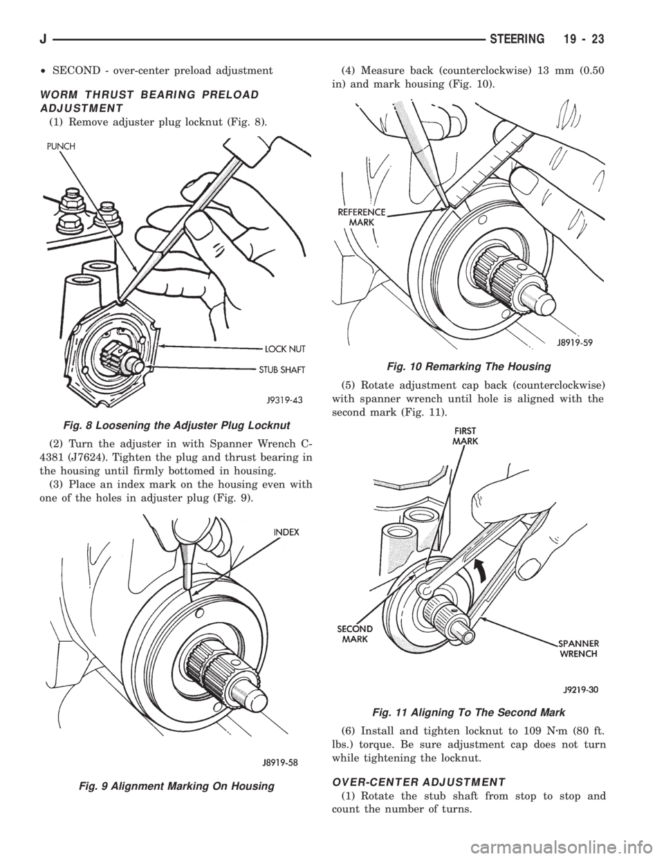
(1) Remove adjuster plug locknut (Fig. 8).
(2) Turn the adjuster in with Spanner Wrench C-
4381 (J7624). Tighten the plug and thrust bearing in
the housing until firmly bottomed in housing.
(3) Place an index mark on the housing even with
one of the holes in adjuster plug (Fig. 9).(4) Measure back (counterclockwise) 13 mm (0.50
in) and mark housing (Fig. 10).
(5) Rotate adjustment cap back (counterclockwise)
with spanner wrench until hole is aligned with the
second mark (Fig. 11).
(6) Install and tighten locknut to 109 Nzm (80 ft.
lbs.) torque. Be sure adjustment cap does not turn
while tightening the locknut.
OVER-CENTER ADJUSTMENT
(1) Rotate the stub shaft from stop to stop and
count the number of turns.
Fig. 10 Remarking The Housing
Fig. 11 Aligning To The Second Mark
Fig. 8 Loosening the Adjuster Plug Locknut
Fig. 9 Alignment Marking On Housing
JSTEERING 19 - 23
Page 1061 of 1784
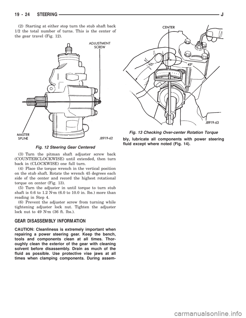
(2) Starting at either stop turn the stub shaft back
1/2 the total number of turns. This is the center of
the gear travel (Fig. 12).
(3) Turn the pitman shaft adjuster screw back
(COUNTERCLOCKWISE) until extended, then turn
back in (CLOCKWISE) one full turn.
(4) Place the torque wrench in the vertical position
on the stub shaft. Rotate the wrench 45 degrees each
side of the center and record the highest rotational
torque on center (Fig. 13).
(5) Turn the adjuster in until torque to turn stub
shaft is 0.6 to 1.2 Nzm (6.0 to 10.0 in. lbs.) more than
reading in Step 4.
(6) Prevent the adjuster screw from turning while
tightening adjuster lock nut. Tighten the adjuster
lock nut to 49 Nzm (36 ft. lbs.).
GEAR DISASSEMBLY INFORMATION
CAUTION: Cleanliness is extremely important when
repairing a power steering gear. Keep the bench,
tools and components clean at all times. Thor-
oughly clean the exterior of the gear with cleaning
solvent before disassembly. Drain as much of the
fluid as possible. Use protective vise jaws at all
times when clamping components. During assem-bly, lubricate all components with power steering
fluid except where noted (Fig. 14).
Fig. 13 Checking Over-center Rotation Torque
Fig. 12 Steering Gear Centered
19 - 24 STEERINGJ
Page 1063 of 1784
PITMAN SHAFT AND SIDE COVER REPLACEMENT
REMOVE
(1) Remove steering gear from vehicle. Refer to
Power Steering Gear Replacement in this section.
(2) Remove pitman arm from steering gear. Refer
to Pitman Arm Removal in the Steering Linkage sec-
tion.
(3) Rotate stub shaft back and forth to drain power
steering fluid.
DISASSEMBLE
²Clean exposed end of pitman shaft and housing.
²Clean pitman shaft spline with a wire brush.
(1) Remove preload adjuster nut.
(2) Rotate stub shaft with socket to center gear.
Remove side cover bolts.
(3) Remove side cover, gasket and pitman shaft as
an assembly.
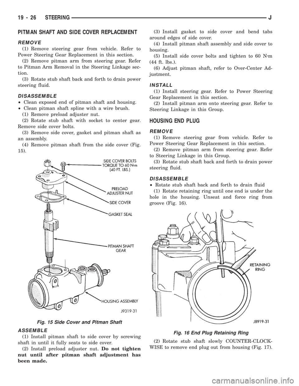
(4) Remove pitman shaft from the side cover (Fig.
15).
ASSEMBLE
(1) Install pitman shaft to side cover by screwing
shaft in until it fully seats to side cover.
(2) Install preload adjuster nut.Do not tighten
nut until after pitman shaft adjustment has
been made.(3) Install gasket to side cover and bend tabs
around edges of side cover.
(4) Install pitman shaft assembly and side cover to
housing.
(5) Install side cover bolts and tighten to 60 Nzm
(44 ft. lbs.).
(6) Adjust pitman shaft, refer to Over-Center Ad-
justment.
INSTALL
(1) Install steering gear. Refer to Power Steering
Gear Replacement in this section.
(2) Install pitman arm onto steering gear. Refer to
Steering Linkage in this Group.
HOUSING END PLUG
REMOVE
(1) Remove steering gear from vehicle. Refer to
Power Steering Gear Replacement in this section.
(2) Remove pitman arm from steering gear. Refer
to Steering Linkage in this Group.
(3) Rotate stub shaft back and forth to drain power
steering fluid.
DISASSEMBLE
²Rotate stub shaft back and forth to drain fluid
(1) Rotate retaining ring until one end is under the
hole in the housing. Unseat and force ring from
groove (Fig. 16).
(2) Rotate stub shaft slowly COUNTER-CLOCK-
WISE to remove end plug out from housing (Fig. 17).
Fig. 16 End Plug Retaining Ring
Fig. 15 Side Cover and Pitman Shaft
19 - 26 STEERINGJ
Page 1067 of 1784
(7) Install stub shaft and valve assembly to worm
shaft, fitting on worm shaft to slot in the valve as-
sembly.
(8) Adjust Thrust Bearing Preload Adjustment and
Over-Center Adjustment. Refer to Steering Gear Ad-
justments in this section.
INSTALL
(1) Install steering gear. Refer to Power Steering
Gear Replacement in this section.
RACK PISTON AND WORM SHAFT REPLACEMENT
REMOVE
(1) Remove steering gear from vehicle. Refer to
Power Steering Gear Replacement in this section.
DISASSEMBLE
(1) Remove pitman shaft and side cover. Refer to
Side Cover and Pitman Shaft Replacement in this
section.
(2) Remove housing plug end. Refer to Housing
End Plug Replacement in this section.
(3) Turn stub shaft COUNTERCLOCKWISE until
the rack piston begins to come out of the housing.
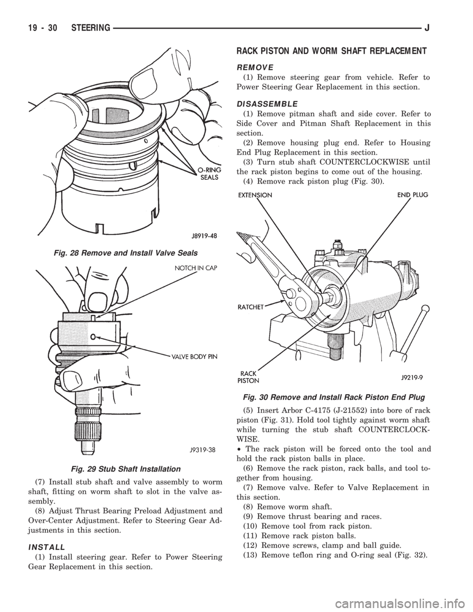
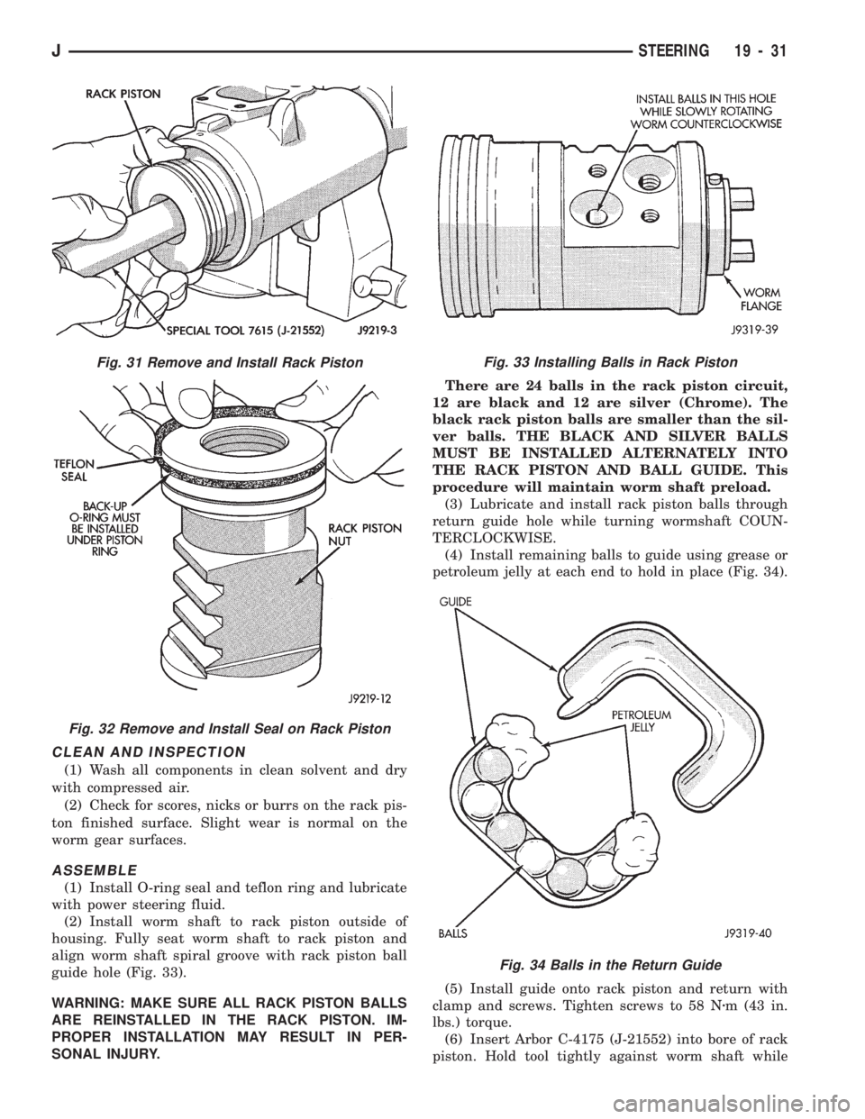
(4) Remove rack piston plug (Fig. 30).
(5) Insert Arbor C-4175 (J-21552) into bore of rack
piston (Fig. 31). Hold tool tightly against worm shaft
while turning the stub shaft COUNTERCLOCK-
WISE.
²The rack piston will be forced onto the tool and
hold the rack piston balls in place.
(6) Remove the rack piston, rack balls, and tool to-
gether from housing.
(7) Remove valve. Refer to Valve Replacement in
this section.
(8) Remove worm shaft.
(9) Remove thrust bearing and races.
(10) Remove tool from rack piston.
(11) Remove rack piston balls.
(12) Remove screws, clamp and ball guide.
(13) Remove teflon ring and O-ring seal (Fig. 32).
Fig. 28 Remove and Install Valve Seals
Fig. 29 Stub Shaft Installation
Fig. 30 Remove and Install Rack Piston End Plug
19 - 30 STEERINGJ
Page 1068 of 1784
CLEAN AND INSPECTION
(1) Wash all components in clean solvent and dry
with compressed air.
(2) Check for scores, nicks or burrs on the rack pis-
ton finished surface. Slight wear is normal on the
worm gear surfaces.
ASSEMBLE
(1) Install O-ring seal and teflon ring and lubricate
with power steering fluid.
(2) Install worm shaft to rack piston outside of
housing. Fully seat worm shaft to rack piston and
align worm shaft spiral groove with rack piston ball
guide hole (Fig. 33).
WARNING: MAKE SURE ALL RACK PISTON BALLS
ARE REINSTALLED IN THE RACK PISTON. IM-
PROPER INSTALLATION MAY RESULT IN PER-
SONAL INJURY.There are 24 balls in the rack piston circuit,
12 are black and 12 are silver (Chrome). The
black rack piston balls are smaller than the sil-
ver balls. THE BLACK AND SILVER BALLS
MUST BE INSTALLED ALTERNATELY INTO
THE RACK PISTON AND BALL GUIDE. This
procedure will maintain worm shaft preload.
(3) Lubricate and install rack piston balls through
return guide hole while turning wormshaft COUN-
TERCLOCKWISE.
(4) Install remaining balls to guide using grease or
petroleum jelly at each end to hold in place (Fig. 34).
(5) Install guide onto rack piston and return with
clamp and screws. Tighten screws to 58 Nzm (43 in.
lbs.) torque.
(6) Insert Arbor C-4175 (J-21552) into bore of rack
piston. Hold tool tightly against worm shaft while
Fig. 34 Balls in the Return Guide
Fig. 31 Remove and Install Rack Piston
Fig. 32 Remove and Install Seal on Rack Piston
Fig. 33 Installing Balls in Rack Piston
JSTEERING 19 - 31
Page 1069 of 1784
turning the stub shaft COUNTERCLOCKWISE.
²The rack piston will be forced onto the tool and
hold the rack piston balls in place.
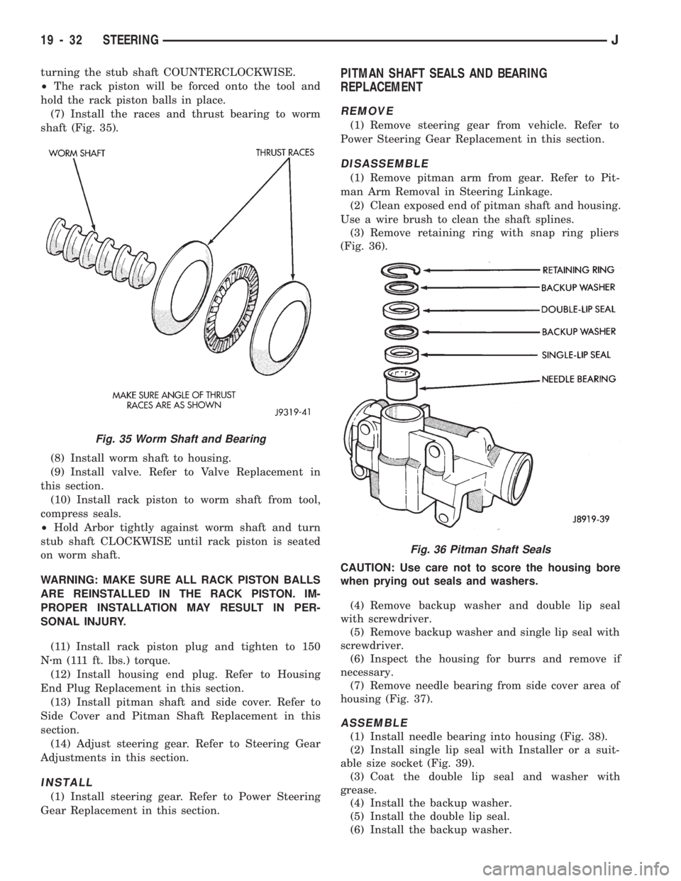
(7) Install the races and thrust bearing to worm
shaft (Fig. 35).
(8) Install worm shaft to housing.
(9) Install valve. Refer to Valve Replacement in
this section.
(10) Install rack piston to worm shaft from tool,
compress seals.
²Hold Arbor tightly against worm shaft and turn
stub shaft CLOCKWISE until rack piston is seated
on worm shaft.
WARNING: MAKE SURE ALL RACK PISTON BALLS
ARE REINSTALLED IN THE RACK PISTON. IM-
PROPER INSTALLATION MAY RESULT IN PER-
SONAL INJURY.
(11) Install rack piston plug and tighten to 150
Nzm (111 ft. lbs.) torque.
(12) Install housing end plug. Refer to Housing
End Plug Replacement in this section.
(13) Install pitman shaft and side cover. Refer to
Side Cover and Pitman Shaft Replacement in this
section.
(14) Adjust steering gear. Refer to Steering Gear
Adjustments in this section.
INSTALL
(1) Install steering gear. Refer to Power Steering
Gear Replacement in this section.
PITMAN SHAFT SEALS AND BEARING
REPLACEMENT
REMOVE
(1) Remove steering gear from vehicle. Refer to
Power Steering Gear Replacement in this section.
DISASSEMBLE
(1) Remove pitman arm from gear. Refer to Pit-
man Arm Removal in Steering Linkage.
(2) Clean exposed end of pitman shaft and housing.
Use a wire brush to clean the shaft splines.
(3) Remove retaining ring with snap ring pliers
(Fig. 36).
CAUTION: Use care not to score the housing bore
when prying out seals and washers.
(4) Remove backup washer and double lip seal
with screwdriver.
(5) Remove backup washer and single lip seal with
screwdriver.
(6) Inspect the housing for burrs and remove if
necessary.
(7) Remove needle bearing from side cover area of
housing (Fig. 37).
ASSEMBLE
(1) Install needle bearing into housing (Fig. 38).
(2) Install single lip seal with Installer or a suit-
able size socket (Fig. 39).
(3) Coat the double lip seal and washer with
grease.
(4) Install the backup washer.
(5) Install the double lip seal.
(6) Install the backup washer.
Fig. 36 Pitman Shaft Seals
Fig. 35 Worm Shaft and Bearing
19 - 32 STEERINGJ
Page 1079 of 1784
(7) Install the locknut on the wormshaft bearing
adjustment cap but do not tighten it at this time.
(8) Pack the steering gear housing with as much
chassis lubricant as possible.
Rotate the wormshaft in one direction until
the ball nut ceases. Pack the end of the housing
full of lubricant, rotate the shaft in the opposite
direction and repeat the packing procedure.
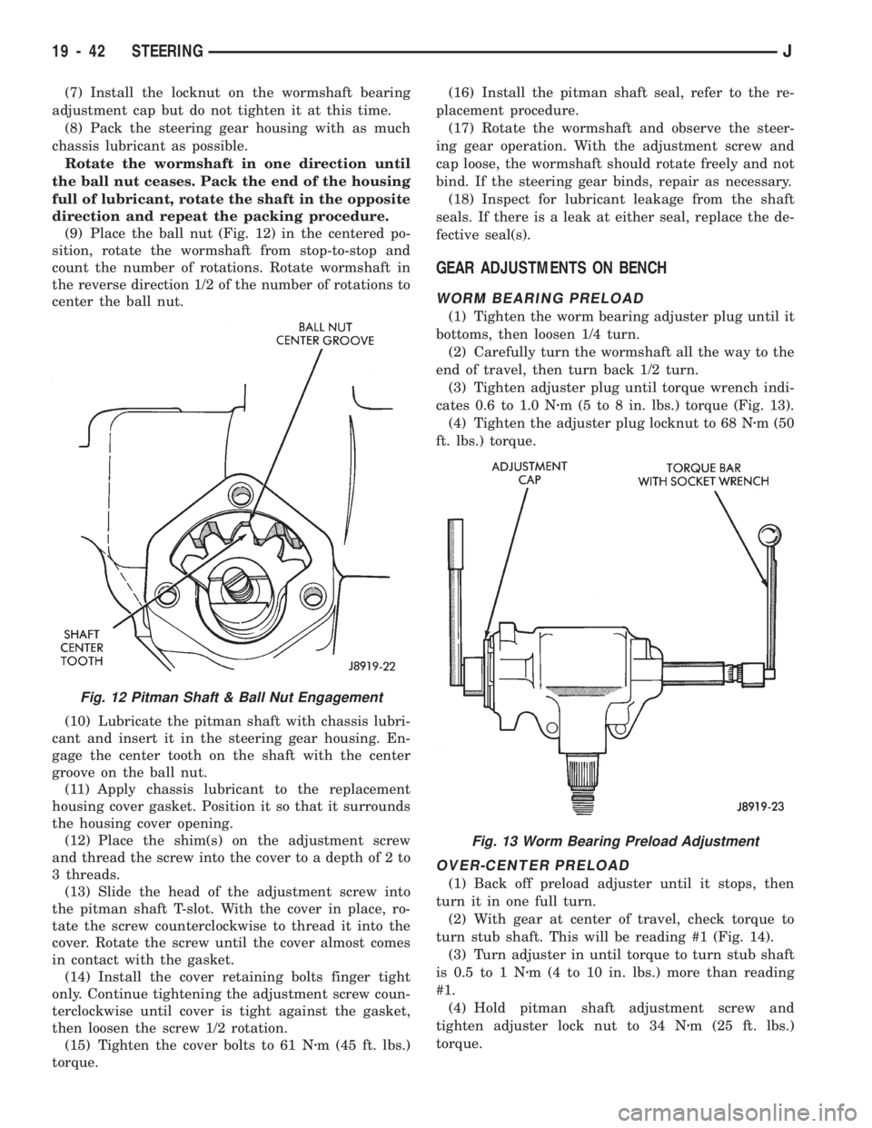
(9) Place the ball nut (Fig. 12) in the centered po-
sition, rotate the wormshaft from stop-to-stop and
count the number of rotations. Rotate wormshaft in
the reverse direction 1/2 of the number of rotations to
center the ball nut.
(10) Lubricate the pitman shaft with chassis lubri-
cant and insert it in the steering gear housing. En-
gage the center tooth on the shaft with the center
groove on the ball nut.
(11) Apply chassis lubricant to the replacement
housing cover gasket. Position it so that it surrounds
the housing cover opening.
(12) Place the shim(s) on the adjustment screw
and thread the screw into the cover to a depth of 2 to
3 threads.
(13) Slide the head of the adjustment screw into
the pitman shaft T-slot. With the cover in place, ro-
tate the screw counterclockwise to thread it into the
cover. Rotate the screw until the cover almost comes
in contact with the gasket.
(14) Install the cover retaining bolts finger tight
only. Continue tightening the adjustment screw coun-
terclockwise until cover is tight against the gasket,
then loosen the screw 1/2 rotation.
(15) Tighten the cover bolts to 61 Nzm (45 ft. lbs.)
torque.(16) Install the pitman shaft seal, refer to the re-
placement procedure.
(17) Rotate the wormshaft and observe the steer-
ing gear operation. With the adjustment screw and
cap loose, the wormshaft should rotate freely and not
bind. If the steering gear binds, repair as necessary.
(18) Inspect for lubricant leakage from the shaft
seals. If there is a leak at either seal, replace the de-
fective seal(s).
GEAR ADJUSTMENTS ON BENCH
WORM BEARING PRELOAD
(1) Tighten the worm bearing adjuster plug until it
bottoms, then loosen 1/4 turn.
(2) Carefully turn the wormshaft all the way to the
end of travel, then turn back 1/2 turn.
(3) Tighten adjuster plug until torque wrench indi-
cates 0.6 to 1.0 Nzm (5 to 8 in. lbs.) torque (Fig. 13).
(4) Tighten the adjuster plug locknut to 68 Nzm (50
ft. lbs.) torque.
OVER-CENTER PRELOAD
(1) Back off preload adjuster until it stops, then
turn it in one full turn.
(2) With gear at center of travel, check torque to
turn stub shaft. This will be reading #1 (Fig. 14).
(3) Turn adjuster in until torque to turn stub shaft
is 0.5 to 1 Nzm (4 to 10 in. lbs.) more than reading
#1.
(4) Hold pitman shaft adjustment screw and
tighten adjuster lock nut to 34 Nzm (25 ft. lbs.)
torque.
Fig. 12 Pitman Shaft & Ball Nut Engagement
Fig. 13 Worm Bearing Preload Adjustment
19 - 42 STEERINGJ
Page 1088 of 1784
(7) Remove the hazard warning switch knob. Press
the knob inward and remove it from the column by
turning it counterclockwise.
(8) Remove the turn signal/wiper/cruise control
stalk by pulling it out straight from the column.
Wiper must be in the off position.
(9) Disconnect the turn signal wire harness con-
nector from the bracket.
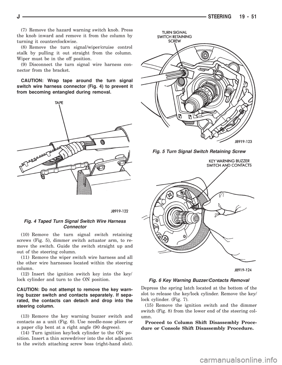
CAUTION: Wrap tape around the turn signal
switch wire harness connector (Fig. 4) to prevent it
from becoming entangled during removal.
(10) Remove the turn signal switch retaining
screws (Fig. 5), dimmer switch actuator arm, to re-
move the switch. Guide the switch straight up and
out of the steering column.
(11) Remove the wiper switch wire harness and all
the other wire harnesses located within the steering
column.
(12) Insert the ignition switch key into the key/
lock cylinder and turn to the ON position.
CAUTION: Do not attempt to remove the key warn-
ing buzzer switch and contacts separately. If sepa-
rated, the contacts can detach and drop into the
steering column.
(13) Remove the key warning buzzer switch and
contacts as a unit (Fig. 6). Use needle-nose pliers or
a paper clip bent at a right angle (90 degrees).
(14) Turn ignition key/lock cylinder to the ON po-
sition. Insert a thin screwdriver into the slot adjacent
to the switch attaching screw boss (right-hand slot).Depress the spring latch located at the bottom of the
slot to release the key/lock cylinder. Remove the key/
lock cylinder. (Fig. 7).
(15) Remove the ignition switch and the dimmer
switch (Fig. 8) from the lower end of the steering col-
umn.
Proceed to Column Shift Disassembly Proce-
dure or Console Shift Disassembly Procedure.
Fig. 4 Taped Turn Signal Switch Wire Harness
Connector
Fig. 5 Turn Signal Switch Retaining Screw
Fig. 6 Key Warning Buzzer/Contacts Removal
JSTEERING 19 - 51