1994 JEEP CHEROKEE clock
[x] Cancel search: clockPage 16 of 1784
ENGINE OIL CHANGE AND FILTER REPLACEMENT
WARNING: CARE SHOULD BE TAKEN WHEN
CHANGING OIL. PROTECTIVE CLOTHING AND
GLOVES SHOULD BE WORN. EXPOSED SKIN
SHOULD BE WASHED WITH SOAP AND WATER TO
REMOVE ANY ENGINE OIL. DO NOT USE GASO-
LINE, THINNER, OR SOLVENTS TO REMOVE EN-
GINE OIL FROM SKIN.
REQUIRED MAINTENANCE
With normal driving conditions, engine oil and fil-
ter must be changed after each 12 000-km (7,500-
miles)/12-month interval. If the vehicle is involved
with a severe driving condition, after each 4 800-km
(3,000-miles)/3-month interval. A severe driving con-
dition includes:
²frequent short trip driving less than 24 km (15
miles);
²frequent driving in a dusty environment;
²trailer towing;
²extensive engine idling;
²sustained high-speed operation;
²desert operation;
²frequent starting and stopping;
²cold-climate operation;
²off-road driving; or
²commercial service.
OIL CHANGE AND FILTER REPLACEMENT
(1) Drain the engine oil from the crankcase. Wait
until after the engine has attained the normal oper-
ating temperature to ensure complete drainage of oil.
(2) Install the drain-hole plug with a replacement
gasket.
The oil filter should be replaced during every
engine oil change.
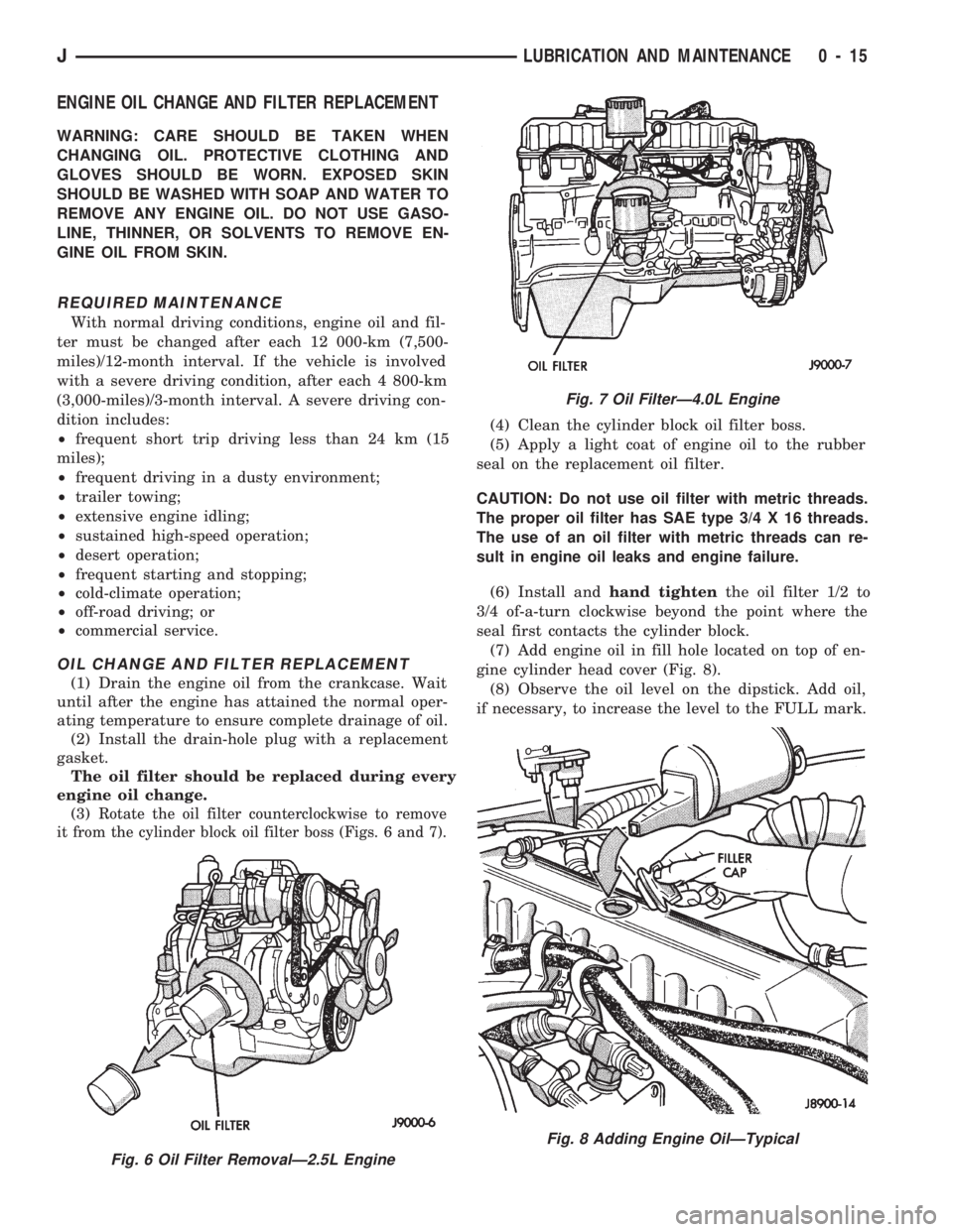
(3)
Rotate the oil filter counterclockwise to remove
it from the cylinder block oil filter boss (Figs. 6 and 7).
(4) Clean the cylinder block oil filter boss.
(5) Apply a light coat of engine oil to the rubber
seal on the replacement oil filter.
CAUTION: Do not use oil filter with metric threads.
The proper oil filter has SAE type 3/4 X 16 threads.
The use of an oil filter with metric threads can re-
sult in engine oil leaks and engine failure.
(6) Install andhand tightenthe oil filter 1/2 to
3/4 of-a-turn clockwise beyond the point where the
seal first contacts the cylinder block.
(7) Add engine oil in fill hole located on top of en-
gine cylinder head cover (Fig. 8).
(8) Observe the oil level on the dipstick. Add oil,
if necessary, to increase the level to the FULL mark.
Fig. 6 Oil Filter RemovalÐ2.5L Engine
Fig. 7 Oil FilterÐ4.0L Engine
Fig. 8 Adding Engine OilÐTypical
JLUBRICATION AND MAINTENANCE 0 - 15
Page 88 of 1784
WARNING: WRAP SHOP TOWELS AROUND FUEL
HOSES TO ABSORB ANY FUEL SPILLAGE DURING
FUEL TANK REMOVAL.
(5) Disconnect fuel vent supply and return tubes
from fittings on fuel pump module.
(6) Disconnect fuel pump module electrical harness
connector from main harness.
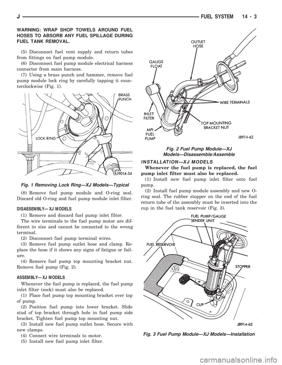
(7) Using a brass punch and hammer, remove fuel
pump module lock ring by carefully tapping it coun-
terclockwise (Fig. 1).
(8) Remove fuel pump module and O-ring seal.
Discard old O-ring and fuel pump module inlet filter.
DISASSEMBLYÐXJ MODELS
(1) Remove and discard fuel pump inlet filter.
The wire terminals to the fuel pump motor are dif-
ferent in size and cannot be connected to the wrong
terminal.
(2) Disconnect fuel pump terminal wires.
(3) Remove fuel pump outlet hose and clamp. Re-
place the hose if it shows any signs of fatigue or fail-
ure.
(4) Remove fuel pump top mounting bracket nut.
Remove fuel pump (Fig. 2).
ASSEMBLYÐXJ MODELS
Whenever the fuel pump is replaced, the fuel pump
inlet filter (sock) must also be replaced.
(1) Place fuel pump top mounting bracket over top
of pump.
(2) Position fuel pump into lower bracket. Slide
stud of top bracket through hole in fuel pump side
bracket. Tighten fuel pump top mounting nut.
(3) Install new fuel pump outlet hose. Secure with
new clamps.
(4) Connect wire terminals to motor.
(5) Install new fuel pump inlet filter.
INSTALLATIONÐXJ MODELS
Whenever the fuel pump is replaced, the fuel
pump inlet filter must also be replaced.
(1) Install new fuel pump inlet filter onto fuel
pump.
(2) Install fuel pump module assembly and new O-
ring seal. The rubber stopper on the end of the fuel
return tube of the assembly must be inserted into the
cup in the fuel tank reservoir (Fig. 3).
Fig. 1 Removing Lock RingÐXJ ModelsÐTypical
Fig. 2 Fuel Pump ModuleÐXJ
ModelsÐDisassemble/Assemble
Fig. 3 Fuel Pump ModuleÐXJ ModelsÐInstallation
JFUEL SYSTEM 14 - 3
Page 89 of 1784
(3) Using a brass punch and a hammer, install
lock ring. Carefully tap lock ring clockwise until it
seats against stop on fuel tank.
(4) Connect fuel supply and return hoses to fittings
on fuel pump module. Tighten hose clamps.
(5) Connect fuel pump module electrical harness
connector to main harness connector.
(6) Lower vehicle.
(7) Fill fuel tank. Install fuel tank cap.
(8) Connect negative battery cable.
(9) Start vehicle and inspect for leaks.
REMOVALÐYJ MODELS
The fuel tank must be removed to remove the fuel
pump module.
WARNING: THE FUEL SYSTEM IS UNDER A CON-
STANT PRESSURE (EVEN WITH THE ENGINE OFF).
BEFORE SERVICING THE FUEL PUMP MODULE,
THE FUEL SYSTEM PRESSURE MUST BE RE-
LEASED. REFER TO THE FUEL PRESSURE RE-
LEASE PROCEDURE IN THIS GROUP.
WARNING: EXTINGUISH ALL TOBACCO SMOKING
PRODUCTS BEFORE SERVICING THE FUEL SYS-
TEM. KEEP OPEN FLAME AWAY FROM FUEL SYS-
TEM COMPONENTS.
(1) Remove negative battery cable.
(2) Remove fuel filler cap. Perform the Fuel Pres-
sure Release Procedure as outlined in this group.
(3) Remove fuel tank. Refer to Fuel Tank Remov-
alÐYJ Models.
(4) Remove fuel pump module assembly.
(5) Remove mounting screws. Lift assembly and
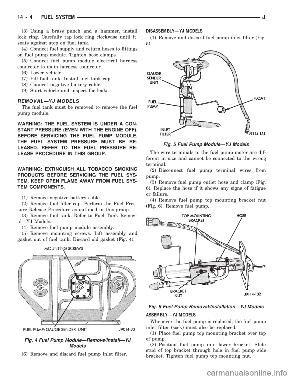
gasket out of fuel tank. Discard old gasket (Fig. 4).
(6) Remove and discard fuel pump inlet filter.DISASSEMBLYÐYJ MODELS
(1) Remove and discard fuel pump inlet filter (Fig.
5).
The wire terminals to the fuel pump motor are dif-
ferent in size and cannot be connected to the wrong
terminal.
(2) Disconnect fuel pump terminal wires from
pump.
(3) Remove fuel pump outlet hose and clamp (Fig.
6). Replace the hose if it shows any signs of fatigue
or failure.
(4) Remove fuel pump top mounting bracket nut
(Fig. 6). Remove fuel pump.
ASSEMBLYÐYJ MODELS
Whenever the fuel pump is replaced, the fuel pump
inlet filter (sock) must also be replaced.
(1) Place fuel pump top mounting bracket over top
of pump.
(2) Position fuel pump into lower bracket. Slide
stud of top bracket through hole in fuel pump side
bracket. Tighten fuel pump top mounting nut.
Fig. 4 Fuel Pump ModuleÐRemove/InstallÐYJ
Models
Fig. 5 Fuel Pump ModuleÐYJ Models
Fig. 6 Fuel Pump Removal/InstallationÐYJ Models
14 - 4 FUEL SYSTEMJ
Page 242 of 1784
SERVICE PROCEDURES
INDEX
page page
Coolant................................ 15
Coolant Reserve/Overflow System............ 19
Cooling System Cleaning/Reverse Flushing..... 17
Cooling System Fans..................... 26
Cooling System Hoses.................... 26
Draining Cooling System................... 16
Radiator Pressure Cap.................... 20
Radiators............................... 22Refilling Cooling System................... 17
Testing Cooling System for Leaks............ 18
Thermostat............................. 13
Transmission Oil Coolers................... 29
Water Pump Tests........................ 9
Water PumpsÐGeneral Information............ 9
Water PumpsÐRemoval/Installation........... 10
WATER PUMPSÐGENERAL INFORMATION
A centrifugal water pump circulates coolant
through the water jackets, passages, intake manifold,
radiator core, cooling system hoses and heater core.
The pump is driven from the engine crankshaft by a
drive belt on all engines.
The water pump impeller is pressed onto the rear
of a shaft that rotates in bearings pressed into the
housing. The housing has a small hole to allow seep-
age to escape. The water pump seals are lubricated
by the antifreeze in the coolant mixture. No addi-
tional lubrication is necessary.
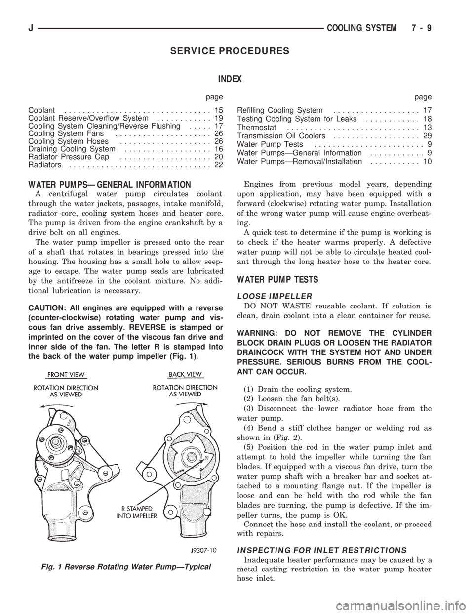
CAUTION: All engines are equipped with a reverse
(counter-clockwise) rotating water pump and vis-
cous fan drive assembly. REVERSE is stamped or
imprinted on the cover of the viscous fan drive and
inner side of the fan. The letter R is stamped into
the back of the water pump impeller (Fig. 1).Engines from previous model years, depending
upon application, may have been equipped with a
forward (clockwise) rotating water pump. Installation
of the wrong water pump will cause engine overheat-
ing.
A quick test to determine if the pump is working is
to check if the heater warms properly. A defective
water pump will not be able to circulate heated cool-
ant through the long heater hose to the heater core.
WATER PUMP TESTS
LOOSE IMPELLER
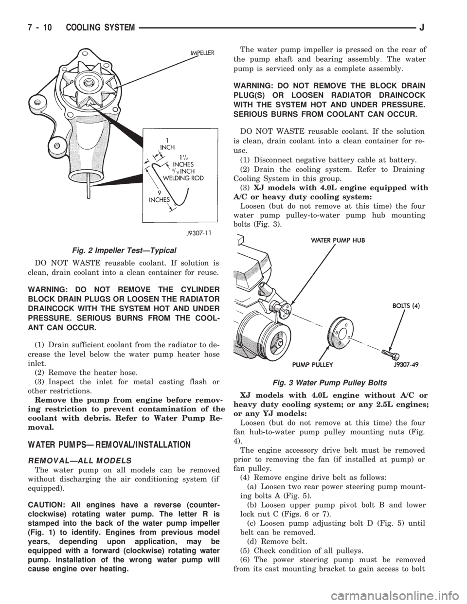
DO NOT WASTE reusable coolant. If solution is
clean, drain coolant into a clean container for reuse.
WARNING: DO NOT REMOVE THE CYLINDER
BLOCK DRAIN PLUGS OR LOOSEN THE RADIATOR
DRAINCOCK WITH THE SYSTEM HOT AND UNDER
PRESSURE. SERIOUS BURNS FROM THE COOL-
ANT CAN OCCUR.
(1) Drain the cooling system.
(2) Loosen the fan belt(s).
(3) Disconnect the lower radiator hose from the
water pump.
(4) Bend a stiff clothes hanger or welding rod as
shown in (Fig. 2).
(5) Position the rod in the water pump inlet and
attempt to hold the impeller while turning the fan
blades. If equipped with a viscous fan drive, turn the
water pump shaft with a breaker bar and socket at-
tached to a mounting flange nut. If the impeller is
loose and can be held with the rod while the fan
blades are turning, the pump is defective. If the im-
peller turns, the pump is OK.
Connect the hose and install the coolant, or proceed
with repairs.
INSPECTING FOR INLET RESTRICTIONS
Inadequate heater performance may be caused by a
metal casting restriction in the water pump heater
hose inlet.Fig. 1 Reverse Rotating Water PumpÐTypical
JCOOLING SYSTEM 7 - 9
Page 243 of 1784
DO NOT WASTE reusable coolant. If solution is
clean, drain coolant into a clean container for reuse.
WARNING: DO NOT REMOVE THE CYLINDER
BLOCK DRAIN PLUGS OR LOOSEN THE RADIATOR
DRAINCOCK WITH THE SYSTEM HOT AND UNDER
PRESSURE. SERIOUS BURNS FROM THE COOL-
ANT CAN OCCUR.
(1) Drain sufficient coolant from the radiator to de-
crease the level below the water pump heater hose
inlet.
(2) Remove the heater hose.
(3) Inspect the inlet for metal casting flash or
other restrictions.
Remove the pump from engine before remov-
ing restriction to prevent contamination of the
coolant with debris. Refer to Water Pump Re-
moval.
WATER PUMPSÐREMOVAL/INSTALLATION
REMOVALÐALL MODELS
The water pump on all models can be removed
without discharging the air conditioning system (if
equipped).
CAUTION: All engines have a reverse (counter-
clockwise) rotating water pump. The letter R is
stamped into the back of the water pump impeller
(Fig. 1) to identify. Engines from previous model
years, depending upon application, may be
equipped with a forward (clockwise) rotating water
pump. Installation of the wrong water pump will
cause engine over heating.The water pump impeller is pressed on the rear of
the pump shaft and bearing assembly. The water
pump is serviced only as a complete assembly.
WARNING: DO NOT REMOVE THE BLOCK DRAIN
PLUG(S) OR LOOSEN RADIATOR DRAINCOCK
WITH THE SYSTEM HOT AND UNDER PRESSURE.
SERIOUS BURNS FROM COOLANT CAN OCCUR.
DO NOT WASTE reusable coolant. If the solution
is clean, drain coolant into a clean container for re-
use.
(1) Disconnect negative battery cable at battery.
(2) Drain the cooling system. Refer to Draining
Cooling System in this group.
(3)XJ models with 4.0L engine equipped with
A/C or heavy duty cooling system:
Loosen (but do not remove at this time) the four
water pump pulley-to-water pump hub mounting
bolts (Fig. 3).
XJ models with 4.0L engine without A/C or
heavy duty cooling system; or any 2.5L engines;
or any YJ models:
Loosen (but do not remove at this time) the four
fan hub-to-water pump pulley mounting nuts (Fig.
4).
The engine accessory drive belt must be removed
prior to removing the fan (if installed at pump) or
fan pulley.
(4) Remove engine drive belt as follows:
(a) Loosen two rear power steering pump mount-
ing bolts A (Fig. 5).
(b) Loosen upper pump pivot bolt B and lower
lock nut C (Figs. 6 or 7).
(c) Loosen pump adjusting bolt D (Fig. 5) until
belt can be removed.
(d) Remove belt.
(5) Check condition of all pulleys.
(6) The power steering pump must be removed
from its cast mounting bracket to gain access to bolt
Fig. 2 Impeller TestÐTypical
Fig. 3 Water Pump Pulley Bolts
7 - 10 COOLING SYSTEMJ
Page 254 of 1784
RADIATOR CAP-TO-FILLER NECK
SEALÐPRESSURE RELIEF CHECK
With radiator cap installed on filler neck, remove
coolant reserve/ overflow tank hose from nipple on
filler neck. Connect a hand operated vacuum pump
to nipple. Operate pump until a reading of 47-to-61
kPa (14-to-18 in. Hg) appears on gauge. If the read-
ing stays steady, or drops slightly and then remains
steady, the pressure valve seal is good. Replace radi-
ator cap if reading does not hold.
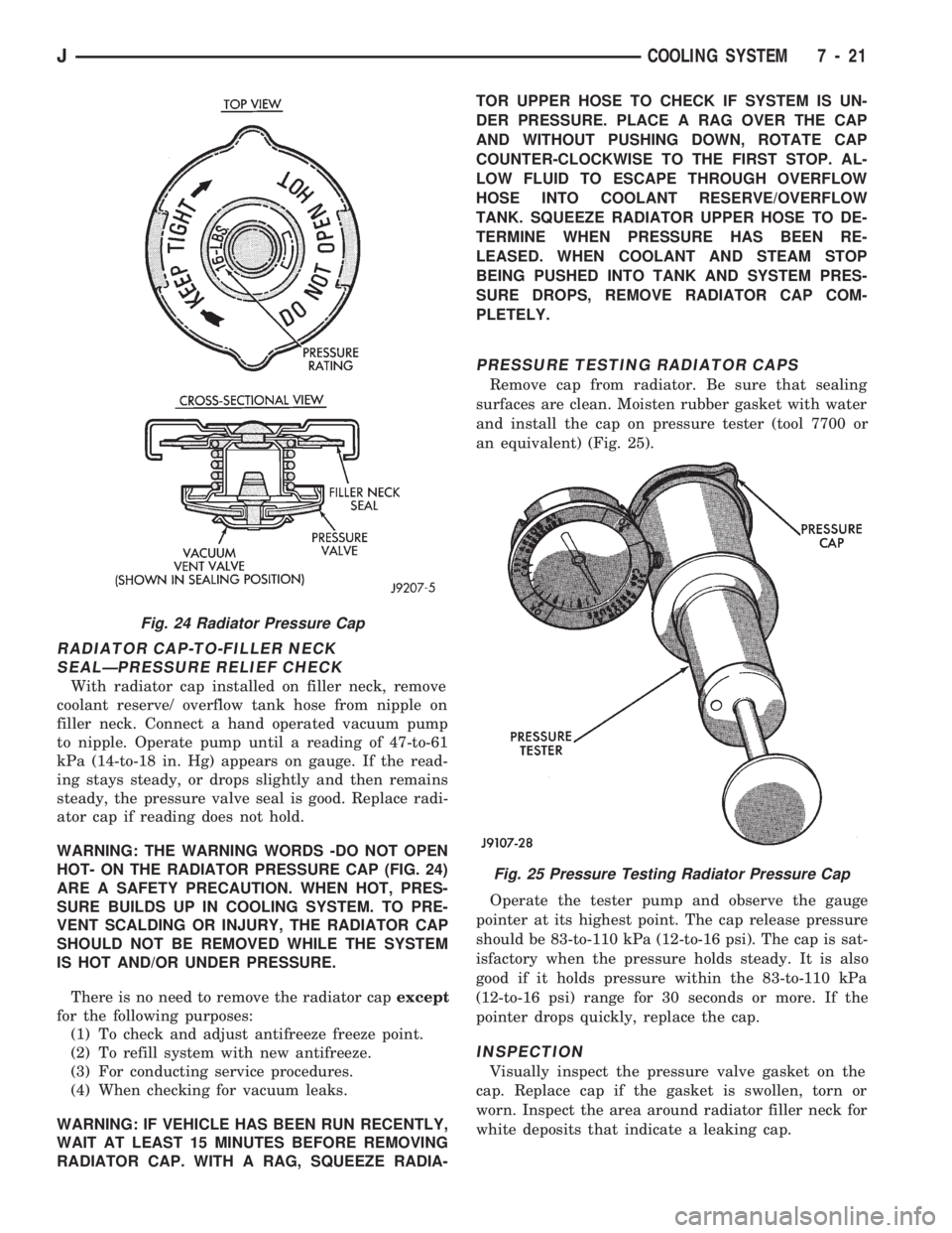
WARNING: THE WARNING WORDS -DO NOT OPEN
HOT- ON THE RADIATOR PRESSURE CAP (FIG. 24)
ARE A SAFETY PRECAUTION. WHEN HOT, PRES-
SURE BUILDS UP IN COOLING SYSTEM. TO PRE-
VENT SCALDING OR INJURY, THE RADIATOR CAP
SHOULD NOT BE REMOVED WHILE THE SYSTEM
IS HOT AND/OR UNDER PRESSURE.
There is no need to remove the radiator capexcept
for the following purposes:
(1) To check and adjust antifreeze freeze point.
(2) To refill system with new antifreeze.
(3) For conducting service procedures.
(4) When checking for vacuum leaks.
WARNING: IF VEHICLE HAS BEEN RUN RECENTLY,
WAIT AT LEAST 15 MINUTES BEFORE REMOVING
RADIATOR CAP. WITH A RAG, SQUEEZE RADIA-TOR UPPER HOSE TO CHECK IF SYSTEM IS UN-
DER PRESSURE. PLACE A RAG OVER THE CAP
AND WITHOUT PUSHING DOWN, ROTATE CAP
COUNTER-CLOCKWISE TO THE FIRST STOP. AL-
LOW FLUID TO ESCAPE THROUGH OVERFLOW
HOSE INTO COOLANT RESERVE/OVERFLOW
TANK. SQUEEZE RADIATOR UPPER HOSE TO DE-
TERMINE WHEN PRESSURE HAS BEEN RE-
LEASED. WHEN COOLANT AND STEAM STOP
BEING PUSHED INTO TANK AND SYSTEM PRES-
SURE DROPS, REMOVE RADIATOR CAP COM-
PLETELY.
PRESSURE TESTING RADIATOR CAPS
Remove cap from radiator. Be sure that sealing
surfaces are clean. Moisten rubber gasket with water
and install the cap on pressure tester (tool 7700 or
an equivalent) (Fig. 25).
Operate the tester pump and observe the gauge
pointer at its highest point. The cap release pressure
should be 83-to-110 kPa (12-to-16 psi). The cap is sat-
isfactory when the pressure holds steady. It is also
good if it holds pressure within the 83-to-110 kPa
(12-to-16 psi) range for 30 seconds or more. If the
pointer drops quickly, replace the cap.
INSPECTION
Visually inspect the pressure valve gasket on the
cap. Replace cap if the gasket is swollen, torn or
worn. Inspect the area around radiator filler neck for
white deposits that indicate a leaking cap.
Fig. 24 Radiator Pressure Cap
Fig. 25 Pressure Testing Radiator Pressure Cap
JCOOLING SYSTEM 7 - 21
Page 268 of 1784
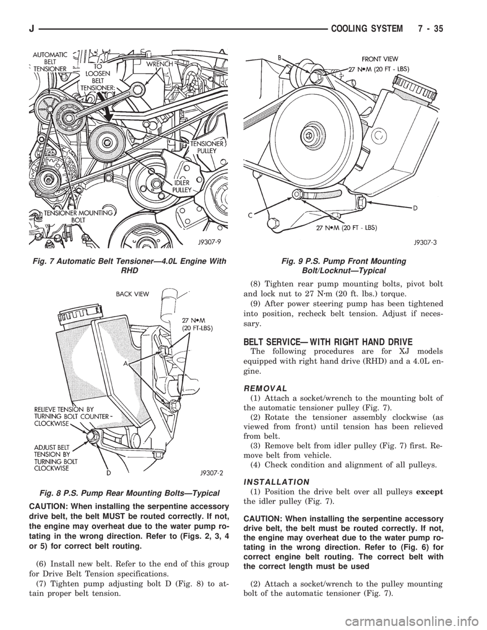
CAUTION: When installing the serpentine accessory
drive belt, the belt MUST be routed correctly. If not,
the engine may overheat due to the water pump ro-
tating in the wrong direction. Refer to (Figs. 2, 3, 4
or 5) for correct belt routing.
(6) Install new belt. Refer to the end of this group
for Drive Belt Tension specifications.
(7) Tighten pump adjusting bolt D (Fig. 8) to at-
tain proper belt tension.(8) Tighten rear pump mounting bolts, pivot bolt
and lock nut to 27 Nzm (20 ft. lbs.) torque.
(9) After power steering pump has been tightened
into position, recheck belt tension. Adjust if neces-
sary.
BELT SERVICEÐWITH RIGHT HAND DRIVE
The following procedures are for XJ models
equipped with right hand drive (RHD) and a 4.0L en-
gine.
REMOVAL
(1) Attach a socket/wrench to the mounting bolt of
the automatic tensioner pulley (Fig. 7).
(2) Rotate the tensioner assembly clockwise (as
viewed from front) until tension has been relieved
from belt.
(3) Remove belt from idler pulley (Fig. 7) first. Re-
move belt from vehicle.
(4) Check condition and alignment of all pulleys.
INSTALLATION
(1) Position the drive belt over all pulleysexcept
the idler pulley (Fig. 7).
CAUTION: When installing the serpentine accessory
drive belt, the belt must be routed correctly. If not,
the engine may overheat due to the water pump ro-
tating in the wrong direction. Refer to (Fig. 6) for
correct engine belt routing. The correct belt with
the correct length must be used
(2) Attach a socket/wrench to the pulley mounting
bolt of the automatic tensioner (Fig. 7).
Fig. 7 Automatic Belt TensionerÐ4.0L Engine With
RHD
Fig. 8 P.S. Pump Rear Mounting BoltsÐTypical
Fig. 9 P.S. Pump Front Mounting
Bolt/LocknutÐTypical
JCOOLING SYSTEM 7 - 35
Page 269 of 1784
(3) Rotate the socket/wrench clockwise (Fig. 7).
Place the belt over the idler pulley. Let tensioner ro-
tate back into place. Remove wrench. Be sure belt is
properly seated in the grooves of all pulleys.
AUTOMATIC BELT TENSIONERÐXJ MODELS
4.0L ENGINE WITH RIGHT HAND DRIVE
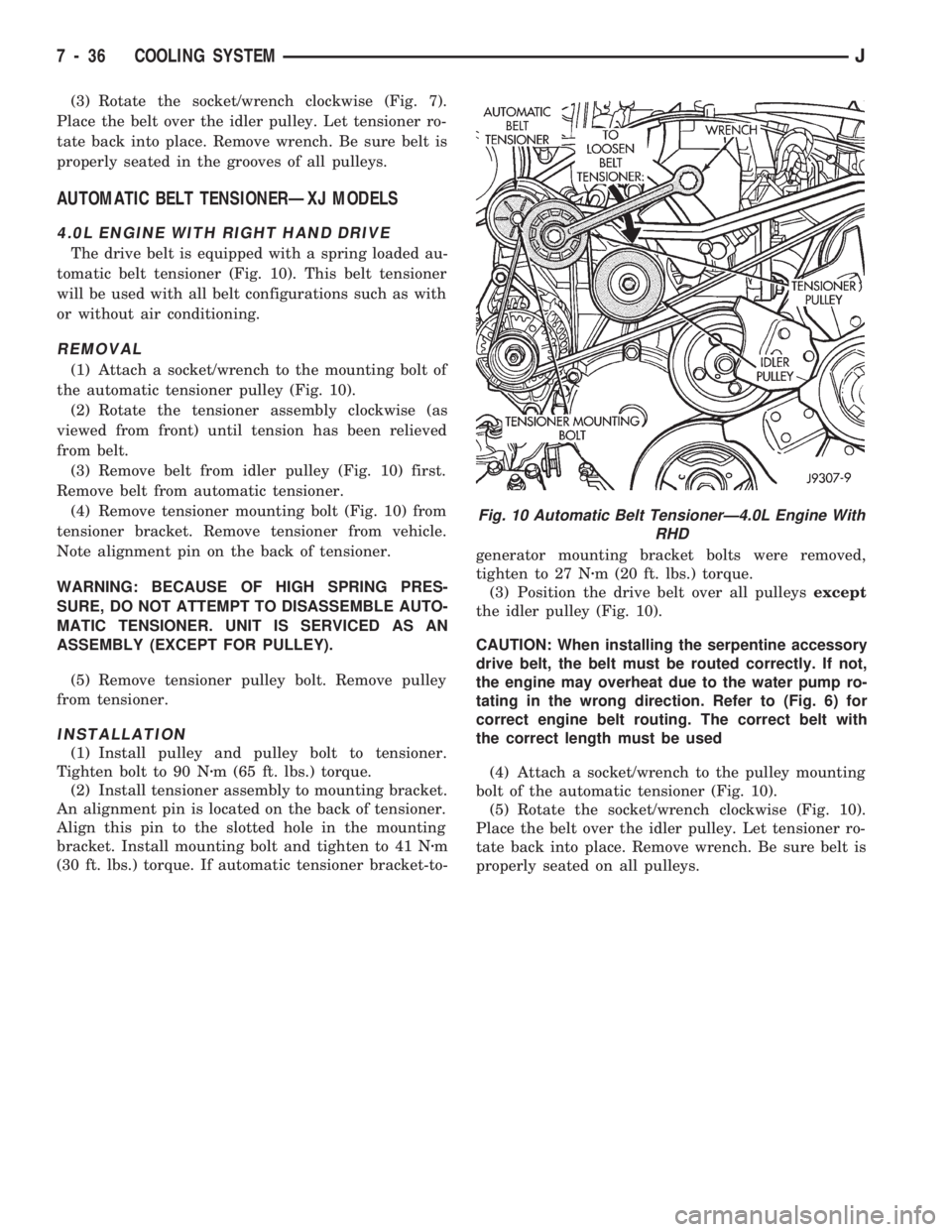
The drive belt is equipped with a spring loaded au-
tomatic belt tensioner (Fig. 10). This belt tensioner
will be used with all belt configurations such as with
or without air conditioning.
REMOVAL
(1) Attach a socket/wrench to the mounting bolt of
the automatic tensioner pulley (Fig. 10).
(2) Rotate the tensioner assembly clockwise (as
viewed from front) until tension has been relieved
from belt.
(3) Remove belt from idler pulley (Fig. 10) first.
Remove belt from automatic tensioner.
(4) Remove tensioner mounting bolt (Fig. 10) from
tensioner bracket. Remove tensioner from vehicle.
Note alignment pin on the back of tensioner.
WARNING: BECAUSE OF HIGH SPRING PRES-
SURE, DO NOT ATTEMPT TO DISASSEMBLE AUTO-
MATIC TENSIONER. UNIT IS SERVICED AS AN
ASSEMBLY (EXCEPT FOR PULLEY).
(5) Remove tensioner pulley bolt. Remove pulley
from tensioner.
INSTALLATION
(1) Install pulley and pulley bolt to tensioner.
Tighten bolt to 90 Nzm (65 ft. lbs.) torque.
(2) Install tensioner assembly to mounting bracket.
An alignment pin is located on the back of tensioner.
Align this pin to the slotted hole in the mounting
bracket. Install mounting bolt and tighten to 41 Nzm
(30 ft. lbs.) torque. If automatic tensioner bracket-to-generator mounting bracket bolts were removed,
tighten to 27 Nzm (20 ft. lbs.) torque.
(3) Position the drive belt over all pulleysexcept
the idler pulley (Fig. 10).
CAUTION: When installing the serpentine accessory
drive belt, the belt must be routed correctly. If not,
the engine may overheat due to the water pump ro-
tating in the wrong direction. Refer to (Fig. 6) for
correct engine belt routing. The correct belt with
the correct length must be used
(4) Attach a socket/wrench to the pulley mounting
bolt of the automatic tensioner (Fig. 10).
(5) Rotate the socket/wrench clockwise (Fig. 10).
Place the belt over the idler pulley. Let tensioner ro-
tate back into place. Remove wrench. Be sure belt is
properly seated on all pulleys.
Fig. 10 Automatic Belt TensionerÐ4.0L Engine With
RHD
7 - 36 COOLING SYSTEMJ