1994 JEEP CHEROKEE clock
[x] Cancel search: clockPage 281 of 1784
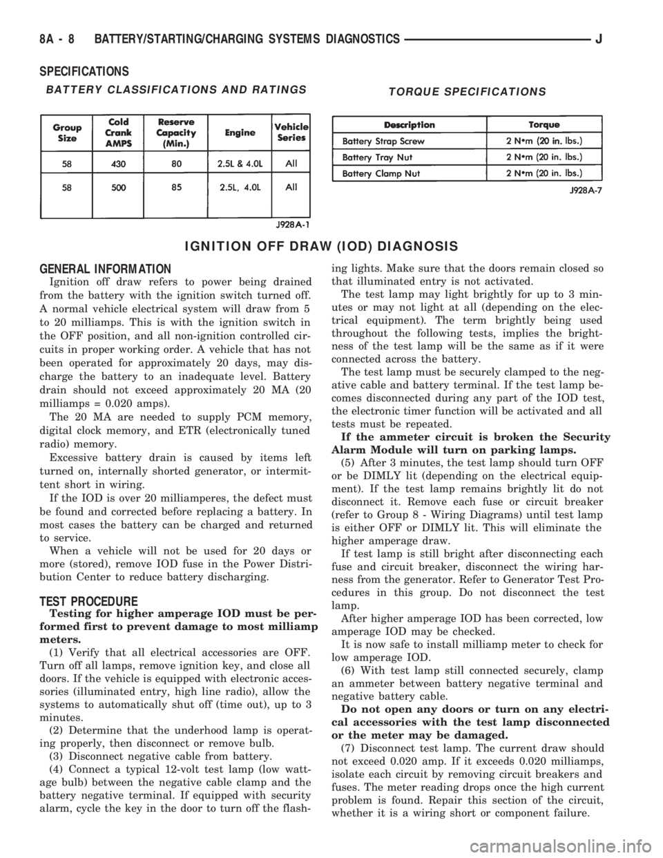
SPECIFICATIONS
IGNITION OFF DRAW (IOD) DIAGNOSIS
GENERAL INFORMATION
Ignition off draw refers to power being drained
from the battery with the ignition switch turned off.
A normal vehicle electrical system will draw from 5
to 20 milliamps. This is with the ignition switch in
the OFF position, and all non-ignition controlled cir-
cuits in proper working order. A vehicle that has not
been operated for approximately 20 days, may dis-
charge the battery to an inadequate level. Battery
drain should not exceed approximately 20 MA (20
milliamps = 0.020 amps).
The 20 MA are needed to supply PCM memory,
digital clock memory, and ETR (electronically tuned
radio) memory.
Excessive battery drain is caused by items left
turned on, internally shorted generator, or intermit-
tent short in wiring.
If the IOD is over 20 milliamperes, the defect must
be found and corrected before replacing a battery. In
most cases the battery can be charged and returned
to service.
When a vehicle will not be used for 20 days or
more (stored), remove IOD fuse in the Power Distri-
bution Center to reduce battery discharging.
TEST PROCEDURE
Testing for higher amperage IOD must be per-
formed first to prevent damage to most milliamp
meters.
(1) Verify that all electrical accessories are OFF.
Turn off all lamps, remove ignition key, and close all
doors. If the vehicle is equipped with electronic acces-
sories (illuminated entry, high line radio), allow the
systems to automatically shut off (time out), up to 3
minutes.
(2) Determine that the underhood lamp is operat-
ing properly, then disconnect or remove bulb.
(3) Disconnect negative cable from battery.
(4) Connect a typical 12-volt test lamp (low watt-
age bulb) between the negative cable clamp and the
battery negative terminal. If equipped with security
alarm, cycle the key in the door to turn off the flash-ing lights. Make sure that the doors remain closed so
that illuminated entry is not activated.
The test lamp may light brightly for up to 3 min-
utes or may not light at all (depending on the elec-
trical equipment). The term brightly being used
throughout the following tests, implies the bright-
ness of the test lamp will be the same as if it were
connected across the battery.
The test lamp must be securely clamped to the neg-
ative cable and battery terminal. If the test lamp be-
comes disconnected during any part of the IOD test,
the electronic timer function will be activated and all
tests must be repeated.
If the ammeter circuit is broken the Security
Alarm Module will turn on parking lamps.
(5) After 3 minutes, the test lamp should turn OFF
or be DIMLY lit (depending on the electrical equip-
ment). If the test lamp remains brightly lit do not
disconnect it. Remove each fuse or circuit breaker
(refer to Group 8 - Wiring Diagrams) until test lamp
is either OFF or DIMLY lit. This will eliminate the
higher amperage draw.
If test lamp is still bright after disconnecting each
fuse and circuit breaker, disconnect the wiring har-
ness from the generator. Refer to Generator Test Pro-
cedures in this group. Do not disconnect the test
lamp.
After higher amperage IOD has been corrected, low
amperage IOD may be checked.
It is now safe to install milliamp meter to check for
low amperage IOD.
(6) With test lamp still connected securely, clamp
an ammeter between battery negative terminal and
negative battery cable.
Do not open any doors or turn on any electri-
cal accessories with the test lamp disconnected
or the meter may be damaged.
(7) Disconnect test lamp. The current draw should
not exceed 0.020 amp. If it exceeds 0.020 milliamps,
isolate each circuit by removing circuit breakers and
fuses. The meter reading drops once the high current
problem is found. Repair this section of the circuit,
whether it is a wiring short or component failure.
BATTERY CLASSIFICATIONS AND RATINGSTORQUE SPECIFICATIONS
8A - 8 BATTERY/STARTING/CHARGING SYSTEMS DIAGNOSTICSJ
Page 321 of 1784

DIAGNOSTICS/SERVICE PROCEDURES
INDEX
page page
Automatic Shut Down (ASD) Relay............ 8
Camshaft Position Sensor Test............... 8
Crankshaft Position Sensor Test.............. 9
Distributor Cap........................... 9
Distributor Rotor......................... 10
DRB Scan Tool.......................... 10
Engine Coolant Temperature Sensor Test...... 12
General Information........................ 8
Ignition Coil............................. 11
Ignition Secondary Circuit Diagnosis.......... 12Ignition Timing........................... 14
Intake Manifold Air Temperature Sensor Test . . . 14
Manifold Absolute Pressure (MAP) Sensor Test . 14
On-Board Diagnostics (OBD)................ 19
Oxygen Sensor Tests..................... 19
Powertrain Control Module (PCM)............ 15
Spark Plug Secondary Cables............... 17
Spark Plugs............................ 16
Throttle Position Sensor Test............... 18
GENERAL INFORMATION
This section of the group, Diagnostics/Service Pro-
cedures, will discuss basic ignition system diagnos-
tics and service adjustments.
For system operation and component identification,
refer to the Component Identification/System Opera-
tion section of this group.
For removal or installation of ignition system com-
ponents, refer to the Component Removal/Installa-
tion section of this group.
For other useful information, refer to On-Board Di-
agnostics in the General Diagnosis sections of Group
14, Fuel System in this manual.
For operation of the DRB Scan Tool, refer to the
appropriate Powertrain Diagnostic Procedures ser-
vice manual.
AUTOMATIC SHUT DOWN (ASD) RELAY
Refer to RelaysÐOperation/Testing in the Group
14, Fuel System section of this service manual.
CAMSHAFT POSITION SENSOR TEST
The camshaft position sensor is located in the dis-
tributor on all engines.
To perform a complete test of this sensor and its
circuitry, refer to the DRB scan tool. Also refer to the
appropriate Powertrain Diagnostics Procedures man-
ual. To test the sensor only, refer to the following:
2.5L OR 4.0L ENGINE
For this test, an analog voltmeter is needed.Do
not remove the distributor connector from the dis-
tributor. Using small paper clips, insert them into
the backside of the distributor wire harness connec-
tor to make contact with the terminals. Be sure that
the connector is not damaged when inserting the pa-
per clips. Attach voltmeter leads to these paper clips.
(1) Connect the positive (+) voltmeter lead into
the sensor output wire. This is at done the distribu-
tor wire harness connector. For wire identification,
refer to Group 8W, Wiring Diagrams.(2) Connect the negative (-) voltmeter lead into the
ground wire. For wire identification, refer to Group
8W, Wiring Diagrams.
(3) Set the voltmeter to the 15 Volt DC scale.
(4) Remove distributor cap. Rotate (crank) engine
with starter until pulse ring (Fig. 1) enters the mag-
netic pickup on camshaft position sensor. Distributor
rotor should be pointed in 9 o'clock position. The
movable pulse ring should now be within the sensor
pickup.
(5) Turn ignition key to ON position. Voltmeter
should read approximately 5.0 volts.
(6) If voltage is not present, check the voltmeter
leads for a good connection.
(7) If voltage is still not present, check for voltage
at the supply wire. For wire identification, refer to
Group 8W, Wiring Diagrams.
Fig. 1 Pulse Ring/Rotor PositionÐTypical
8D - 8 IGNITION SYSTEMSJ
Page 336 of 1784
INSTALLATION
(1) Install coolant temperature sensor into the
thermostat housing. Tighten to 28 Nzm (21 ft. lbs.)
torque.
(2) Connect the wire connector.
(3) Fill the cooling system. Refer to group 7, Cool-
ing System.
DISTRIBUTOR
All distributors contain an internal oil seal that
prevents oil from entering the distributor housing.
The seal is not serviceable.
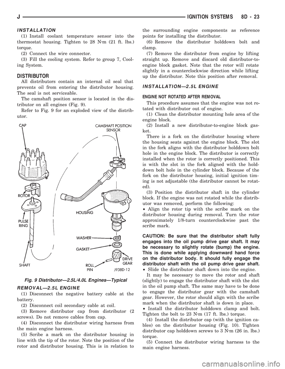
The camshaft position sensor is located in the dis-
tributor on all engines (Fig. 9).
Refer to Fig. 9 for an exploded view of the distrib-
utor.
REMOVALÐ2.5L ENGINE
(1) Disconnect the negative battery cable at the
battery.
(2) Disconnect coil secondary cable at coil.
(3) Remove distributor cap from distributor (2
screws). Do not remove cables from cap.
(4) Disconnect the distributor wiring harness from
the main engine harness.
(5) Scribe a mark on the distributor housing in
line with the tip of the rotor. Note the position of the
rotor and distributor housing. This is in relation tothe surrounding engine components as reference
points for installing the distributor.
(6) Remove the distributor holddown bolt and
clamp.
(7) Remove the distributor from engine by lifting
straight up. Remove and discard old distributor-to-
engine block gasket. Note that the rotor will rotate
slightly in a counterclockwise direction while lifting
up the distributor. Note this position after removal.
INSTALLATIONÐ2.5L ENGINE
ENGINE NOT ROTATED AFTER REMOVAL
This procedure assumes that the engine was not ro-
tated with distributor out of engine.
(1) Clean the distributor mounting hole area of the
engine block.
(2) Install a new distributor-to-engine block gas-
ket.
There is a fork on the distributor housing where
the housing seats against the engine block. The slot
in the fork aligns with the distributor holddown bolt
hole in the engine block. The distributor is correctly
installed when the rotor is correctly positioned. This
is with the slot in the fork aligned with the hold-
down bolt hole in the cylinder block. Because of the
fork on the distributor housing, initial ignition tim-
ing is not adjustable (the distributor cannot be rotat-
ed).
(3) Position the distributor shaft in the cylinder
block. If the engine was not rotated while the distrib-
utor was removed, perform the following:
²Align the rotor tip with the scribe mark on the
distributor housing during removal. Turn the rotor
approximately 1/8-turn counterclockwise past the
scribe mark.
CAUTION: Be sure that the distributor shaft fully
engages into the oil pump drive gear shaft. It may
be necessary to slightly rotate (bump) the engine.
This is done while applying downward hand force
on the distributor body. It should fully engage the
distributor shaft with the oil pump drive gear shaft.
²Slide the distributor shaft down into the engine.
It may be necessary to move the rotor and shaft
(slightly) to engage the distributor shaft with the slot
in the oil pump shaft. The same may have to be done
to engage the distributor gear with the camshaft
gear. However, the rotor should align with the scribe
mark when the distributor shaft is down in place.
²Install the distributor holddown clamp and bolt.
Tighten the bolt to 23 Nzm (17 ft. lbs.) torque.
(4) Install the distributor cap (with the ignition ca-
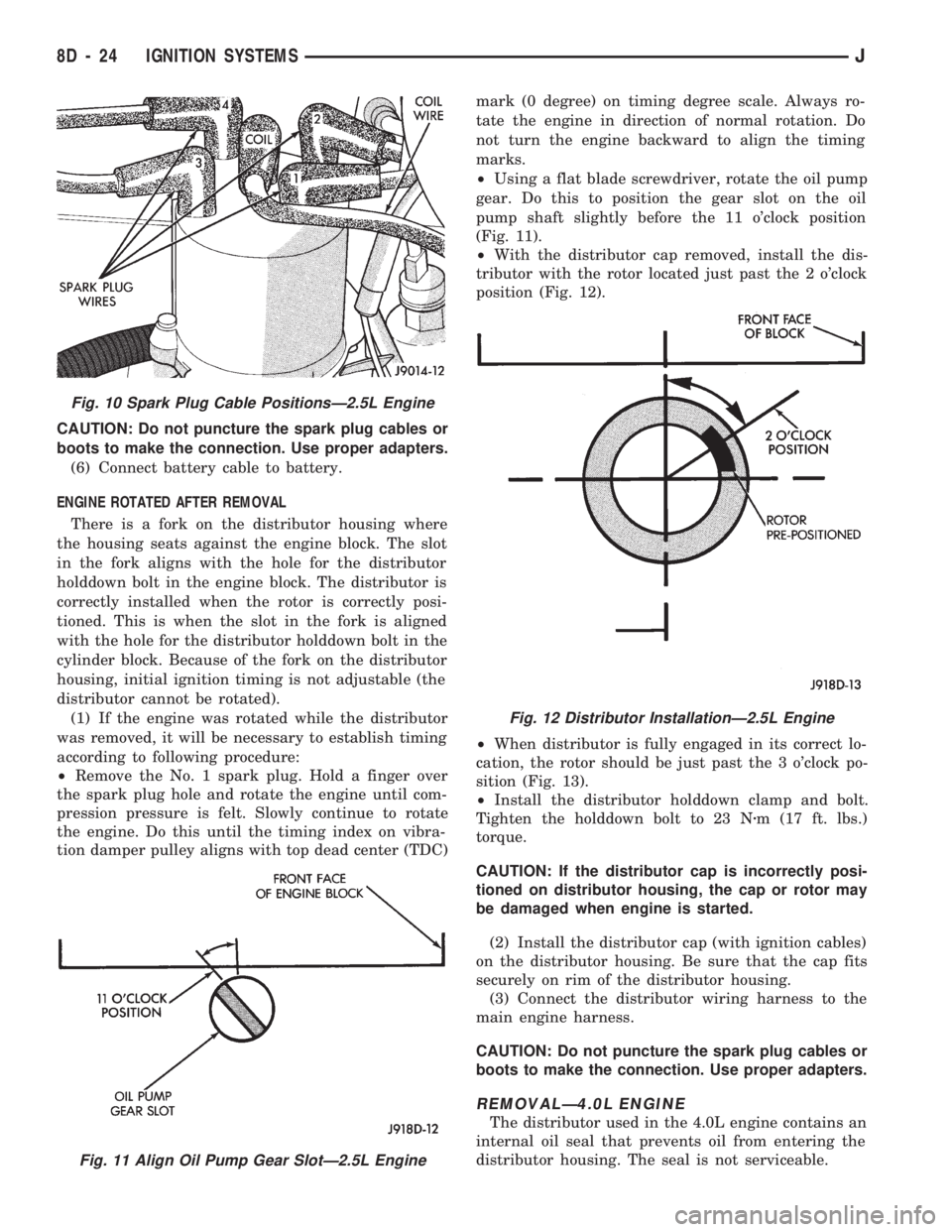
bles) on the distributor housing (Fig. 10). Tighten
distributor cap holddown screws to 3 Nzm (26 in. lbs.)
torque.
(5) Connect the distributor wiring harness to the
main engine harness.
Fig. 9 DistributorÐ2.5L/4.0L EnginesÐTypical
JIGNITION SYSTEMS 8D - 23
Page 337 of 1784
CAUTION: Do not puncture the spark plug cables or
boots to make the connection. Use proper adapters.
(6) Connect battery cable to battery.
ENGINE ROTATED AFTER REMOVAL
There is a fork on the distributor housing where
the housing seats against the engine block. The slot
in the fork aligns with the hole for the distributor
holddown bolt in the engine block. The distributor is
correctly installed when the rotor is correctly posi-
tioned. This is when the slot in the fork is aligned
with the hole for the distributor holddown bolt in the
cylinder block. Because of the fork on the distributor
housing, initial ignition timing is not adjustable (the
distributor cannot be rotated).
(1) If the engine was rotated while the distributor
was removed, it will be necessary to establish timing
according to following procedure:
²Remove the No. 1 spark plug. Hold a finger over
the spark plug hole and rotate the engine until com-
pression pressure is felt. Slowly continue to rotate
the engine. Do this until the timing index on vibra-
tion damper pulley aligns with top dead center (TDC)mark (0 degree) on timing degree scale. Always ro-
tate the engine in direction of normal rotation. Do
not turn the engine backward to align the timing
marks.
²Using a flat blade screwdriver, rotate the oil pump
gear. Do this to position the gear slot on the oil
pump shaft slightly before the 11 o'clock position
(Fig. 11).
²With the distributor cap removed, install the dis-
tributor with the rotor located just past the 2 o'clock
position (Fig. 12).
²When distributor is fully engaged in its correct lo-
cation, the rotor should be just past the 3 o'clock po-
sition (Fig. 13).
²Install the distributor holddown clamp and bolt.
Tighten the holddown bolt to 23 Nzm (17 ft. lbs.)
torque.
CAUTION: If the distributor cap is incorrectly posi-
tioned on distributor housing, the cap or rotor may
be damaged when engine is started.
(2) Install the distributor cap (with ignition cables)
on the distributor housing. Be sure that the cap fits
securely on rim of the distributor housing.
(3) Connect the distributor wiring harness to the
main engine harness.
CAUTION: Do not puncture the spark plug cables or
boots to make the connection. Use proper adapters.
REMOVALÐ4.0L ENGINE
The distributor used in the 4.0L engine contains an
internal oil seal that prevents oil from entering the
distributor housing. The seal is not serviceable.
Fig. 11 Align Oil Pump Gear SlotÐ2.5L Engine
Fig. 10 Spark Plug Cable PositionsÐ2.5L Engine
Fig. 12 Distributor InstallationÐ2.5L Engine
8D - 24 IGNITION SYSTEMSJ
Page 338 of 1784
The camshaft position sensor is located in the dis-
tributor on all engines (Fig. 9).
Refer to figure 9 for an exploded view of the dis-
tributor.
(1) Disconnect the negative battery cable at bat-
tery.
(2) On XJ models equipped with A/C, remove the
electrical cooling fan and shroud assembly from the
radiator. This will provide room to turn the engine
with a socket and ratchet using the vibration damper
bolt.
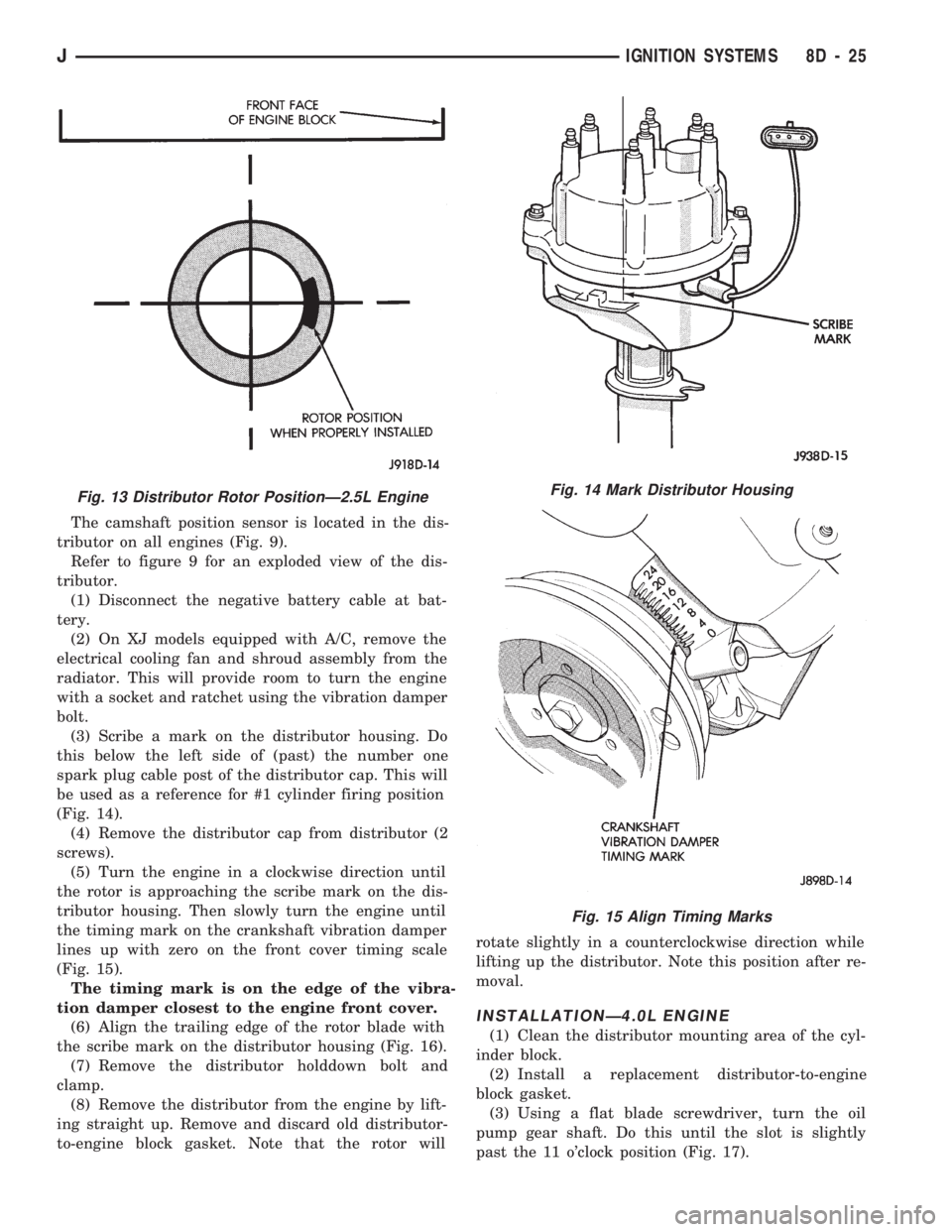
(3) Scribe a mark on the distributor housing. Do
this below the left side of (past) the number one
spark plug cable post of the distributor cap. This will
be used as a reference for #1 cylinder firing position
(Fig. 14).
(4) Remove the distributor cap from distributor (2
screws).
(5) Turn the engine in a clockwise direction until
the rotor is approaching the scribe mark on the dis-
tributor housing. Then slowly turn the engine until
the timing mark on the crankshaft vibration damper
lines up with zero on the front cover timing scale
(Fig. 15).
The timing mark is on the edge of the vibra-
tion damper closest to the engine front cover.
(6) Align the trailing edge of the rotor blade with
the scribe mark on the distributor housing (Fig. 16).
(7) Remove the distributor holddown bolt and
clamp.
(8) Remove the distributor from the engine by lift-
ing straight up. Remove and discard old distributor-
to-engine block gasket. Note that the rotor willrotate slightly in a counterclockwise direction while
lifting up the distributor. Note this position after re-
moval.
INSTALLATIONÐ4.0L ENGINE
(1) Clean the distributor mounting area of the cyl-
inder block.
(2) Install a replacement distributor-to-engine
block gasket.
(3) Using a flat blade screwdriver, turn the oil
pump gear shaft. Do this until the slot is slightly
past the 11 o'clock position (Fig. 17).
Fig. 13 Distributor Rotor PositionÐ2.5L EngineFig. 14 Mark Distributor Housing
Fig. 15 Align Timing Marks
JIGNITION SYSTEMS 8D - 25
Page 339 of 1784
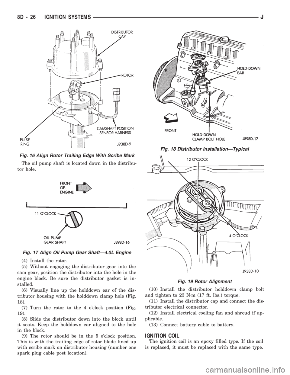
The oil pump shaft is located down in the distribu-
tor hole.
(4) Install the rotor.
(5) Without engaging the distributor gear into the
cam gear, position the distributor into the hole in the
engine block. Be sure the distributor gasket is in-
stalled.
(6) Visually line up the holddown ear of the dis-
tributor housing with the holddown clamp hole (Fig.
18).
(7) Turn the rotor to the 4 o'clock position (Fig.
19).
(8) Slide the distributor down into the block until
it seats. Keep the holddown ear aligned to the hole
in the block.
(9) The rotor should be in the 5 o'clock position.
This is with the trailing edge of rotor blade lined up
with scribe mark on distributor housing (number one
spark plug cable post location).(10) Install the distributor holddown clamp bolt
and tighten to 23 Nzm (17 ft. lbs.) torque.
(11) Install the distributor cap and connect the dis-
tributor electrical connector.
(12) Install electrical cooling fan and shroud if ap-
plicable.
(13) Connect battery cable to battery.
IGNITION COIL
The ignition coil is an epoxy filled type. If the coil
is replaced, it must be replaced with the same type.
Fig. 16 Align Rotor Trailing Edge With Scribe Mark
Fig. 17 Align Oil Pump Gear ShaftÐ4.0L Engine
Fig. 18 Distributor InstallationÐTypical
Fig. 19 Rotor Alignment
8D - 26 IGNITION SYSTEMSJ
Page 350 of 1784
INSTRUMENT CLUSTER DIAGNOSIS
INDEX
page page
4WD Indicator Inoperative................... 4
Anti-Lock Indicator......................... 4
Brake Indicator Inoperative.................. 4
Coolant Temperature Gauge Inoperative........ 3
Coolant Temperature Indicator Inoperative....... 3
Fuel Gauge Inoperative..................... 3
Gauges and Indicators Inoperative............ 3
Instrument Panel Lamps.................... 4
Low Fuel Warning Inoperative................ 4
Low Washer Indicator Inoperative............. 4Malfunction Indicator Lamp (Check Engine)...... 4
Oil Pressure Gauge Inoperative............... 3
Oil Pressure Indicator Inoperative............. 3
Radio/Clock Illumination.................... 4
Seat Belt Indicator........................ 4
Speedomete/Odometer Inoperative............. 3
Tachometer Inoperative..................... 3
Upshift Indicator Inoperative................. 4
Voltmeter Inoperative....................... 3
SPEEDOMETER/ODOMETER INOPERATIVE
(1) Check for continuity in the wire between the
vehicle speed sensor and cluster connector pin A5.
(2) With the ignition switch in the ON position,
check for battery voltage across pin A8 (B+) and pin
B2 (ground).
(3) Perform vehicle speed sensor test. Refer to the
appropriate vehicle Diagnostic Test Procedures man-
ual.
(4) If all the previous tests prove good, replace
speedometer/odometer.
GAUGES AND INDICATORS INOPERATIVE
(1) Remove and inspect fuse #17. Replace as re-
quired.
(2) Measure resistance at instrument cluster con-
nector terminal A3. Meter should read zero ohms. If
not, repair open to ground.
VOLTMETER INOPERATIVE
(1) Turn ignition switch to ON. Voltmeter should
read battery voltage. If not, go to step 2.
(2) Measure voltage at instrument cluster connec-
tor terminal A8. Meter should read battery voltage.
If OK, replace meter. If not, repair open to fuse #17.
OIL PRESSURE GAUGE INOPERATIVE
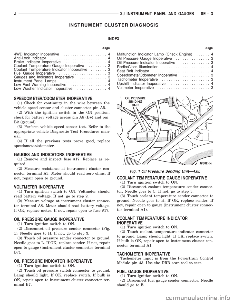
(1) Turn ignition switch to ON.
(2) Disconnect oil pressure sender connector (Fig.
1). Needle goes to H. If not, go to step 3.
(3) Touch oil pressure sender connector to ground.
Needle goes to L. If OK, replace sender. If not, repair
open to gauge (instrument cluster connector terminal
B7).
OIL PRESSURE INDICATOR INOPERATIVE
(1) Turn ignition switch to ON.
(2) Touch oil pressure switch connector to ground.
Lamp should light. If OK, replace switch. If bulb is
OK, repair open to instrument cluster connector ter-
minal B7.
COOLANT TEMPERATURE GAUGE INOPERATIVE
(1) Turn ignition switch to ON.
(2) Disconnect coolant temperature sender connec-
tor. Needle goes to C. If not, go to step 3.
(3) Touch coolant temperature sender connector to
ground. Needle goes to H. If OK, replace sender. If
not, repair open to gauge (instrument cluster connec-
tor terminal A1).
COOLANT TEMPERATURE INDICATOR
INOPERATIVE
(1) Turn ignition switch to ON.
(2) Touch coolant temperature indicator connector
to ground. Lamp should light. If OK, replace switch.
If bulb is OK, repair open to instrument cluster con-
nector terminal A1.
TACHOMETER INOPERATIVE
Tachometer input is from the Powertrain Control
Module pin 43. Use the DRB scan tool to test.
FUEL GAUGE INOPERATIVE
(1) Turn ignition switch to ON.
(2) Disconnect fuel gauge sender connector. Needle
should go to E.
Fig. 1 Oil Pressure Sending UnitÐ4.0L
JXJ INSTRUMENT PANEL AND GAUGES 8E - 3
Page 351 of 1784

(3) Connect a jumper between terminal A and B on
the body half of the fuel gauge sender connector. The
gauge should move to F. If gauge is OK, replace
sender. If not, go to step 4.
(4) Measure resistance of sender. Meter should
read 105 to 5 ohms. If OK, go to step 5. If not, re-
place sender.
(5) Check for an open between sender connector
and gauge. If OK, replace gauge. If not, repair open
to gauge.
LOW FUEL WARNING INOPERATIVE
(1) Turn ignition switch to ON.
(2) Disconnect terminal B1 of the instrument clus-
ter connector. Wait at least 10 seconds. Lamp (LED)
should light. If OK, replace sender. If not, replace
low fuel warning module.
UPSHIFT INDICATOR INOPERATIVE
(1) Turn ignition switch to ON.
(2) Ground pin 7 of connector B. Lamp should
light. If not, replace bulb. If OK, continue with
step 3.
(3) Turn ignition switch to OFF. Check for conti-
nuity between connector B pin 2 and pin 54 of the
Powertrain Control Module. If OK, replace PCM. If
not, repair open.
BRAKE INDICATOR INOPERATIVE
(1) Turn ignition switch to ON. Apply parking
brake, brake warning switch connector unplugged.
(2) Jumper brake warning switch connector termi-
nal B to ground. Lamp should light. If bulb is OK,
repair open to indicator.
(3) Turn ignition switch to OFF. Measure resis-
tance between brake warning switch connector ter-
minal A and ground. Meter should read zero ohms. If
OK, check switch and/or brake system. If not, repair
open to park brake switch ground.
4WD INDICATOR INOPERATIVE
(1) Apply parking brake, start engine, vehicle in
4WD Lock or 4WD.
(2) Unplug switch and touch harness side of wire
to ground. Lamp should light. If OK, check switch
operation, replace if bad. If bulb is OK, repair open
to indicator.
LOW WASHER INDICATOR INOPERATIVE
(1) Turn ignition switch to ON.
(2) Jumper 12 volts to fluid level switch connector
terminal B. Lamp should light. If not, go to step 3.
(3) Measure resistance between terminal B and
ground. Meter should read zero ohms. If not, repair
open to bulb. If OK, go to step 4.
(4) Measure voltage at fluid level switch connector
terminal A. Meter should read battery voltage. If
OK, replace switch. If not, repair open to fuse.
MALFUNCTION INDICATOR LAMP (CHECK ENGINE)
(1) Turn ignition switch to ON.
(2) Jumper Powertrain Control Module terminal 2
to ground. Lamp should light. If bulb is OK, check
for open to instrument cluster connector terminal 2.
ANTI-LOCK INDICATOR
(1) Turn ignition switch to ON.
(2) Jumper instrument cluster connector terminal
6 to ground. Lamp should light. If bulb is OK, check
wiring for an open to module. Refer to Group 5 -
Brakes.
SEAT BELT INDICATOR
Jumper instrument cluster connector terminal 15
to 12 volts. Lamp should light. If not, replace bulb. If
OK, check wiring for an open to buzzer module. Re-
fer to Group 8U - Chime/Buzzer Warning Systems.
RADIO/CLOCK ILLUMINATION
With the ignition switch in ACCESSORY or ON,
power comes from the radio fuse. It then goes
through the normally closed contacts of the radio il-
lumination relay to the radio at connector terminal
11.
Pulling the headlamp switch to ON energizes the
radio illumination relay. This closes the normally
open contacts of the relay, and the brightness for the
radio display is controlled by the headlamp switch
rheostat. The back-lighting for the radio is also con-
trolled by the headlamp rheostat through radio con-
nector terminal 10.
Refer to Group 8F - Audio Systems, for radio illu-
mination relay diagnosis.
INSTRUMENT PANEL LAMPS
Voltage is supplied at all times from the 40 amp
Maxi fuse (located in the Power Distribution Center)
through the park lamps fuse to the headlamp switch.
The circuit continues through the instrument lamps
fuse to the individual instrument panel lamps to
ground. Lamp brightness is controlled by turning the
headlamp switch knob.
DIAGNOSIS
(1) Turn parking lamps ON.
(2) Check park lamps fuse. Replace as required.
(3) Check instrument lamps fuse. Replace as re-
quired.
(4) Measure voltage at battery side of instrument
lamps fuse with rheostat turned counterclockwise to
clockwise (LO to HI). Meter should read zero volts to
battery voltage. If not, replace headlamp switch.
(5) Measure resistance at ground side of instru-
ment lamps fuse with parking lamps OFF. Meter
should read almost zero ohms (except bulb filament).
If not, repair open to ground. If zero ohms, 12 volt
supply wire from fuse is shorted to ground, repair short.
8E - 4 XJ INSTRUMENT PANEL AND GAUGESJ