1994 JEEP CHEROKEE clock
[x] Cancel search: clockPage 1109 of 1784
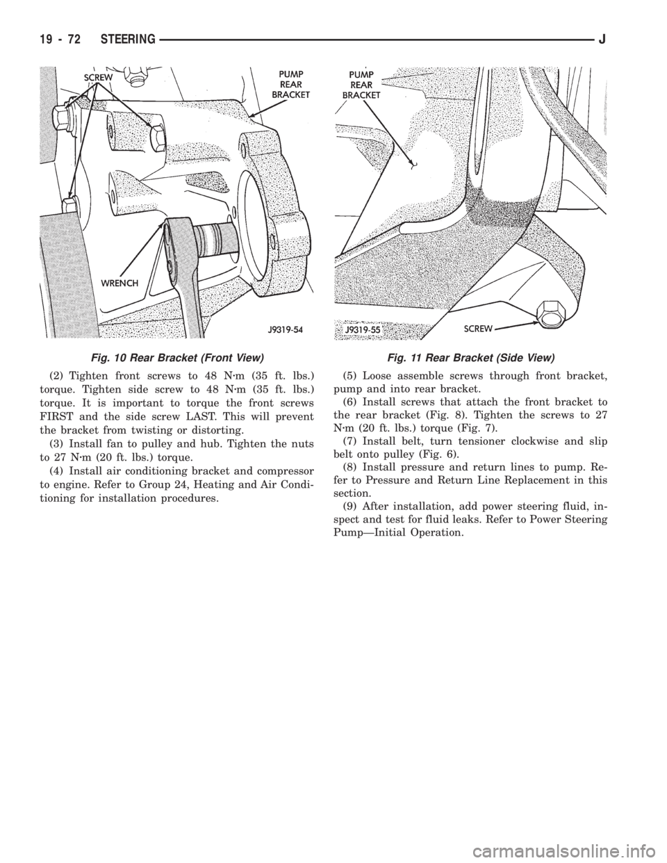
(2) Tighten front screws to 48 Nzm (35 ft. lbs.)
torque. Tighten side screw to 48 Nzm (35 ft. lbs.)
torque. It is important to torque the front screws
FIRST and the side screw LAST. This will prevent
the bracket from twisting or distorting.
(3) Install fan to pulley and hub. Tighten the nuts
to 27 Nzm (20 ft. lbs.) torque.
(4) Install air conditioning bracket and compressor
to engine. Refer to Group 24, Heating and Air Condi-
tioning for installation procedures.(5) Loose assemble screws through front bracket,
pump and into rear bracket.
(6) Install screws that attach the front bracket to
the rear bracket (Fig. 8). Tighten the screws to 27
Nzm (20 ft. lbs.) torque (Fig. 7).
(7) Install belt, turn tensioner clockwise and slip
belt onto pulley (Fig. 6).
(8) Install pressure and return lines to pump. Re-
fer to Pressure and Return Line Replacement in this
section.
(9) After installation, add power steering fluid, in-
spect and test for fluid leaks. Refer to Power Steering
PumpÐInitial Operation.
Fig. 11 Rear Bracket (Side View)Fig. 10 Rear Bracket (Front View)
19 - 72 STEERINGJ
Page 1115 of 1784
(6) Remove slave cylinder from clutch housing.
(7) Disconnect transmission shift lever as follows:
(a) Lower transmission-transfer case assembly ap-
proximately 7-8 cm (3 in.) for access to shift lever.
(b) Reach up and around transmission case and
unseat shift lever dust boot from transmission shift
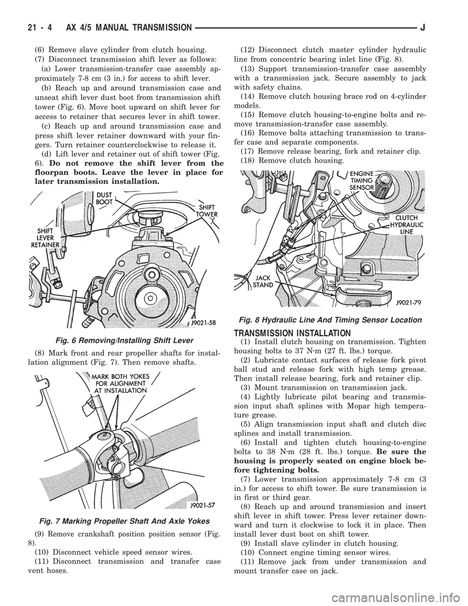
tower (Fig. 6). Move boot upward on shift lever for
access to retainer that secures lever in shift tower.
(c) Reach up and around transmission case and
press shift lever retainer downward with your fin-
gers. Turn retainer counterclockwise to release it.
(d) Lift lever and retainer out of shift tower (Fig.
6).Do not remove the shift lever from the
floorpan boots. Leave the lever in place for
later transmission installation.
(8) Mark front and rear propeller shafts for instal-
lation alignment (Fig. 7). Then remove shafts.
(9) Remove crankshaft position position sensor (Fig.
8).
(10) Disconnect vehicle speed sensor wires.
(11) Disconnect transmission and transfer case
vent hoses.(12) Disconnect clutch master cylinder hydraulic
line from concentric bearing inlet line (Fig. 8).
(13) Support transmission-transfer case assembly
with a transmission jack. Secure assembly to jack
with safety chains.
(14) Remove clutch housing brace rod on 4-cylinder
models.
(15) Remove clutch housing-to-engine bolts and re-
move transmission-transfer case assembly.
(16) Remove bolts attaching transmission to trans-
fer case and separate components.
(17) Remove release bearing, fork and retainer clip.
(18) Remove clutch housing.
TRANSMISSION INSTALLATION
(1) Install clutch housing on transmission. Tighten
housing bolts to 37 Nzm (27 ft. lbs.) torque.
(2) Lubricate contact surfaces of release fork pivot
ball stud and release fork with high temp grease.
Then install release bearing, fork and retainer clip.
(3) Mount transmission on transmission jack.
(4) Lightly lubricate pilot bearing and transmis-
sion input shaft splines with Mopar high tempera-
ture grease.
(5) Align transmission input shaft and clutch disc
splines and install transmission.
(6) Install and tighten clutch housing-to-engine
bolts to 38 Nzm (28 ft. lbs.) torque.Be sure the
housing is properly seated on engine block be-
fore tightening bolts.
(7) Lower transmission approximately 7-8 cm (3
in.) for access to shift tower. Be sure transmission is
in first or third gear.
(8) Reach up and around transmission and insert
shift lever in shift tower. Press lever retainer down-
ward and turn it clockwise to lock it in place. Then
install lever dust boot on shift tower.
(9) Install slave cylinder in clutch housing.
(10) Connect engine timing sensor wires.
(11) Remove jack from under transmission and
mount transfer case on jack.Fig. 6 Removing/Installing Shift Lever
Fig. 7 Marking Propeller Shaft And Axle Yokes
Fig. 8 Hydraulic Line And Timing Sensor Location
21 - 4 AX 4/5 MANUAL TRANSMISSIONJ
Page 1146 of 1784
(9) Reach up and around transmission case and
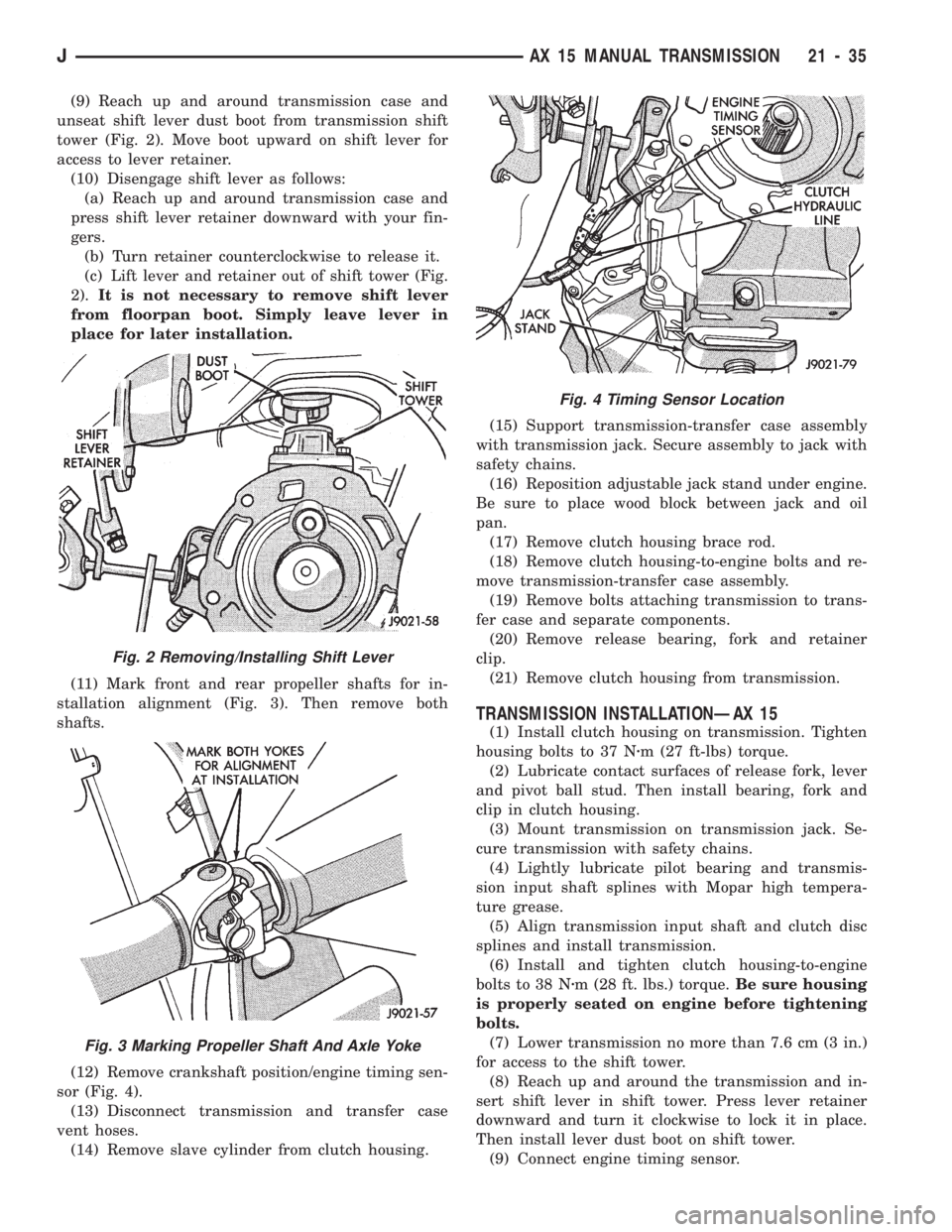
unseat shift lever dust boot from transmission shift
tower (Fig. 2). Move boot upward on shift lever for
access to lever retainer.
(10) Disengage shift lever as follows:
(a) Reach up and around transmission case and
press shift lever retainer downward with your fin-
gers.
(b) Turn retainer counterclockwise to release it.
(c) Lift lever and retainer out of shift tower (Fig.
2).It is not necessary to remove shift lever
from floorpan boot. Simply leave lever in
place for later installation.
(11) Mark front and rear propeller shafts for in-
stallation alignment (Fig. 3). Then remove both
shafts.
(12) Remove crankshaft position/engine timing sen-
sor (Fig. 4).
(13) Disconnect transmission and transfer case
vent hoses.
(14) Remove slave cylinder from clutch housing.(15) Support transmission-transfer case assembly
with transmission jack. Secure assembly to jack with
safety chains.
(16) Reposition adjustable jack stand under engine.
Be sure to place wood block between jack and oil
pan.
(17) Remove clutch housing brace rod.
(18) Remove clutch housing-to-engine bolts and re-
move transmission-transfer case assembly.
(19) Remove bolts attaching transmission to trans-
fer case and separate components.
(20) Remove release bearing, fork and retainer
clip.
(21) Remove clutch housing from transmission.
TRANSMISSION INSTALLATIONÐAX 15
(1) Install clutch housing on transmission. Tighten
housing bolts to 37 Nzm (27 ft-lbs) torque.
(2) Lubricate contact surfaces of release fork, lever
and pivot ball stud. Then install bearing, fork and
clip in clutch housing.
(3) Mount transmission on transmission jack. Se-
cure transmission with safety chains.
(4) Lightly lubricate pilot bearing and transmis-
sion input shaft splines with Mopar high tempera-
ture grease.
(5) Align transmission input shaft and clutch disc
splines and install transmission.
(6) Install and tighten clutch housing-to-engine
bolts to 38 Nzm (28 ft. lbs.) torque.Be sure housing
is properly seated on engine before tightening
bolts.
(7) Lower transmission no more than 7.6 cm (3 in.)
for access to the shift tower.
(8) Reach up and around the transmission and in-
sert shift lever in shift tower. Press lever retainer
downward and turn it clockwise to lock it in place.
Then install lever dust boot on shift tower.
(9) Connect engine timing sensor.
Fig. 2 Removing/Installing Shift Lever
Fig. 3 Marking Propeller Shaft And Axle Yoke
Fig. 4 Timing Sensor Location
JAX 15 MANUAL TRANSMISSION 21 - 35
Page 1215 of 1784
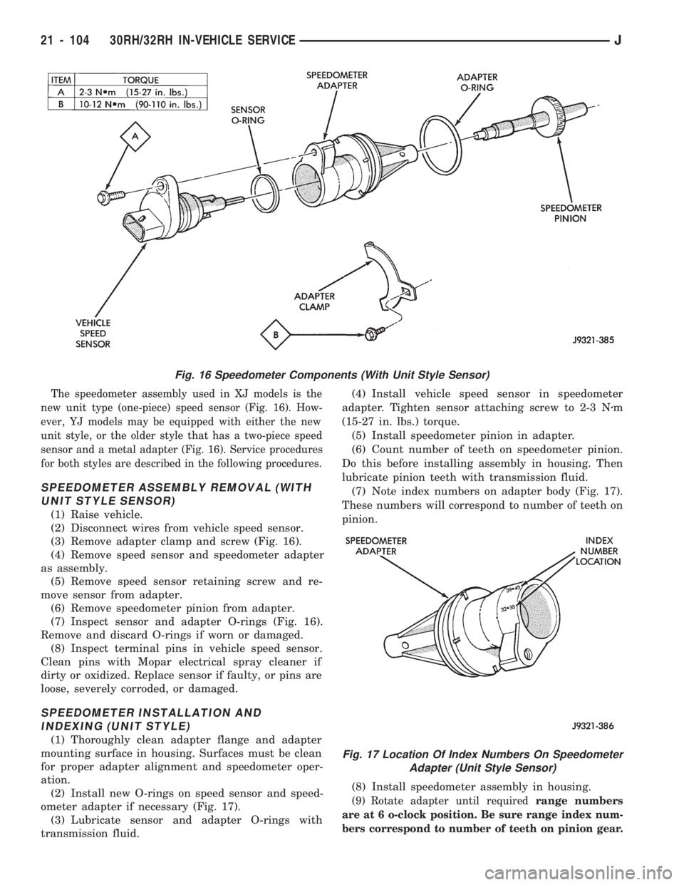
The speedometer assembly used in XJ models is the
new unit type (one-piece) speed sensor (Fig. 16). How-
ever, YJ models may be equipped with either the new
unit style, or the older style that has a two-piece speed
sensor and a metal adapter (Fig. 16). Service procedures
for both styles are described in the following procedures.
SPEEDOMETER ASSEMBLY REMOVAL (WITH
UNIT STYLE SENSOR)
(1) Raise vehicle.
(2) Disconnect wires from vehicle speed sensor.
(3) Remove adapter clamp and screw (Fig. 16).
(4) Remove speed sensor and speedometer adapter
as assembly.
(5) Remove speed sensor retaining screw and re-
move sensor from adapter.
(6) Remove speedometer pinion from adapter.
(7) Inspect sensor and adapter O-rings (Fig. 16).
Remove and discard O-rings if worn or damaged.
(8) Inspect terminal pins in vehicle speed sensor.
Clean pins with Mopar electrical spray cleaner if
dirty or oxidized. Replace sensor if faulty, or pins are
loose, severely corroded, or damaged.
SPEEDOMETER INSTALLATION AND
INDEXING (UNIT STYLE)
(1) Thoroughly clean adapter flange and adapter
mounting surface in housing. Surfaces must be clean
for proper adapter alignment and speedometer oper-
ation.
(2) Install new O-rings on speed sensor and speed-
ometer adapter if necessary (Fig. 17).
(3) Lubricate sensor and adapter O-rings with
transmission fluid.(4) Install vehicle speed sensor in speedometer
adapter. Tighten sensor attaching screw to 2-3 Nzm
(15-27 in. lbs.) torque.
(5) Install speedometer pinion in adapter.
(6) Count number of teeth on speedometer pinion.
Do this before installing assembly in housing. Then
lubricate pinion teeth with transmission fluid.
(7) Note index numbers on adapter body (Fig. 17).
These numbers will correspond to number of teeth on
pinion.
(8) Install speedometer assembly in housing.
(9) Rotate adapter until requiredrange numbers
are at 6 o-clock position. Be sure range index num-
bers correspond to number of teeth on pinion gear.
Fig. 16 Speedometer Components (With Unit Style Sensor)
Fig. 17 Location Of Index Numbers On Speedometer
Adapter (Unit Style Sensor)
21 - 104 30RH/32RH IN-VEHICLE SERVICEJ
Page 1216 of 1784
(10) Install speedometer adapter clamp and retain-
ing screw. Tighten clamp screw to 10-12 Nzm (90-110
in. lbs.) torque.
(11) Connect wires to vehicle speed sensor.
(12) Lower vehicle and top off transmission fluid
level if necessary.
SPEEDOMETER COMPONENT REMOVAL
(TWO-PIECE SENSOR)
(1) Raise vehicle.
(2) Disconnect speed sensor wires.
(3) Remove bolt attaching vehicle speed sensor to
sensor adapter. Then slide sensor out of adapter.
(4) Inspect speed sensor mounting area in sensor
adapter. If transmission fluid is found in this area,
oil seal in metal speedometer adapter is leaking and
will have to be replaced.
(5) Remove speedometer adapter clamp bolt and
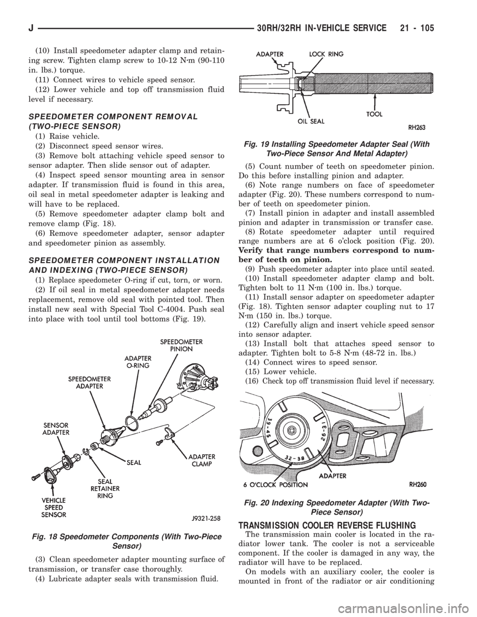
remove clamp (Fig. 18).
(6) Remove speedometer adapter, sensor adapter
and speedometer pinion as assembly.
SPEEDOMETER COMPONENT INSTALLATION
AND INDEXING (TWO-PIECE SENSOR)
(1) Replace speedometer O-ring if cut, torn, or worn.
(2) If oil seal in metal speedometer adapter needs
replacement, remove old seal with pointed tool. Then
install new seal with Special Tool C-4004. Push seal
into place with tool until tool bottoms (Fig. 19).
(3) Clean speedometer adapter mounting surface of
transmission, or transfer case thoroughly.
(4) Lubricate adapter seals with transmission fluid.
(5) Count number of teeth on speedometer pinion.
Do this before installing pinion and adapter.
(6) Note range numbers on face of speedometer
adapter (Fig. 20). These numbers correspond to num-
ber of teeth on speedometer pinion.
(7) Install pinion in adapter and install assembled
pinion and adapter in transmission or transfer case.
(8) Rotate speedometer adapter until required
range numbers are at 6 o'clock position (Fig. 20).
Verify that range numbers correspond to num-
ber of teeth on pinion.
(9) Push speedometer adapter into place until seated.
(10) Install speedometer adapter clamp and bolt.
Tighten bolt to 11 Nzm (100 in. lbs.) torque.
(11) Install sensor adapter on speedometer adapter
(Fig. 18). Tighten sensor adapter coupling nut to 17
Nzm (150 in. lbs.) torque.
(12) Carefully align and insert vehicle speed sensor
into sensor adapter.
(13) Install bolt that attaches speed sensor to
adapter. Tighten bolt to 5-8 Nzm (48-72 in. lbs.)
(14) Connect wires to speed sensor.
(15) Lower vehicle.
(16) Check top off transmission fluid level if necessary.
TRANSMISSION COOLER REVERSE FLUSHING
The transmission main cooler is located in the ra-
diator lower tank. The cooler is not a serviceable
component. If the cooler is damaged in any way, the
radiator will have to be replaced.
On models with an auxiliary cooler, the cooler is
mounted in front of the radiator or air conditioningFig. 18 Speedometer Components (With Two-Piece
Sensor)
Fig. 19 Installing Speedometer Adapter Seal (With
Two-Piece Sensor And Metal Adapter)
Fig. 20 Indexing Speedometer Adapter (With Two-
Piece Sensor)
J30RH/32RH IN-VEHICLE SERVICE 21 - 105
Page 1230 of 1784
low-reverse drum under any circumstances. Re-
place the drum and race as an assembly if either
component is damaged.
Examine the rear support carefully for wear,
cracks, scoring or other damage. Be sure the support
hub is a snug fit in the case and drum. Replace the
support if worn or damaged.
ASSEMBLING OVERRUNNING CLUTCH/LOW-
REVERSE DRUM
(1) Assemble clutch rollers and springs in retainer
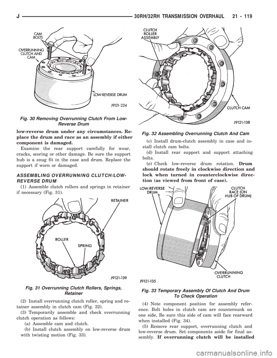
if necessary (Fig. 31).
(2) Install overrunning clutch roller, spring and re-
tainer assembly in clutch cam (Fig. 32).
(3) Temporarily assemble and check overrunning
clutch operation as follows:
(a) Assemble cam and clutch.
(b) Install clutch assembly on low-reverse drum
with twisting motion (Fig. 33).(c) Install drum-clutch assembly in case and in-
stall clutch cam bolts.
(d) Install rear support and support attaching
bolts.
(e) Check low-reverse drum rotation.Drum
should rotate freely in clockwise direction and
lock when turned in counterclockwise direc-
tion (as viewed from front of case).
(4) Note component position for assembly refer-
ence. Bolt holes in clutch cam are countersunk on
one side, Be sure this side of cam will face rearward
when installed (Fig. 34).
(5) Remove rear support, overrunning clutch and
low-reverse drum. Set components aside for final as-
sembly.If overrunning clutch will be installed
Fig. 30 Removing Overrunning Clutch From Low-
Reverse Drum
Fig. 31 Overrunning Clutch Rollers, Springs,
Retainer
Fig. 32 Assembling Overrunning Clutch And Cam
Fig. 33 Temporary Assembly Of Clutch And Drum
To Check Operation
J30RH/32RH TRANSMISSION OVERHAUL 21 - 119
Page 1257 of 1784
rect sequence. The correct sequence is line pressure
adjustment first and throttle pressure adjustment
last.
Line Pressure Adjustment
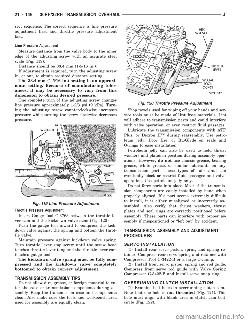
Measure distance from the valve body to the inner
edge of the adjusting screw with an accurate steel
scale (Fig. 119).
Distance should be 33.4 mm (1-5/16 in.).
If adjustment is required, turn the adjusting screw
in, or out, to obtain required distance setting.
The 33.4 mm (1-5/16 in.) setting is an approxi-
mate setting. Because of manufacturing toler-
ances, it may be necessary to vary from this
dimension to obtain desired pressure.
One complete turn of the adjusting screw changes
line pressure approximately 1-2/3 psi (9 kPa). Turn-
ing the adjusting screw counterclockwise increases
pressure while turning the screw clockwise decreases
pressure.
Throttle Pressure Adjustment
Insert Gauge Tool C-3763 between the throttle le-
ver cam and the kickdown valve stem (Fig. 120).
Push the gauge tool inward to compress the kick-
down valve against the spring and bottom the throt-
tle valve.
Maintain pressure against kickdown valve spring.
Turn throttle lever stop screw until the screw head
touches throttle lever tang and the throttle lever cam
touches gauge tool.
The kickdown valve spring must be fully com-
pressed and the kickdown valve completely
bottomed to obtain correct adjustment.
TRANSMISSION ASSEMBLY TIPS
Do not allow dirt, grease, or foreign material to en-
ter the case or transmission components during as-
sembly. Keep the transmission case and components
clean. Also make sure the tools and workbench area
used for assembly are equally clean.Shop towels used for wiping off your hands and ser-
vice tools must be made oflint freematerials. Lint
will adhere to transmission parts and could interfere
with valve operation, or even restrict fluid passages.
Lubricate the transmission components with ATF
Plus, or Dexron IIŸ during reassembly. Use petro-
leum jelly, Door Eze, or Ru-Glyde on seals and
O-rings to ease installation.
Petroleum jelly can also be used to hold thrust
washers and plates in position during assembly oper-
ations. However,do notuse chassis grease, bearing
grease, white grease, or similar lubricants on any
transmission part. These types of lubricants can
eventually block or restrict fluid passages and valve
operation. Use petroleum jelly only.
Do not force parts into place. Most of the transmis-
sion components are easily installed by hand when
properly aligned. If a part seems extremely difficult
to install, it is either misaligned or incorrectly as-
sembled. Also verify that thrust washers, thrust
plates and seal rings are correctly positioned before
assembly. These parts can interfere with proper as-
sembly if mispositioned or ``left out'' by accident.
TRANSMISSION ASSEMBLY AND ADJUSTMENT
PROCEDURES
SERVO INSTALLATION
(1) Install rear servo piston, spring and spring re-
tainer. Compress rear servo spring and retainer with
Compressor Tool C-3422-B or a large C-clamp.
(2) Install front servo piston, spring and rod guide.
Compress front servo rod guide with Valve Spring
Compressor C-3422-B and install servo snap ring.
OVERRUNNING CLUTCH INSTALLATION
(1) Examine bolt holes in overrunning clutch cam.
Note that one hole isnot threaded(Fig. 121). This
hole must align with blank area in clutch cam bolt
circle (Fig. 122).
Fig. 120 Throttle Pressure Adjustment
Fig. 119 Line Pressure Adjustment
21 - 146 30RH/32RH TRANSMISSION OVERHAULJ
Page 1258 of 1784
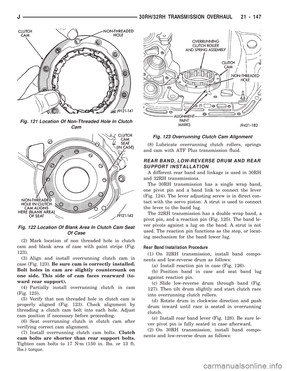
(2) Mark location of non threaded hole in clutch
cam and blank area of case with paint stripe (Fig.
123).
(3) Align and install overrunning clutch cam in
case (Fig. 123).Be sure cam is correctly installed.
Bolt holes in cam are slightly countersunk on
one side. This side of cam faces rearward (to-
ward rear support).
(4) Partially install overrunning clutch in cam
(Fig. 123).
(5) Verify that non threaded hole in clutch cam is
properly aligned (Fig. 123). Check alignment by
threading a clutch cam bolt into each hole. Adjust
cam position if necessary before proceeding.
(6) Seat overrunning clutch in clutch cam after
verifying correct cam alignment.
(7) Install overrunning clutch cam bolts.Clutch
cam bolts are shorter than rear support bolts.
Tighten cam bolts to 17 Nzm (150 in. lbs. or 13 ft.
lbs.) torque.(8) Lubricate overrunning clutch rollers, springs
and cam with ATF Plus transmission fluid.
REAR BAND, LOW-REVERSE DRUM AND REAR
SUPPORT INSTALLATION
A different rear band and linkage is used in 30RH
and 32RH transmissions.
The 30RH transmission has a single wrap band,
one pivot pin and a band link to connect the lever
(Fig. 124). The lever adjusting screw is in direct con-
tact with the servo piston. A strut is used to connect
the lever to the band lug.
The 32RH transmission has a double wrap band, a
pivot pin, and a reaction pin (Fig. 125). The band le-
ver pivots against a lug on the band. A strut is not
used. The reaction pin functions as the stop, or locat-
ing mechanism for the band lower lug.
Rear Band Installation Procedure
(1) On 32RH transmission, install band compo-
nents and low-reverse drum as follows:
(a) Install reaction pin in case (Fig. 126).
(b) Position band in case and seat band lug
against reaction pin.
(c) Slide low-reverse drum through band (Fig.
127). Then tilt drum slightly and start clutch race
into overrunning clutch rollers.
(d) Rotate drum in clockwise direction and push
drum inward until race is seated in overrunning
clutch.
(e) Install rear band lever (Fig. 128). Be sure le-
ver pivot pin is fully seated in case afterward.
(2) On 30RH transmission, install band compo-
nents and low-reverse drum as follows:
Fig. 123 Overrunning Clutch Cam Alignment
Fig. 121 Location Of Non-Threaded Hole In Clutch
Cam
Fig. 122 Location Of Blank Area In Clutch Cam Seat
Of Case
J30RH/32RH TRANSMISSION OVERHAUL 21 - 147