Page 1259 of 1784
(a) Assemble band and link. Be sure that notch
in one side of link is facing band (Fig. 129).
(b) Position band and link in case (Fig. 130).
(c) Slide low-reverse drum through band (Fig.131). Then tilt drum slightly and start clutch race
into overrunning clutch rollers.
(d) Rotate drum in clockwise direction and push
drum inward until race is seated in overrunning
clutch.
(e) Install rear band lever and pivot pin. Be sure
lever pivot pin is fully seated in case afterward.
(3) Hold low-reverse drum in position and install
rear support (Fig. 132)
(4) Align support with punch marks made during
disassembly.
(5) Install and tighten rear support bolts to 17 Nzm
(150 in. lbs.) torque.
Fig. 124 Rear Band Components (30RH)
Fig. 125 Rear Band Components (32RH)
Fig. 126 Rear Band Reaction Pin Installation (32RH)
Fig. 127 Rear Band And Low-Reverse Drum
Installation (32RH)
Fig. 128 Rear Band Lever And Pivot Pin Installation
(32RH)
21 - 148 30RH/32RH TRANSMISSION OVERHAULJ
Page 1300 of 1784

AW-4 TRANSMISSION REMOVAL AND INSTALLATION
INDEX
page page
Oil Pump Seal Replacement............... 189
Torque Converter Stator Clutch Inspection..... 189Transmission and Torque Converter Installation . 190
Transmission and Torque Converter Removal . . 189
TRANSMISSION AND TORQUE CONVERTER
REMOVAL
(1) Raise vehicle.
(2) Drain transmission fluid and reinstall oil pan
drain plug.
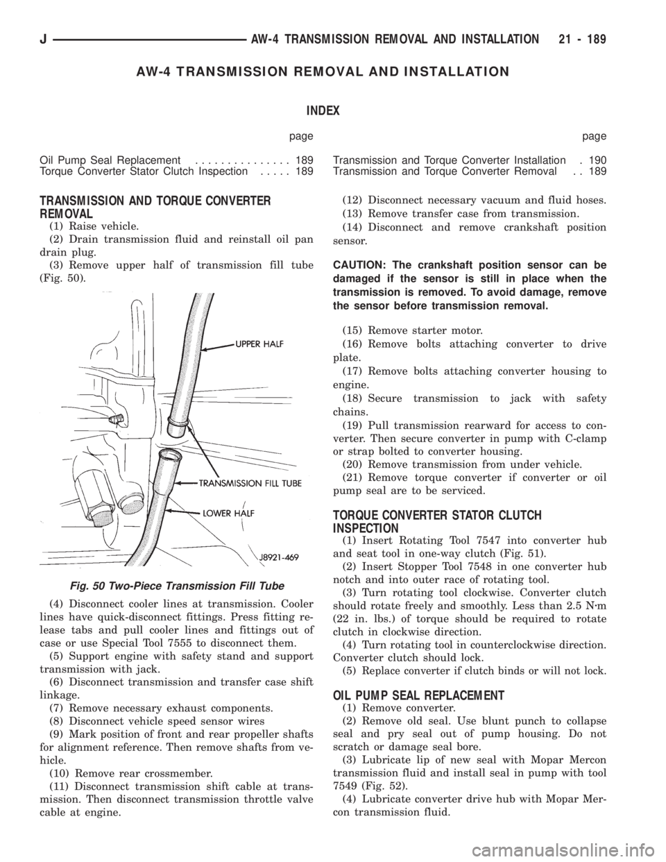
(3) Remove upper half of transmission fill tube
(Fig. 50).
(4) Disconnect cooler lines at transmission. Cooler
lines have quick-disconnect fittings. Press fitting re-
lease tabs and pull cooler lines and fittings out of
case or use Special Tool 7555 to disconnect them.
(5) Support engine with safety stand and support
transmission with jack.
(6) Disconnect transmission and transfer case shift
linkage.
(7) Remove necessary exhaust components.
(8) Disconnect vehicle speed sensor wires
(9) Mark position of front and rear propeller shafts
for alignment reference. Then remove shafts from ve-
hicle.
(10) Remove rear crossmember.
(11) Disconnect transmission shift cable at trans-
mission. Then disconnect transmission throttle valve
cable at engine.(12) Disconnect necessary vacuum and fluid hoses.
(13) Remove transfer case from transmission.
(14) Disconnect and remove crankshaft position
sensor.
CAUTION: The crankshaft position sensor can be
damaged if the sensor is still in place when the
transmission is removed. To avoid damage, remove
the sensor before transmission removal.
(15) Remove starter motor.
(16) Remove bolts attaching converter to drive
plate.
(17) Remove bolts attaching converter housing to
engine.
(18) Secure transmission to jack with safety
chains.
(19) Pull transmission rearward for access to con-
verter. Then secure converter in pump with C-clamp
or strap bolted to converter housing.
(20) Remove transmission from under vehicle.
(21) Remove torque converter if converter or oil
pump seal are to be serviced.
TORQUE CONVERTER STATOR CLUTCH
INSPECTION
(1) Insert Rotating Tool 7547 into converter hub
and seat tool in one-way clutch (Fig. 51).
(2) Insert Stopper Tool 7548 in one converter hub
notch and into outer race of rotating tool.
(3) Turn rotating tool clockwise. Converter clutch
should rotate freely and smoothly. Less than 2.5 Nzm
(22 in. lbs.) of torque should be required to rotate
clutch in clockwise direction.
(4) Turn rotating tool in counterclockwise direction.
Converter clutch should lock.
(5)
Replace converter if clutch binds or will not lock.
OIL PUMP SEAL REPLACEMENT
(1) Remove converter.
(2) Remove old seal. Use blunt punch to collapse
seal and pry seal out of pump housing. Do not
scratch or damage seal bore.
(3) Lubricate lip of new seal with Mopar Mercon
transmission fluid and install seal in pump with tool
7549 (Fig. 52).
(4) Lubricate converter drive hub with Mopar Mer-
con transmission fluid.
Fig. 50 Two-Piece Transmission Fill Tube
JAW-4 TRANSMISSION REMOVAL AND INSTALLATION 21 - 189
Page 1319 of 1784
(9) Remove old pump seal. Install new seal with
Seal Installer 7549 (Fig. 4).
(10) Lubricate and install gears in pump body.
(11) Assemble stator shaft and pump body. Tighten
shaft-to-body bolts to 10 Nzm (7 ft. lbs.) torque.
(12) Install new O-ring on pump body and new
seal rings on stator shaft.
(13) Install pump in torque converter and check
pump gear rotation. Gears must rotate smoothly
when turned clockwise and counterclockwise.
(14) Lubricate pump O-ring and seal rings with pe-
troleum jelly.
Fig. 5 Checking Pump Gear Rotation
Fig. 4 Installing Pump Seal
21 - 208 AW-4 TRANSMISSION OVERHAULJ
Page 1320 of 1784
OVERDRIVE PLANETARY GEAR AND CLUTCH
OVERHAUL
GEAR AND CLUTCH DISASSEMBLY
(1) Check operation of one-way clutch in clutch
drum. Hold drum and turn planetary shaft clockwise
and counterclockwise. Shaft should turn clockwise
freely but lock when turned counterclockwise. Re-
place one-way clutch if necessary.
(2) Remove overdrive clutch from planetary gear
(Fig. 3).
(3) Remove thrust bearing and race assembly from
clutch drum (Fig. 4).
Fig. 1 Overdrive Planetary Gear And Clutch Components
JAW-4 TRANSMISSION OVERHAUL 21 - 209
Page 1327 of 1784
mm (1.976 in.). Inside diameter is 28.9 mm (1.138 in.).
(16) Install clutch on planetary gear.
(17) Verify one-way clutch operation. Hold drum
and turn planetary shaft clockwise and counterclock-wise. Shaft should turn clockwise freely but lock
when turned counterclockwise.
OVERDRIVE SUPPORT OVERHAUL
SUPPORT DISASSEMBLY
(1) Check brake piston operation. Mount support
on clutch (Fig. 2).
(2) Apply compressed air through support feed hole
and observe brake piston movement (Fig. 2). Piston
Fig. 1 Overdrive Support Components
Fig. 26 Installing Retainer And Snap Ring
Fig. 27 Installing Clutch Drum Bearing And Race
Assembly
21 - 216 AW-4 TRANSMISSION OVERHAULJ
Page 1340 of 1784
(4) Turn planetary over and install race thrust
race (Fig. 3).
(5) Install front race and bearing and forward race
in ring gear (Fig. 4).
(6) Set planetary gear assembly aside for final as-
sembly.
SUN GEAR AND NO. 1 ONE-WAY CLUTCH
OVERHAUL
SUN GEAR AND CLUTCH DISASSEMBLY
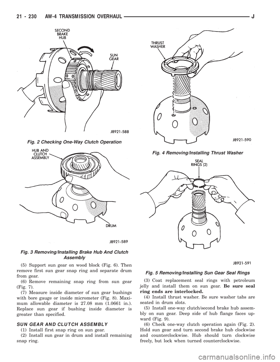
(1) Hold sun gear and turn second brake hub
clockwise and counterclockwise (Fig. 2). Hub should
rotate freely clockwise but lock when turned counter-clockwise. Replace one-way clutch and hub if they do
not operate properly.
(2) Remove one-way clutch/second brake hub as-
sembly from drum (Fig. 3).
(3) Remove thrust washer from drum (Fig. 4).
(4) Remove two seal rings from sun gear (Fig. 5).
Fig. 1 Sun Gear And One-Way Clutch Components
Fig. 3 Installing Front Planetary Thrust Race
Fig. 4 Installing Front Planetary Front Bearing And
Races
JAW-4 TRANSMISSION OVERHAUL 21 - 229
Page 1341 of 1784

(5) Support sun gear on wood block (Fig. 6). Then
remove first sun gear snap ring and separate drum
from gear.
(6) Remove remaining snap ring from sun gear
(Fig. 7).
(7) Measure inside diameter of sun gear bushings
with bore gauge or inside micrometer (Fig. 8). Maxi-
mum allowable diameter is 27.08 mm (1.0661 in.).
Replace sun gear if bushing inside diameter is
greater than specified.
SUN GEAR AND CLUTCH ASSEMBLY
(1) Install first snap ring on sun gear.
(2) Install sun gear in drum and install remaining
snap ring.(3) Coat replacement seal rings with petroleum
jelly and install them on sun gear.Be sure seal
ring ends are interlocked.
(4) Install thrust washer. Be sure washer tabs are
seated in drum slots.
(5) Install one-way clutch/second brake hub assem-
bly on sun gear. Deep side of hub flange faces up-
ward (Fig. 9).
(6) Check one-way clutch operation again (Fig. 2).
Hold sun gear and turn second brake hub clockwise
and counterclockwise. Hub should turn clockwise
freely, but lock when turned counterclockwise.
Fig. 2 Checking One-Way Clutch Operation
Fig. 3 Removing/Installing Brake Hub And Clutch
Assembly
Fig. 4 Removing/Installing Thrust Washer
Fig. 5 Removing/Installing Sun Gear Seal Rings
21 - 230 AW-4 TRANSMISSION OVERHAULJ
Page 1345 of 1784
REAR PLANETARY, NO. 2 ONE-WAY CLUTCH AND
OUTPUT SHAFT OVERHAUL
PLANETARY/BRAKE PACK/OUTPUT SHAFT
DISASSEMBLY
(1) Remove output shaft from gear assembly (Fig.
2).
(2) Remove and discard shaft seal ring (Fig. 4).
(3) Remove brake pack from planetary gear (Fig.
4).
(4) Measure thickness of each brake pack disc.
Minimum thickness is 1.51 mm (0.0594 in.). Replace
all discs if any disc is thinner than specified.
(5) Remove planetary gear from ring gear (Fig. 5).
(6) Check No. 2 one-way clutch. Hold planetary
gear and turn clutch inner race in both directions.Race should turn freely counterclockwise, but lock
when turned clockwise. Replace one-way clutch if
necessary.
Fig. 1 Rear Planetary, Brake Pack, Clutch And Output Shaft Components
Fig. 2 Removing/Installing Output Shaft
21 - 234 AW-4 TRANSMISSION OVERHAULJ