Page 1390 of 1784
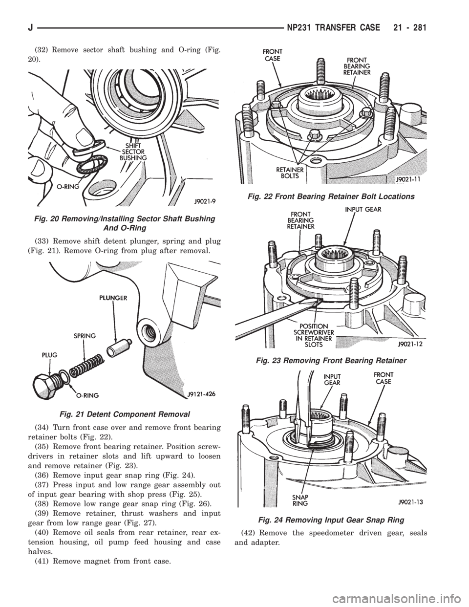
(22) Remove mainshaft, mode fork and shift rail as
assembly (Fig. 11).(23) Remove mode fork and shift rail from synchro
sleeve (Fig. 12).
(24) Remove synchro hub snap ring (Fig. 13).
Fig. 9 Mode Spring Removal
Fig. 10 Front Output Shaft And Drive Chain
Removal
Fig. 11 Removing Mainshaft, Mode Fork And Shift
Rail
Fig. 12 Removing Mode Fork From Sleeve
Fig. 13 Synchro Hub Snap Ring Removal/Installation
JNP231 TRANSFER CASE 21 - 279
Page 1391 of 1784
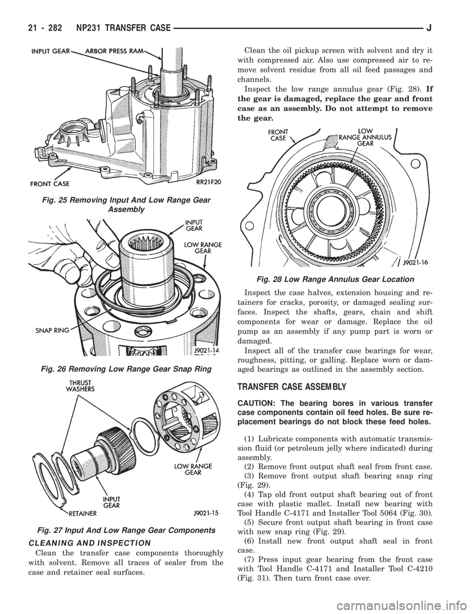
(25) Remove synchro sleeve, hub and struts (Fig. 14).
(26) Remove synchro hub and stop ring (Fig. 15).
(27) Remove drive sprocket (Fig. 16).
(28) Slide range fork pin out of shift sector (Fig. 17).
(29) Remove range fork and shift hub (Fig. 18).(30) Remove range lever from sector shaft.
(31) Remove shift sector (Fig. 19).
Fig. 14 Removing Synchro Sleeve, Hub And Struts
Fig. 15 Removing Synchro Hub And Stop Ring
Fig. 16 Drive Sprocket Removal/InstallationFig. 19 Shift Sector Removal/Installation
Fig. 17 Disengaging Range Fork
Fig. 18 Range Fork And Hub Removal/Installation
21 - 280 NP231 TRANSFER CASEJ
Page 1392 of 1784

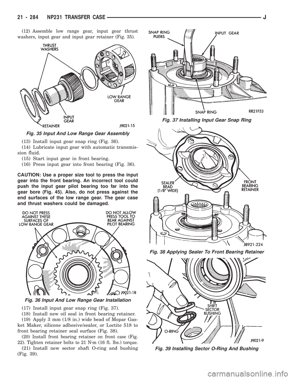
(32) Remove sector shaft bushing and O-ring (Fig.
20).
(33) Remove shift detent plunger, spring and plug
(Fig. 21). Remove O-ring from plug after removal.
(34) Turn front case over and remove front bearing
retainer bolts (Fig. 22).
(35) Remove front bearing retainer. Position screw-
drivers in retainer slots and lift upward to loosen
and remove retainer (Fig. 23).
(36) Remove input gear snap ring (Fig. 24).
(37) Press input and low range gear assembly out
of input gear bearing with shop press (Fig. 25).
(38) Remove low range gear snap ring (Fig. 26).
(39) Remove retainer, thrust washers and input
gear from low range gear (Fig. 27).
(40) Remove oil seals from rear retainer, rear ex-
tension housing, oil pump feed housing and case
halves.
(41) Remove magnet from front case.(42) Remove the speedometer driven gear, seals
and adapter.
Fig. 20 Removing/Installing Sector Shaft Bushing
And O-Ring
Fig. 21 Detent Component Removal
Fig. 22 Front Bearing Retainer Bolt Locations
Fig. 23 Removing Front Bearing Retainer
Fig. 24 Removing Input Gear Snap Ring
JNP231 TRANSFER CASE 21 - 281
Page 1393 of 1784

CLEANING AND INSPECTION
Clean the transfer case components thoroughly
with solvent. Remove all traces of sealer from the
case and retainer seal surfaces.Clean the oil pickup screen with solvent and dry it
with compressed air. Also use compressed air to re-
move solvent residue from all oil feed passages and
channels.
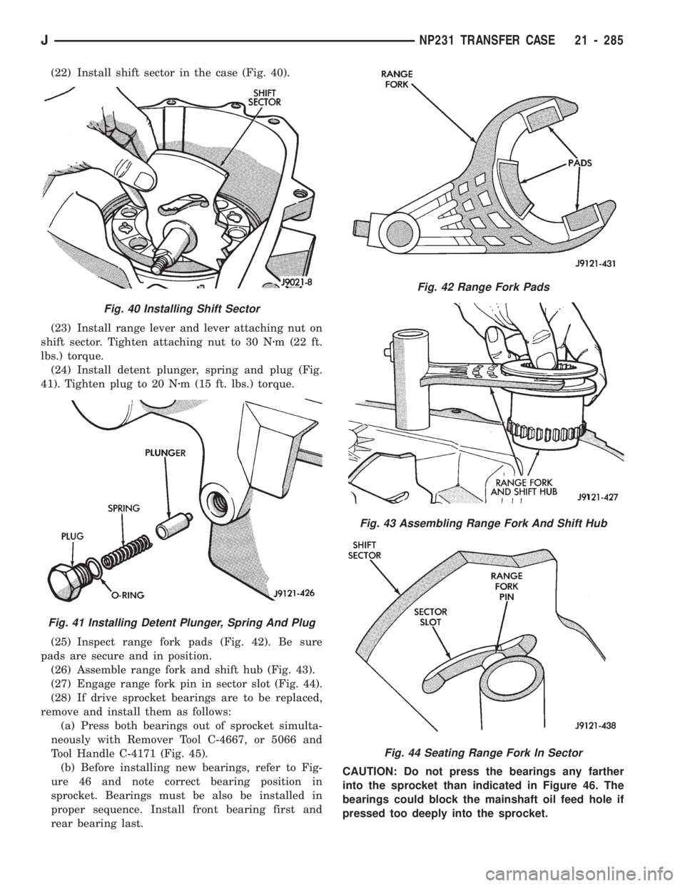
Inspect the low range annulus gear (Fig. 28).If
the gear is damaged, replace the gear and front
case as an assembly. Do not attempt to remove
the gear.
Inspect the case halves, extension housing and re-
tainers for cracks, porosity, or damaged sealing sur-
faces. Inspect the shafts, gears, chain and shift
components for wear or damage. Replace the oil
pump as an assembly if any pump part is worn or
damaged.
Inspect all of the transfer case bearings for wear,
roughness, pitting, or galling. Replace worn or dam-
aged bearings as outlined in the assembly section.
TRANSFER CASE ASSEMBLY
CAUTION: The bearing bores in various transfer
case components contain oil feed holes. Be sure re-
placement bearings do not block these feed holes.
(1) Lubricate components with automatic transmis-
sion fluid (or petroleum jelly where indicated) during
assembly.
(2) Remove front output shaft seal from front case.
(3) Remove front output shaft bearing snap ring
(Fig. 29).
(4) Tap old front output shaft bearing out of front
case with plastic mallet. Install new bearing with
Tool Handle C-4171 and Installer Tool 5064 (Fig. 30).
(5) Secure front output shaft bearing in front case
with new snap ring (Fig. 29).
(6) Install new front output shaft seal in front
case.
(7) Press input gear bearing from the front case
with Tool Handle C-4171 and Installer Tool C-4210
(Fig. 31). Then turn front case over.
Fig. 25 Removing Input And Low Range Gear
Assembly
Fig. 26 Removing Low Range Gear Snap Ring
Fig. 27 Input And Low Range Gear Components
Fig. 28 Low Range Annulus Gear Location
21 - 282 NP231 TRANSFER CASEJ
Page 1394 of 1784
(8) Install snap ring on new input gear bearing
and start bearing in case.
(9) Carefully press input gear bearing into case un-
til bearing snap ring seats against case (Fig. 32).
(10) Remove mainshaft pilot bearing from input
gear with Tool MD-998346 and two suitable size open
end wrenches (Fig. 33).(11) Install new pilot bearing in input gear with
shop press, Tool Handle C-4171 and Installer 5065
(Fig. 34).
Fig. 29 Removing/Installing Front Output Shaft
Bearing Snap Ring
Fig. 30 Installing Output Shaft Front Bearing
Fig. 31 Removing Input Gear Bearing
Fig. 32 Input Gear Bearing Installation
Fig. 33 Removing Mainshaft Pilot Bearing From
Input Gear
Fig. 34 Installing Mainshaft Pilot Bearing In Input
Gear
JNP231 TRANSFER CASE 21 - 283
Page 1395 of 1784

(12) Assemble low range gear, input gear thrust
washers, input gear and input gear retainer (Fig. 35).
(13) Install input gear snap ring (Fig. 36).
(14) Lubricate input gear with automatic transmis-
sion fluid.
(15) Start input gear in front bearing.
(16) Press input gear into front bearing (Fig. 36).
CAUTION: Use a proper size tool to press the input
gear into the front bearing. An incorrect tool could
push the input gear pilot bearing too far into the
gear bore (Fig. 45). Also, do not press against the
end surfaces of the low range gear. The gear case
and thrust washers could be damaged.
(17) Install input gear snap ring (Fig. 37).
(18) Install new oil seal in front bearing retainer.
(19) Apply 3 mm (1/8 in.) wide bead of Mopar Gas-
ket Maker, silicone adhesive/sealer, or Loctite 518 to
front bearing retainer seal surface (Fig. 38).
(20) Install front bearing retainer on front case (Fig.
22). Tighten retainer bolts to 21 Nzm (16 ft. lbs.) torque.
(21) Install new sector shaft O-ring and bushing
(Fig. 39).
Fig. 37 Installing Input Gear Snap Ring
Fig. 38 Applying Sealer To Front Bearing Retainer
Fig. 39 Installing Sector O-Ring And Bushing
Fig. 35 Input And Low Range Gear Assembly
Fig. 36 Input And Low Range Gear Installation
21 - 284 NP231 TRANSFER CASEJ
Page 1396 of 1784

(22) Install shift sector in the case (Fig. 40).
(23) Install range lever and lever attaching nut on
shift sector. Tighten attaching nut to 30 Nzm (22 ft.
lbs.) torque.
(24) Install detent plunger, spring and plug (Fig.
41). Tighten plug to 20 Nzm (15 ft. lbs.) torque.
(25) Inspect range fork pads (Fig. 42). Be sure
pads are secure and in position.
(26) Assemble range fork and shift hub (Fig. 43).
(27) Engage range fork pin in sector slot (Fig. 44).
(28) If drive sprocket bearings are to be replaced,
remove and install them as follows:
(a) Press both bearings out of sprocket simulta-
neously with Remover Tool C-4667, or 5066 and
Tool Handle C-4171 (Fig. 45).
(b) Before installing new bearings, refer to Fig-
ure 46 and note correct bearing position in
sprocket. Bearings must be also be installed in
proper sequence. Install front bearing first and
rear bearing last.CAUTION: Do not press the bearings any farther
into the sprocket than indicated in Figure 46. The
bearings could block the mainshaft oil feed hole if
pressed too deeply into the sprocket.
Fig. 42 Range Fork Pads
Fig. 43 Assembling Range Fork And Shift Hub
Fig. 44 Seating Range Fork In Sector
Fig. 40 Installing Shift Sector
Fig. 41 Installing Detent Plunger, Spring And Plug
JNP231 TRANSFER CASE 21 - 285
Page 1397 of 1784
(c) Install newfrontbearing first. Press bearing
flush with edge of sprocket bore (Fig. 47).
(d) Install newrearbearing (Fig. 48). Press
bearing in until 4.6 mm (3/16 in.) below edge of
bore as shown in Figure 46.
(29) Install spring and three struts in synchro hub
(Fig. 49).(30) Lubricate drive sprocket bearings, stop ring
and synchro hub with automatic transmission fluid.
(31) Install sprocket, stop ring and synchro hub on
mainshaft (Fig. 50).Be sure to seat hub struts on
stop ring lugs.
Fig. 45 Removing Drive Sprocket Bearings
Fig. 46 Correct Position Of Bearings In Sprocket
Fig. 47 Installing Drive Sprocket Front Bearing
Fig. 48 Installing Drive Sprocket Rear Bearing
Fig. 49 Installing Synchro Hub Spring And Struts
21 - 286 NP231 TRANSFER CASEJ