1994 JEEP CHEROKEE Transfer case
[x] Cancel search: Transfer casePage 1219 of 1784
30RH/32RH TRANSMISSION REMOVAL AND INSTALLATION
INDEX
page page
ConverterÐPump SealÐDrive Plate Service . . . 109
Transmission and Converter Installation....... 109Transmission and Converter Removal........ 108
TRANSMISSION AND CONVERTER REMOVAL
(1) Remove fan shroud attaching bolts.
(2) Disconnect transmission fill tube at upper
bracket.
(3) Raise vehicle.
(4) Remove inspection cover from converter hous-
ing and remove skid plate for access, if necessary.
(5) Remove transmission fill tube and fill tube
O-ring.
(6) Remove starter motor.
(7) Mark propeller shafts and axle yokes for align-
ment reference.
(8) Disconnect propeller shafts at yokes. Secure
shafts to frame rails with wire.
(9) Disconnect exhaust pipes at exhaust manifolds,
if necessary.
(10) Drain transfer case lubricant.
(11) Disconnect vehicle speed sensor wires.
(12) Disconnect transfer case shift linkage.
(13) Disconnect gearshift linkage and throttle ca-
ble at transmission levers.
(14) Disconnect park/neutral position switch wires.
(15) Disconnect and remove crankshaft position
sensor. Retain sensor bolt for reinstallation.
CAUTION: The crankshaft position sensor can be
damaged during transmission removal (or installa-
tion) if the sensor is still bolted to the engine block.
To avoid damage, remove the sensor before remov-
ing the transmission.
(16) Remove converter housing access cover and
mark drive plate and converter for alignment refer-
ence.
(17) Remove bolts attaching converter to drive
plate.
(18) Support engine with support stand.
(19) Support transmission-transfer case assembly
with transmission jack. Secure transmission to jack
with safety chain.
(20) Remove bolts/nuts attaching cushion and
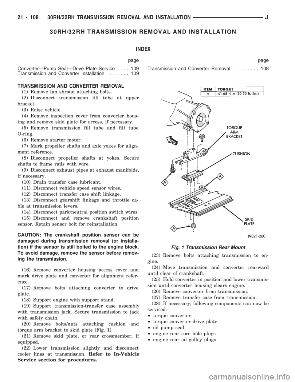
torque arm bracket to skid plate (Fig. 1).
(21) Remove skid plate, or rear crossmember, if
equipped.
(22) Lower transmission slightly and disconnect
cooler lines at transmission.Refer to In-Vehicle
Service section for procedures.(23) Remove bolts attaching transmission to en-
gine.
(24) Move transmission and converter rearward
until clear of crankshaft.
(25) Hold converter in position and lower transmis-
sion until converter housing clears engine.
(26) Remove converter from transmission.
(27) Remove transfer case from transmission.
(28) If necessary, following components can now be
serviced:
²torque converter
²torque converter drive plate
²oil pump seal
²engine rear core hole plugs
²engine rear oil galley plugs
Fig. 1 Transmission Rear Mount
21 - 108 30RH/32RH TRANSMISSION REMOVAL AND INSTALLATIONJ
Page 1222 of 1784
(b) Align and install new spacer on sensor
pickup face. Spacer has adhesive backing so it will
adhere to sensor face.
(c) Insert sensor into housing until it just
touches ring gear teeth. Then install and tighten
sensor attaching bolt. Correct clearance is estab-
lished when spacer is peeled off by ring gear dur-
ing engine startup.
(10) Install transmission fill tube and O-ring (Fig.
6).
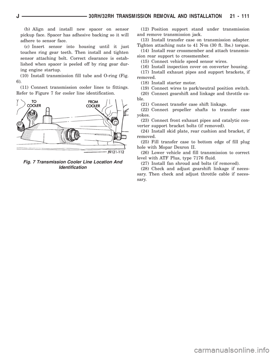
(11) Connect transmission cooler lines to fittings.
Refer to Figure 7 for cooler line identification.(12) Position support stand under transmission
and remove transmission jack.
(13) Install transfer case on transmission adapter.
Tighten attaching nuts to 41 Nzm (30 ft. lbs.) torque.
(14) Install rear crossmember and attach transmis-
sion rear support to crossmember.
(15) Connect vehicle speed sensor wires.
(16) Install inspection cover on converter housing.
(17) Install exhaust pipes and support brackets, if
removed.
(18) Install starter motor.
(19) Connect wires to park/neutral position switch.
(20) Connect gearshift and linkage and throttle ca-
ble.
(21) Connect transfer case shift linkage.
(22) Connect propeller shafts to transfer case
yokes.
(23) Connect front exhaust pipes and catalytic con-
verter support bracket bolts (if removed).
(24) Install skid plate, rear cushion and bracket, if
removed.
(25) Fill transfer case to bottom edge of fill plug
hole with Mopar Dexron II.
(26) Lower vehicle and fill transmission to correct
level with ATF Plus, type 7176 fluid.
(27) Install fan shroud and bolts (if removed).
(28) Check and adjust gearshift linkage if neces-
sary. Then check and adjust throttle cable if neces-
sary.
Fig. 7 Transmission Cooler Line Location And
Identification
J30RH/32RH TRANSMISSION REMOVAL AND INSTALLATION 21 - 111
Page 1267 of 1784
AW-4 AUTOMATIC TRANSMISSION
CONTENTS
page page
AW-4 IN-VEHICLE SERVICE............. 173
AW-4 TRANSMISSION DIAGNOSIS........ 167
AW-4 TRANSMISSION OVERHAUL........ 192
AW-4 TRANSMISSION REMOVAL AND
INSTALLATION....................... 189GENERAL INFORMATION................ 156
TRANSMISSION/TRANSFER CASE
SPECIFICATIONS..................... 320
GENERAL INFORMATION
INDEX
page page
Components and Operation................ 157
Description............................ 156
FirstÐThirdÐReverse Gear Components...... 159
Fourth Gear Overdrive Components......... 158
Geartrain Operation and Application Charts.... 159Hydraulic System........................ 160
Torque Converter........................ 158
Transmission Identification................. 157
Transmission Ranges and Shift Lever Positions . 157
DESCRIPTION
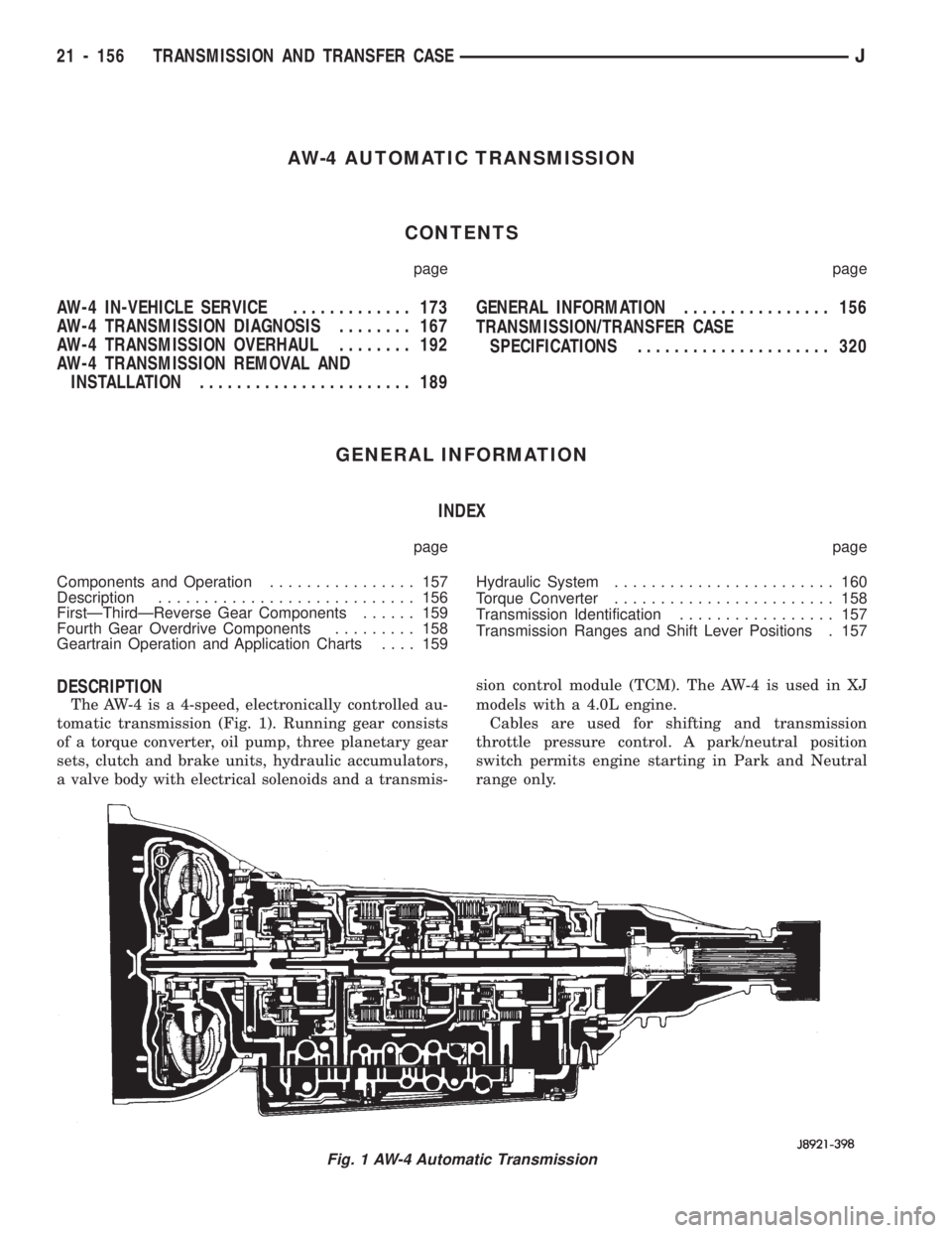
The AW-4 is a 4-speed, electronically controlled au-
tomatic transmission (Fig. 1). Running gear consists
of a torque converter, oil pump, three planetary gear
sets, clutch and brake units, hydraulic accumulators,
a valve body with electrical solenoids and a transmis-sion control module (TCM). The AW-4 is used in XJ
models with a 4.0L engine.
Cables are used for shifting and transmission
throttle pressure control. A park/neutral position
switch permits engine starting in Park and Neutral
range only.
Fig. 1 AW-4 Automatic Transmission
21 - 156 TRANSMISSION AND TRANSFER CASEJ
Page 1280 of 1784
PRESSURE TEST ANALYSIS
If pressures in D and Reverse are higher than
specified, check for the following:
²throttle cable loose, worn, binding or out of adjust-
ment
²throttle valve, downshift plug, throttle cam, or pri-
mary regulator valve are sticking, worn or damaged
If pressures in D and Reverse are lower than spec-
ified, check for following:
²throttle cable loose, worn, binding or out of adjust-
ment
²throttle valve, downshift plug, throttle cam stick-
ing, worn or damaged
²primary regulator valve sticking, worn, or dam-
aged
²oil pump gears or housing worn or damaged
²overdrive clutch worn or damaged
If pressures are low in D range only, check for fol-
lowing:
²forward clutch worn or damaged
²fluid leakage in D range circuit (component seal
and O-rings)
If pressures are low in Reverse only, check for fol-
lowing:
²shift cable and manual valve out of adjustment
²fluid leakage in reverse circuit (component seal
and O-rings)
²direct clutch worn or damaged
²first/reverse brake worn or damaged
TORQUE CONVERTER STALL TEST
Stall testing checks the holding ability of the trans-
mission clutches and brakes and of the torque con-
verter stator overrunning clutch.
(1) Be sure transmission fluid is at normal operat-
ing temperature.
(2) Connect tachometer to engine. Position tachom-
eter so it can be viewed from drivers seat.
(3) Apply parking brakes and block wheels.
(4) Apply and hold service brakes.
(5) Shift transfer case into 2H position. On models
with NP249 transfer case, leave transfer case in 4H
position.
(6) Start engine.
WARNING: DO NOT ALLOW ANYONE TO STAND AT
THE FRONT OR REAR OF THE VEHICLE DURING
THE TEST.
(7) Shift transmission into D range.
(8) Press accelerator pedal to wide open throttle
position and note maximum engine rpm. Stall speed
should be 2100 to 2400 rpm in D range.
CAUTION: Do not maintain wide open throttle for
more than 3-4 seconds at a time.(9) Release throttle and shift transmission into
Neutral. Allow transmission fluid to cool for 15-20
seconds.
(10) Shift transmission into Reverse.
(11) Press accelerator down to wide open throttle
position and note maximum engine rpm. Stall speed
should be 2100-to-2400 rpm in Reverse.
STALL SPEED TEST ANALYSIS
If engine rpm is lower than specified in D and Re-
verse, check for the following:
²engine output/performance insufficient
²stator overrunning clutch in torque converter not
holding if engine speed was 1500 rpm or less.
If stall speed in D range is higher than specified,
check for the following:
²line pressure low
²forward clutch slipping
²No. 2 one-way clutch not holding
²overdrive one-way clutch not holding
If stall speed in Reverse was higher than specified,
check for the following:
²line pressure low
²direct clutch slipping
²first/ reverse brake slipping
²overdrive one-way clutch not holding
If stall speeds were higher than specified in both D
and Reverse, check for the following:
²low fluid level
²line pressure low
²overdrive one-way clutch not holding
TIME LAG TEST
This test checks general condition of the overdrive
clutch, forward clutch, rear clutch and first/reverse
brake. Condition is indicated by the amount of time
required for clutch/brake engagement with the en-
gine at curb idle speed. Engagement time is mea-
sured for D and Reverse positions. A stop watch is
recommended for test accuracy.
TEST PROCEDURE
(1) Check and adjust transmission fluid level if
necessary.
(2) Bring transmission to normal operating tem-
perature.
(3) Apply parking brakes and turn off air condi-
tioning unit.
(4) Shift transfer case into 2H range. On models
with NP249 transfer case, leave transfer case in 4H
range.
(5) Start engine and check curb idle speed. Adjust
speed if necessary. Curb idle must be correct to en-
sure accurate test results.
(6) Shift transmission into Neutral and set stop
watch.
(7) During following test steps, start stop watch as
soon as shift lever reaches D and Reverse ranges.
JAW-4 TRANSMISSION DIAGNOSIS 21 - 169
Page 1293 of 1784
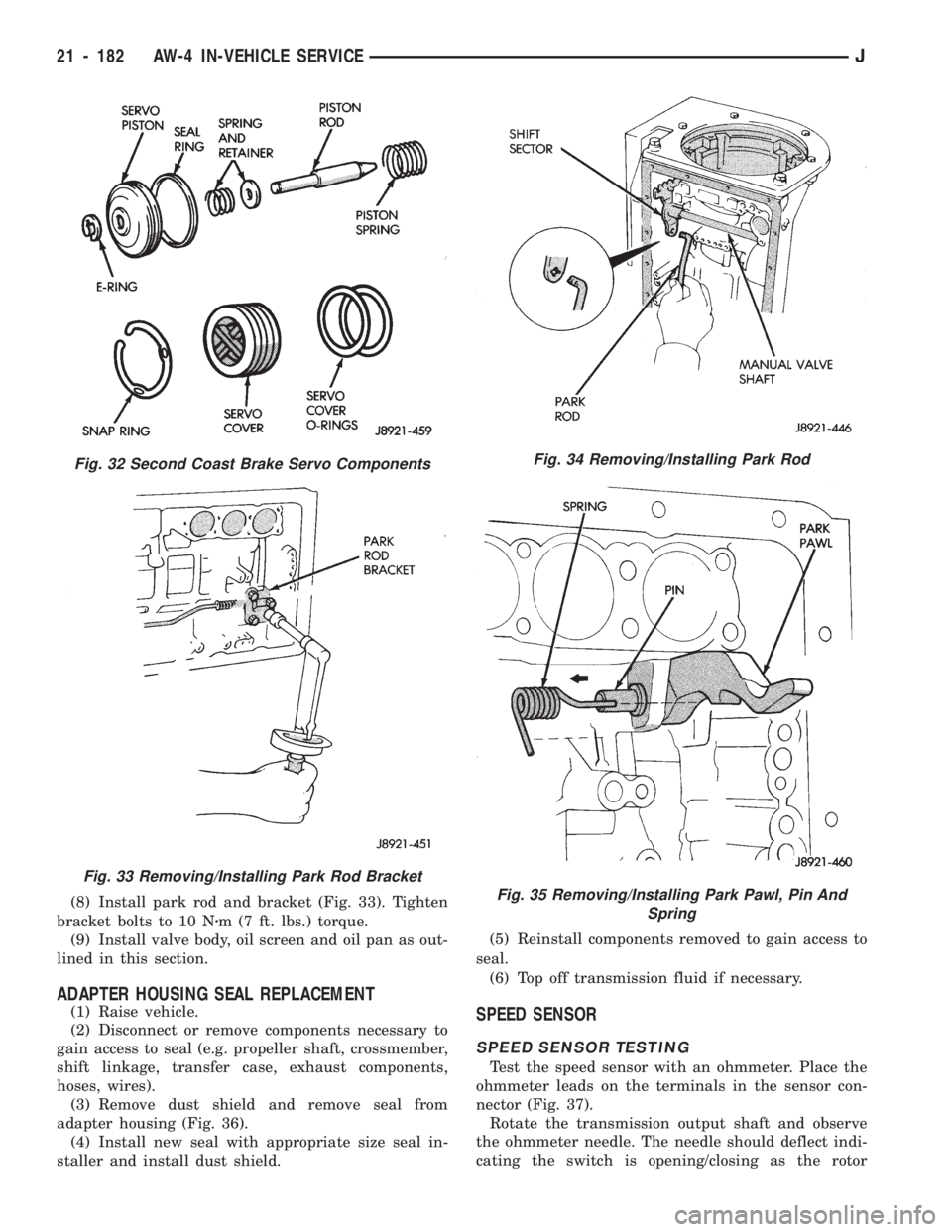
(8) Install park rod and bracket (Fig. 33). Tighten
bracket bolts to 10 Nzm (7 ft. lbs.) torque.
(9) Install valve body, oil screen and oil pan as out-
lined in this section.
ADAPTER HOUSING SEAL REPLACEMENT
(1) Raise vehicle.
(2) Disconnect or remove components necessary to
gain access to seal (e.g. propeller shaft, crossmember,
shift linkage, transfer case, exhaust components,
hoses, wires).
(3) Remove dust shield and remove seal from
adapter housing (Fig. 36).
(4) Install new seal with appropriate size seal in-
staller and install dust shield.(5) Reinstall components removed to gain access to
seal.
(6) Top off transmission fluid if necessary.SPEED SENSOR
SPEED SENSOR TESTING
Test the speed sensor with an ohmmeter. Place the
ohmmeter leads on the terminals in the sensor con-
nector (Fig. 37).
Rotate the transmission output shaft and observe
the ohmmeter needle. The needle should deflect indi-
cating the switch is opening/closing as the rotor
Fig. 34 Removing/Installing Park Rod
Fig. 35 Removing/Installing Park Pawl, Pin And
Spring
Fig. 32 Second Coast Brake Servo Components
Fig. 33 Removing/Installing Park Rod Bracket
21 - 182 AW-4 IN-VEHICLE SERVICEJ
Page 1294 of 1784
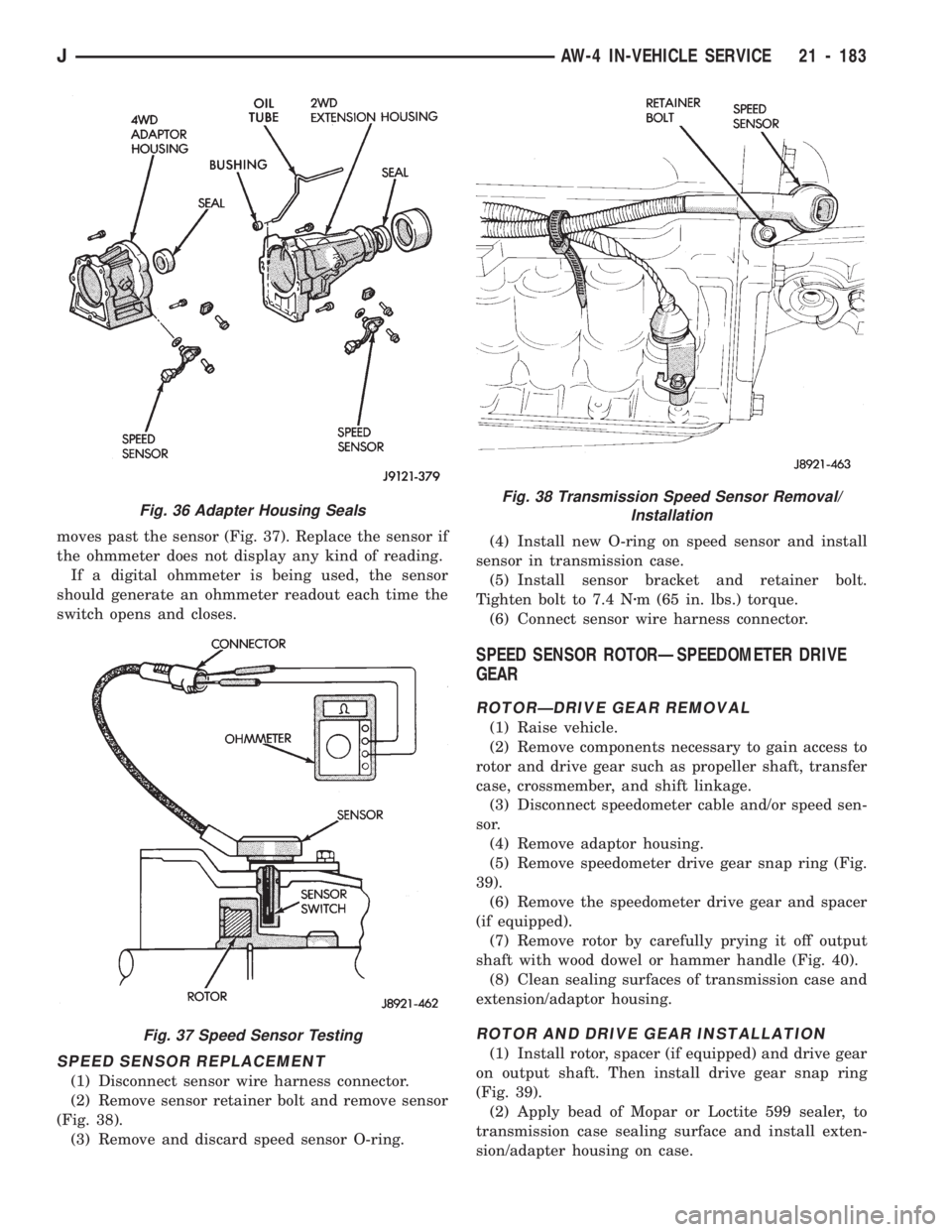
moves past the sensor (Fig. 37). Replace the sensor if
the ohmmeter does not display any kind of reading.
If a digital ohmmeter is being used, the sensor
should generate an ohmmeter readout each time the
switch opens and closes.
SPEED SENSOR REPLACEMENT
(1) Disconnect sensor wire harness connector.
(2) Remove sensor retainer bolt and remove sensor
(Fig. 38).
(3) Remove and discard speed sensor O-ring.(4) Install new O-ring on speed sensor and install
sensor in transmission case.
(5) Install sensor bracket and retainer bolt.
Tighten bolt to 7.4 Nzm (65 in. lbs.) torque.
(6) Connect sensor wire harness connector.
SPEED SENSOR ROTORÐSPEEDOMETER DRIVE
GEAR
ROTORÐDRIVE GEAR REMOVAL
(1) Raise vehicle.
(2) Remove components necessary to gain access to
rotor and drive gear such as propeller shaft, transfer
case, crossmember, and shift linkage.
(3) Disconnect speedometer cable and/or speed sen-
sor.
(4) Remove adaptor housing.
(5) Remove speedometer drive gear snap ring (Fig.
39).
(6) Remove the speedometer drive gear and spacer
(if equipped).
(7) Remove rotor by carefully prying it off output
shaft with wood dowel or hammer handle (Fig. 40).
(8) Clean sealing surfaces of transmission case and
extension/adaptor housing.
ROTOR AND DRIVE GEAR INSTALLATION
(1) Install rotor, spacer (if equipped) and drive gear
on output shaft. Then install drive gear snap ring
(Fig. 39).
(2) Apply bead of Mopar or Loctite 599 sealer, to
transmission case sealing surface and install exten-
sion/adapter housing on case.
Fig. 36 Adapter Housing Seals
Fig. 37 Speed Sensor Testing
Fig. 38 Transmission Speed Sensor Removal/
Installation
JAW-4 IN-VEHICLE SERVICE 21 - 183
Page 1300 of 1784
AW-4 TRANSMISSION REMOVAL AND INSTALLATION
INDEX
page page
Oil Pump Seal Replacement............... 189
Torque Converter Stator Clutch Inspection..... 189Transmission and Torque Converter Installation . 190
Transmission and Torque Converter Removal . . 189
TRANSMISSION AND TORQUE CONVERTER
REMOVAL
(1) Raise vehicle.
(2) Drain transmission fluid and reinstall oil pan
drain plug.
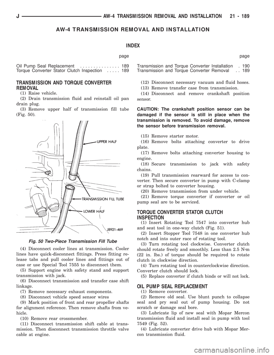
(3) Remove upper half of transmission fill tube
(Fig. 50).
(4) Disconnect cooler lines at transmission. Cooler
lines have quick-disconnect fittings. Press fitting re-
lease tabs and pull cooler lines and fittings out of
case or use Special Tool 7555 to disconnect them.
(5) Support engine with safety stand and support
transmission with jack.
(6) Disconnect transmission and transfer case shift
linkage.
(7) Remove necessary exhaust components.
(8) Disconnect vehicle speed sensor wires
(9) Mark position of front and rear propeller shafts
for alignment reference. Then remove shafts from ve-
hicle.
(10) Remove rear crossmember.
(11) Disconnect transmission shift cable at trans-
mission. Then disconnect transmission throttle valve
cable at engine.(12) Disconnect necessary vacuum and fluid hoses.
(13) Remove transfer case from transmission.
(14) Disconnect and remove crankshaft position
sensor.
CAUTION: The crankshaft position sensor can be
damaged if the sensor is still in place when the
transmission is removed. To avoid damage, remove
the sensor before transmission removal.
(15) Remove starter motor.
(16) Remove bolts attaching converter to drive
plate.
(17) Remove bolts attaching converter housing to
engine.
(18) Secure transmission to jack with safety
chains.
(19) Pull transmission rearward for access to con-
verter. Then secure converter in pump with C-clamp
or strap bolted to converter housing.
(20) Remove transmission from under vehicle.
(21) Remove torque converter if converter or oil
pump seal are to be serviced.
TORQUE CONVERTER STATOR CLUTCH
INSPECTION
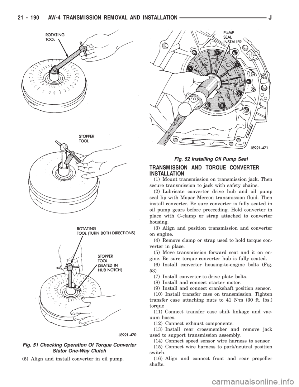
(1) Insert Rotating Tool 7547 into converter hub
and seat tool in one-way clutch (Fig. 51).
(2) Insert Stopper Tool 7548 in one converter hub
notch and into outer race of rotating tool.
(3) Turn rotating tool clockwise. Converter clutch
should rotate freely and smoothly. Less than 2.5 Nzm
(22 in. lbs.) of torque should be required to rotate
clutch in clockwise direction.
(4) Turn rotating tool in counterclockwise direction.
Converter clutch should lock.
(5)
Replace converter if clutch binds or will not lock.
OIL PUMP SEAL REPLACEMENT
(1) Remove converter.
(2) Remove old seal. Use blunt punch to collapse
seal and pry seal out of pump housing. Do not
scratch or damage seal bore.
(3) Lubricate lip of new seal with Mopar Mercon
transmission fluid and install seal in pump with tool
7549 (Fig. 52).
(4) Lubricate converter drive hub with Mopar Mer-
con transmission fluid.
Fig. 50 Two-Piece Transmission Fill Tube
JAW-4 TRANSMISSION REMOVAL AND INSTALLATION 21 - 189
Page 1301 of 1784
(5) Align and install converter in oil pump.
TRANSMISSION AND TORQUE CONVERTER
INSTALLATION
(1) Mount transmission on transmission jack. Then
secure transmission to jack with safety chains.
(2) Lubricate converter drive hub and oil pump
seal lip with Mopar Mercon transmission fluid. Then
install converter. Be sure converter is fully seated in
oil pump gears before proceeding. Hold converter in
place with C-clamp or strap attached to converter
housing.
(3) Align and position transmission and converter
on engine.
(4) Remove clamp or strap used to hold torque con-
verter in place.
(5) Move transmission forward seat and it on en-
gine. Be sure torque converter hub is fully seated.
(6)
Install converter housing-to-engine bolts (Fig.
53).
(7) Install converter-to-drive plate bolts.
(8) Install and connect starter motor.
(9) Install and connect crankshaft position sensor.
(10) Install transfer case on transmission. Tighten
transfer case attaching nuts to 41 Nzm (30 ft. lbs.)
torque
(11) Connect transfer case shift linkage and vac-
uum hoses.
(12) Connect exhaust components.
(13) Install rear crossmember and remove jack
used to support transmission assembly.
(14) Connect speed sensor wire harness to sensor.
(15) Connect wire harness to park/neutral position
switch.
(16) Align and connect front and rear propeller
shafts.
Fig. 51 Checking Operation Of Torque Converter
Stator One-Way Clutch
Fig. 52 Installing Oil Pump Seal
21 - 190 AW-4 TRANSMISSION REMOVAL AND INSTALLATIONJ