1994 JEEP CHEROKEE Transfer case
[x] Cancel search: Transfer casePage 349 of 1784
other side. When coolant temperature is too high the
switch closes providing a path to ground, and the indi-
cator bulb lights.
TACHOMETER
The tachometer displays the engine speed (RPM).
With the engine running, the tachometer receives an
engine speed signal from the Powertrain Control
Module pin 43 (values shown in Specifications chart).
SPEEDOMETER/ODOMETER SYSTEM
The speedometer/odometer system consists of an elec-
tric speedometer and pushbutton reset odometer
mounted in the cluster. The system also includes the
wire harness from the cluster to the vehicle speed sen-
sor at the transmission, and the adapter and pinion in
the transmission. A signal is sent from a transmission
mounted vehicle speed sensor to the speedometer/odom-
eter circuitry through the wiring harness. Refer to
Group 21 - Transmission for selecting the proper pinion,
and selecting and indexing the proper adapter.
FUEL GAUGE
The fuel gauge pointer position is controlled by a
magnetic field created by electrical current flow through
the coils within the gauge. A change in current flow will
change the magnetic field which changes the pointer po-
sition. The fuel level sender is a variable resistor that
changes electrical resistance with a change of the level
of fuel in the tank (values shown in Specifications
chart).
LOW FUEL WARNING LAMP
The low fuel warning lamp will light when the fuel
level falls below approximately 4 gallons. A low fuel
warning module controls when the lamp will light.
When the module senses 66.5 ohms or less from the
fuel level sender for 10 continuous seconds, the lamp
will light. The lamp will remain on until the module
senses 63.5 ohms or more from the fuel level sender
for 20 continuous seconds.
UPSHIFT INDICATOR LAMP
Vehicles equipped with manual transmissions have an
optional upshift indicator lamp. The lamp is controlled
by the Powertrain Control Module. The lamp lights to
indicate when the driver should shift to the next high-
est gear for best fuel economy. The Powertrain Control
Module will turn the lamp off after 3 to 5 seconds if the
upshift is not performed. The lamp will remain off until
the vehicle stops accelerating and is brought back to the
range of lamp operation or shifted into another gear.
The indicator lamp is normally illuminated when
the ignition switch is turned ON and is turned off
when the engine is started. The lamp will be lighted
during engine operation according to engine speed
and load.
BRAKE INDICATOR LAMP
The brake indicator lamp warns the driver that the
parking brake is applied or that hydraulic pressure in
the split brake system is unequal.
Voltage is supplied through the brake indicator
bulb to 3 switches. A path to ground for the current
is available if:
²The brake warning switch is closed (with unequal
brake system hydraulic pressures), or
²
The ignition switch is in the START position (to test
the bulb), or
²The park brake switch is closed (with the parking
brake applied).
ANTI-LOCK BRAKE SYSTEM (ABS) INDICATOR
LAMP
The anti-lock brake system (ABS) lamp lights to in-
dicate a system self-check is in process at vehicle
start-up. If light remains on after start-up or comes
on and stays on while driving, it may indicate that
the ABS system has detected a malfunction or has
become inoperative.
4WD INDICATOR LAMP
COMMAND-TRAC 4WD
The PART TIME lamp lights when the vehicle is en-
gaged in four-wheel drive mode. Voltage is supplied to
one side of the indicator bulb. A switch in the transfer
case area is connected to the other side of the indicator
bulb. When the switch is closed, a path to ground is pro-
vided and the indicator bulb lights.
SELECT-TRAC 4WD
The four-wheel drive icon or FULL TIME lamp
lights when the vehicle is engaged in full time four-
wheel drive mode. The PART TIME lamp lights when
the vehicle is in part time four-wheel drive mode.
Voltage is supplied to one side of the indicators.
Switches in the transfer case area are connected to
the other side of the indicator bulbs. When a switch
is closed, a path to ground is provided and the indi-
cator bulb lights.
MALFUNCTION INDICATOR LAMP (CHECK ENGINE)
The Malfunction Indicator Lamp (Check Engine)
lights each time the ignition switch is turned ON and
stays on for 3 seconds as a bulb test.
If the PCM receives an incorrect signal or no signal
from certain sensors or emission related systems the
lamp is turned on (pin 32 of PCM). This is a warning
that the PCM has recorded a system or sensor mal-
function. In some cases when a diagnostic trouble
code is declared the PCM will go into a limp-in mode
in an attempt to keep the system operating. It sig-
nals an immediate need for service.
The lamp also can be used to display diagnostic
trouble codes (DTC). Cycle the ignition switch ON,
OFF, ON, OFF, ON within 5 seconds. This will allow
any trouble codes stored in the PCM memory to be
displayed in a series of flashes representing digits.
8E - 2 XJ INSTRUMENT PANEL AND GAUGESJ
Page 644 of 1784
Wiring Diagram Name Sheet Number
Fuse #15...............................1,41
Fuse #17...........................2,10,55,74
Fuse #18...............................1,66
Fuse #19.............................1,41,47
Gauges
Engine Coolant Temperature Gauge...........59,60,61
Engine Oil Pressure Gauge.................59,60,61
Fuel Gauge...........................59,60,61
G Sensor..................................30
Generator.................................5,6
Glove Box Lamp.............................49
Hazard Flasher............................35,46
Headlamp Delay Module........................43
Headlamp Dimmer Switch.......................41
Headlamp Switch...........................41,42
Fog Lamp Illumination........................42
Fog Lamp Switch...........................42
Headlamp Dimmer Switch.....................41
Headlamp Switch...........................41
Headlamps...............................39,40
Heat Mode Select Switch.......................68
Heated Oxygen Sensor.......................13,21
Heated Rear Window..........................66
Relay...................................66
Grid...................................66
Switch..................................66
Heated Rear Window Switch Lamp.................47
Heater A/C Panel Lamp........................47
Heater and A/C System......................69,70
A/C Mode Selector Switch.....................70
A/C Compressor Clutch.......................69
A/C Compressor Clutch Relay...................69
A/C Heater Blower Motor......................70
A/C Thermostat............................69
A/C Low Pressure Switch.....................69
Blower Resistor............................70
Blower Switch.............................70
Powertrain Control Module.....................69
Heat Mode Select Switch.......................68
Heater Blower Motor..........................68
Heater,Engine Block...........................37
Heater System..............................68
Blower Resistor............................68
Blower Switch.............................68
Heater Blower Motor.........................68
Heater Mode Select Switch....................68
Heavy Duty Cooling 4.OL.......................23
Fan Control Relay...........................23
Powertrain Control Module.....................23
Radiator Fan Motor.........................23
High Beam Indicator Lamp..................59,60,61
High Beam Relay............................40
Hi-Line Instrument Cluster.......................61
Horn Brush/Slip Ring..........................34
Horn Relay................................34
Horn Switch................................34
Horns....................................34
Hydraulic Actuation Unit, ABS....................33Wiring Diagram Name Sheet Number
Idle Air Control Motor.......................15,22
Ignition Key Warning Switch.....................74
Ignition Switch..............................2,9
Ignition System............................9,10
Injectors................................15,22
In Line Circuit Breaker..........................2
Instrument Cluster............................55
Powertrain Control Module.....................55
Washer Fluid Level Switch.....................55
Instrument Cluster (Hi-Line)......................61
Instrument Cluster (Lo-Line).....................60
Instrument Cluster (Standard)....................59
Instrument Cluster Connector..................55,108
Instrument Cluster Printed Circuit Board (W/ABS).......57
Instrument Cluster Printed Circuit Board (W/O ABS)......58
Instrument Cluster Indicators.....................56
Instrument Panel Ground.......................62
Instrument Panel Illumination...................47,48
Ashtray Lamp.............................48
Cigar Lighter Lamp..........................48
Fog Lamp Illumination........................47
Heater A/C Panel Lamp.......................47
Heater Rear Window Switch Lamp................47
Rear Wiper Wash Switch Lamp..................47
Transfer Case Lamp.........................48
Transmission Range Switch Lamp................48
Intake Air Temperature Sensor..................14,19
Intermittent Front Wipers/Washers.................64
Intermittent Wiper Module.......................64
Lamps
ABS Green Indicator Lamp.....................57
ABS Red Indicator Lamp......................57
Ashtray Lamp.............................48
Cargo Lamp..............................50
Center High Mounted Stop Lamps................98
Cigar Lighter Lamp..........................48
Dome Lamp..............................51
Dome/Reading Lamp.........................51
Fog Lamp Illumination........................47
4WD Indicator Lamp.....................26,57,58
Full Time Indicator Lamp....................57,58
Glove Box Lamp...........................49
Heated Rear Window Switch Lamp...............47
Heater A/C Panel Lamp.......................47
High Beam Indicator Lamp.................59,60,61
Indicator Lamp 4WD.......................57,58
Instrument Cluster Illumination Lamps.........59,60,61
Left Back-Up Lamp........................91,93
Left Courtesy Lamp.........................49
Left Fog Lamp.............................39
Left Headlamp.............................39
Left Park/Turn Signal Lamp....................39
Left Side Marker Lamp (Front)..................39
Left Side Marker Lamp (Rear)................91,93
Left Tail/Stop Lamp.......................91,93
Left Turn Indicator Lamp..................59,60,61
Left Turn Lamp (Amber)....................91,93
Left Vanity Lamp...........................51
JWIRING DIAGRAMS 8W - 151
Page 645 of 1784
Wiring Diagram Name Sheet Number
License Lamp...........................91,95
Low Washer Indicator Lamp..................57,58
Malfunction Indicator Lamp..................57,58
Maintenance Required Indicator Lamp...........57,58
Park Brake Indicator Lamp.....................58
Reading Lamp.............................51
Rear Wiper/Wash Switch Lamp..................47
Right Back-Up Lamp.......................92,96
Right Courtesy Lamp........................49
Right Fog Lamp............................40
Right Headlamp............................40
Right Park/Turn Signal Lamp...................40
Right Side Marker Lamp (Front).................40
Right Side Marker (Rear)....................92,96
Right Tail/Stop Lamp......................92,96
Right Turn Indicator Lamp.................59,60,61
Right Turn Lamp (Amber)...................92,96
Right Vanity Lamp..........................51
Seat Belt Warning Indicator Lamp..............57,58
Transfer Case Lamp.........................48
Transmission Range Switch Lamp................48
Underhood Lamp...........................34
Upshift Indicator Lamp.....................57,58
Vanity Lamps...........................51,53
L.C.D. Illumination Relay........................52
Left Front Door Connector And Door Lock Switch
Function Chart.............................87
Left Front Door Connector and Widow Lift Switch
Function Chart.............................87
Left Front Door Jamb Switch.....................75
Left Front Door Lock Motor......................86
Left Front Door Speaker........................71
Left Front Wheel Sensor........................29
Left Instrument Panel Speaker....................71
Left Liftgate Speaker..........................72
Left Power Seat Motor Assembly..................77
Left Power Seat Switch........................77
Left Rear Door Connector and Window Lift Switch
Function Chart.............................88
Left Rear Door Jamb Switch.....................75
Left Rear Door Window Switch...................82
Left Rear Wheel Sensor........................29
Left Turn Relay..............................97
Liftgate Switch..............................76
Liftgate Lock motor...........................86
Lo-Line Instrument Cluster Printed Circuit Board........60
Low Fuel Warning Module...................59,60,61
Low Washer Indicator Lamp...................57,58
Main Body Connectors........................112
Maintenance Required Indicator Lamp.............57,58
Malfunction Indicator Lamp....................57,58
Map Sensor..............................14,19
Modules
Anti-Lock Brake System Module.........29,30,31,32,33
Chime Module.............................74
Daytime Running Lamp Module.................38
Headlamp Delay Module......................43
Intermittent Wiper Module.....................64Wiring Diagram Name Sheet Number
Low Fuel Warning Module.................59,60,61
Powertrain Control Module. . . .11,12,13,14,15,16,17, 18,19,
20,21,22,23,35,36,45,55,69
Remote Keyless Entry Module...................28
Transmission Control Module.................25,26
Motors
ABS Pump Motor...........................30
A/C Heater Blower Motor......................70
Engine Starter Motor........................7,8
Front Wiper Motor........................63,64
Heater Blower Motor.........................68
Idle Air Control Motor......................15,22
Left Front Door Lock Motor....................86
Left Front Door Window Motor..................81
Left Power Mirror..........................73
Left Power Seat Motor Assembly................77
Left Rear Door Lock Motor....................86
Left Rear Door Window Motor..................82
Liftgate Lock Motor.........................86
Radiator Fan Motor.........................23
Rear Wiper Motor..........................65
Right Front Door Lock Motor...................86
Right Front Door Window Motor.................81
Right Power Mirror.........................73
Right Rear Door Lock Motor...................86
Right Rear Door Window Motor.................82
Oil Pressure Switch...........................24
Overhead Console System.....................53,54
Ambient Temperature Sensor...................53
Overhead Console..........................53
Vanity Lamps.............................53
Park Brake Switch............................67
Park Brake Indicator Lamp......................58
Parking Brake Switch..........................67
Park Lamp Relay.............................39
Park/Neutral Position Switch......................7
Pedal Travel Sensor...........................30
Power Distribution Center....................1,2,3,4
Power Distribution Center Application Chart............4
Power Distribution Center Identification...............3
Power Door Locks......................83,84,85,86
Left Door Lock Switch.......................85
Left Front Door Lock Motor....................86
Left Rear Door Lock Motor....................86
Liftgate Lock Motor.........................86
Power Door Lock Relay.......................83
Power Door Unlock Relay.....................83
Right Door Lock Switch......................85
Right Front Door Lock Motor...................86
Right Rear Door Lock Motor...................86
Power Door Lock Relay........................83
Power Door Unlock Relay.......................83
Power Mirror Connector.......................110
Power Mirror Connector and Switch Function Chart......88
Power Mirror Switch Assembly...................73
Power Mirror System..........................73
Left Power Mirror..........................73
Power Mirror Switch Assembly..................73
8W - 152 WIRING DIAGRAMSJ
Page 648 of 1784
Wiring Diagram Name Sheet Number
Power Steering Pressure Switch.................15
Power Window Switch.......................79
Rear Wiper/Washer Switch.....................65
Reed Switch..............................26
Right Door Lock Switch......................85
Right Front Door Jamb Switch..................76
Right Front Door Window Switch................81
Right Rear Door Jamb Switch..................76
Right Rear Door Window Switch.................82
Seat Belt Switch...........................74
Stop Lamp Switch..........................46
Transmission Range Switch....................25
Turn/Hazard Flasher Switch....................46
Vehicle Speed Control Switch...................35
Washer Fluid Level Switch.....................55
Wiper/Washer Switch......................63,64
Tachometer............................59,60,61
Telltale Connector.........................56,107
Thermostat,A/C..............................69
Throttle Position Sensor......................14,19
Trailer Tow Connector..........................93
Trailer Tow In-Line Circuit Breaker.................97
Transmission Range Switch......................25
Transmission Range Switch Lamp..................48
Transfer Case Lamp...........................48
Transmission Control Magnetic Trigger Wheel..........26
Transmission Control System...................25,26
Back-Up Lamp Switch........................25
Front Axle Switch...........................26
Data Link Connector.........................25
Indicator Lamp 4WD.........................26Wiring Diagram Name Sheet Number
Transmission Control Magnetic Trigger Wheel.........26
Transmission Control Module.................25,26
Transmission Range Switch....................25
Turn Signal Flasher...........................45
Turn/Hazard Flasher Switch Assembly...............46
Transmission Control Module (TCM) Connector........105
Underhood Lamp............................34
Underhood Lamp/Horn System....................34
Horn Relay...............................34
Horn Brush/Slip Ring........................34
Horn Switch..............................34
Horn Left Side.............................34
Horn Right Side............................34
Underhood Lamp...........................34
Upshift Indicator Lamp.......................57,58
Vanity Lamps.............................51,53
Vehicle Speed Control Sensor..................11,20
Vehicle Speed Control Servo.....................36
Vehicle Speed Control System..................35,36
Hazard Flasher.............................35
Powertrain Control Module...................35,36
Vehicle Speed Control Switch...................35
Voltmeter..............................59,60,61
Wall Plug,Engine Block Heater....................37
Washer Fluid Level Switch......................55
Wheel Sensors..............................29
Windshield Wiper Circuit Breaker................63,64
Windshield Wiper System (Standard)................63
Windshield Wiper System (Intermittent)..............64
Wiper/Washer Switch........................63,64
JWIRING DIAGRAMS 8W - 155
Page 765 of 1784
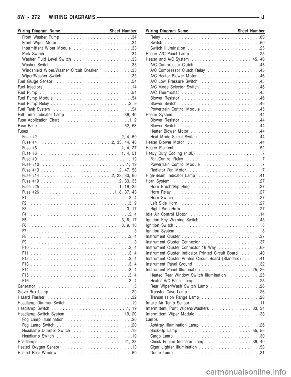
Wiring Diagram Name Sheet Number
Front Washer Pump.........................34
Front Wiper Motor..........................34
Intermittent Wiper Module.....................33
Park Switch..............................34
Washer Fluid Level Switch.....................33
Washer Switch............................33
Windshield Wiper/Washer Circuit Breaker...........33
Wiper/Washer Switch........................33
Fuel Gauge Sensor...........................54
Fuel Injectors...............................14
Fuel Pump.................................54
Fuel Pump Module...........................54
Fuel Pump Relay............................3,9
Fuel Tank System............................54
Full Time Indicator Lamp.....................39, 40
Fuse Application Chart........................1,2
Fuse Panel..............................62, 63
Fuses
Fuse #2.............................2,4,60
Fuse #4..........................2,33,44,46
Fuse #5.............................1,4,27
Fuse #6.............................1,4,51
Fuse #9...............................1,19
Fuse #10..............................1,19
Fuse #13............................2,47,58
Fuse #14.........................2,23,33,60
Fuse #19............................2,33,35
Fuse #25............................1,19,25
Fuse #26..........................1,8,37,43
F1 ...................................3,4
F2 ...................................3,9
F3 ...................................3,17
F4 ...................................3,4
F5 .................................3,6,17
F6 .................................3,9,10
F7 .....................................3
F8 ...................................3,4
F9 .....................................3
F10 ...................................3,4
F11 ...................................3,4
F12 ...................................3,4
F13 ...................................3,4
F14 ...................................3,4
F15 ...................................3,4
F16 ...................................3,4
Generator..................................5
Glove Box Lamp.............................29
Hazard Flasher..............................32
Headlamp Dimmer Switch.......................19
Headlamp Switch...........................1,19
Headlamp Switch System.....................19, 20
Fog Lamp Illumination........................20
Fog Lamp Switch...........................20
Headlamp Dimmer Switch.....................19
Headlamp Switch...........................19
Headlamps..............................21, 22
Heated Oxygen Sensor.........................13
Heated Rear Window..........................60Wiring Diagram Name Sheet Number
Relay...................................60
Switch..................................60
Switch Illumination..........................25
Heater A/C Panel Lamp........................25
Heater and A/C System......................45, 46
A/C Compressor Clutch.......................45
A/C Compressor Clutch Relay...................45
A/C Heater Blower Motor......................46
A/C Low Pressure Switch.....................45
A/C Mode Selector Switch.....................46
A/C Thermostat............................45
Blower Resistor............................46
Blower Switch.............................46
Powertrain Control Module.....................45
Heater System..............................44
Blower Resistor............................44
Blower Switch.............................44
Heater Blower Motor.........................44
Heat Mode Select Switch......................44
Heater Blower Motor..........................44
Heater Element..............................52
Heavy Duty Cooling (4.0L).......................7
Fan Control Relay...........................7
Powertrain Control Module.....................7
Radiator Fan Motor..........................7
High-Beam Indicator Lamp......................41
Horn System...............................27
Horn Brush/Slip Ring........................27
Horn Relay...............................27
Horn Switch..............................27
Left Side Horn.............................27
Right Side Horn............................27
Idle Air Control Motor.........................14
Ignition Key Warning Switch.....................43
Ignition Switch...............................8
Ignition System..............................8
Instrument Cluster............................37
Instrument Cluster Connector.....................37
Instrument Cluster Connector 16 Way...............69
Instrument Cluster Indicator Printed Circuit Board.......40
Instrument Cluster Printed Circuit Board (Standard)......41
Instrument Panel Ground.......................32
Instrument Panel Illumination..................25, 26
Heated Rear Window Switch Illumination...........25
Heater A/C Panel Lamp.......................25
Rear Wiper/Wash Switch Lamp..................26
Transfer Case Lamp.........................26
Transmission Range Lamp.....................26
Intake Air Temp Sensor........................11
Intermittent Front Wipers/Washers...............33, 34
Intermittent Wiper Module.......................33
Lamps
Ashtray Illumination Lamp.....................26
Back-Up Lamp..........................55, 56
Cargo Lamp..............................30
Check Engine Indicator Lamp................39, 40
Cigar Lighter Illumination......................58
Dome Lamp..............................31
8W - 272 WIRING DIAGRAMSJ
Page 766 of 1784
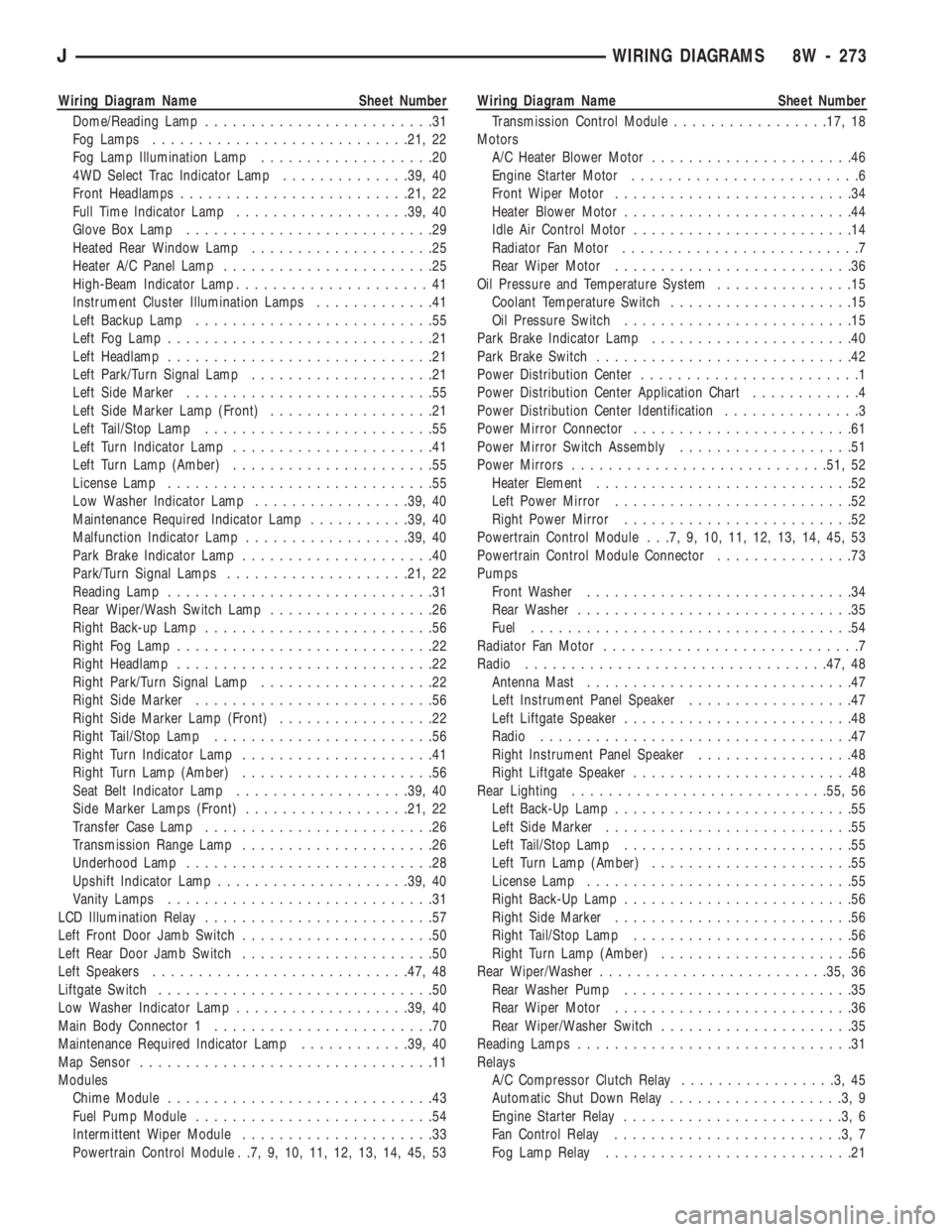
Wiring Diagram Name Sheet Number
Dome/Reading Lamp.........................31
Fog Lamps............................21, 22
Fog Lamp Illumination Lamp...................20
4WD Select Trac Indicator Lamp..............39, 40
Front Headlamps.........................21, 22
Full Time Indicator Lamp...................39, 40
Glove Box Lamp...........................29
Heated Rear Window Lamp....................25
Heater A/C Panel Lamp.......................25
High-Beam Indicator Lamp.....................41
Instrument Cluster Illumination Lamps.............41
Left Backup Lamp..........................55
Left Fog Lamp.............................21
Left Headlamp.............................21
Left Park/Turn Signal Lamp....................21
Left Side Marker...........................55
Left Side Marker Lamp (Front)..................21
Left Tail/Stop Lamp.........................55
Left Turn Indicator Lamp......................41
Left Turn Lamp (Amber)......................55
License Lamp.............................55
Low Washer Indicator Lamp.................39, 40
Maintenance Required Indicator Lamp...........39, 40
Malfunction Indicator Lamp..................39, 40
Park Brake Indicator Lamp.....................40
Park/Turn Signal Lamps....................21, 22
Reading Lamp.............................31
Rear Wiper/Wash Switch Lamp..................26
Right Back-up Lamp.........................56
Right Fog Lamp............................22
Right Headlamp............................22
Right Park/Turn Signal Lamp...................22
Right Side Marker..........................56
Right Side Marker Lamp (Front).................22
Right Tail/Stop Lamp........................56
Right Turn Indicator Lamp.....................41
Right Turn Lamp (Amber).....................56
Seat Belt Indicator Lamp...................39, 40
Side Marker Lamps (Front)..................21, 22
Transfer Case Lamp.........................26
Transmission Range Lamp.....................26
Underhood Lamp...........................28
Upshift Indicator Lamp.....................39, 40
Vanity Lamps.............................31
LCD Illumination Relay.........................57
Left Front Door Jamb Switch.....................50
Left Rear Door Jamb Switch.....................50
Left Speakers............................47, 48
Liftgate Switch..............................50
Low Washer Indicator Lamp...................39, 40
Main Body Connector 1........................70
Maintenance Required Indicator Lamp............39, 40
Map Sensor................................11
Modules
Chime Module.............................43
Fuel Pump Module..........................54
Intermittent Wiper Module.....................33
Powertrain Control Module . .7, 9, 10, 11, 12, 13, 14, 45, 53Wiring Diagram Name Sheet Number
Transmission Control Module.................17, 18
Motors
A/C Heater Blower Motor......................46
Engine Starter Motor.........................6
Front Wiper Motor..........................34
Heater Blower Motor.........................44
Idle Air Control Motor........................14
Radiator Fan Motor..........................7
Rear Wiper Motor..........................36
Oil Pressure and Temperature System...............15
Coolant Temperature Switch....................15
Oil Pressure Switch.........................15
Park Brake Indicator Lamp......................40
Park Brake Switch............................42
Power Distribution Center........................1
Power Distribution Center Application Chart............4
Power Distribution Center Identification...............3
Power Mirror Connector........................61
Power Mirror Switch Assembly...................51
Power Mirrors............................51, 52
Heater Element............................52
Left Power Mirror..........................52
Right Power Mirror.........................52
Powertrain Control Module . . .7, 9, 10, 11, 12, 13, 14, 45, 53
Powertrain Control Module Connector...............73
Pumps
Front Washer.............................34
Rear Washer..............................35
Fuel...................................54
Radiator Fan Motor............................7
Radio.................................47, 48
Antenna Mast.............................47
Left Instrument Panel Speaker..................47
Left Liftgate Speaker.........................48
Radio..................................47
Right Instrument Panel Speaker.................48
Right Liftgate Speaker........................48
Rear Lighting............................55, 56
Left Back-Up Lamp..........................55
Left Side Marker...........................55
Left Tail/Stop Lamp.........................55
Left Turn Lamp (Amber)......................55
License Lamp.............................55
Right Back-Up Lamp.........................56
Right Side Marker..........................56
Right Tail/Stop Lamp........................56
Right Turn Lamp (Amber).....................56
Rear Wiper/Washer.........................35, 36
Rear Washer Pump.........................35
Rear Wiper Motor..........................36
Rear Wiper/Washer Switch.....................35
Reading Lamps..............................31
Relays
A/C Compressor Clutch Relay.................3,45
Automatic Shut Down Relay...................3,9
Engine Starter Relay........................3,6
Fan Control Relay.........................3,7
Fog Lamp Relay...........................21
JWIRING DIAGRAMS 8W - 273
Page 768 of 1784
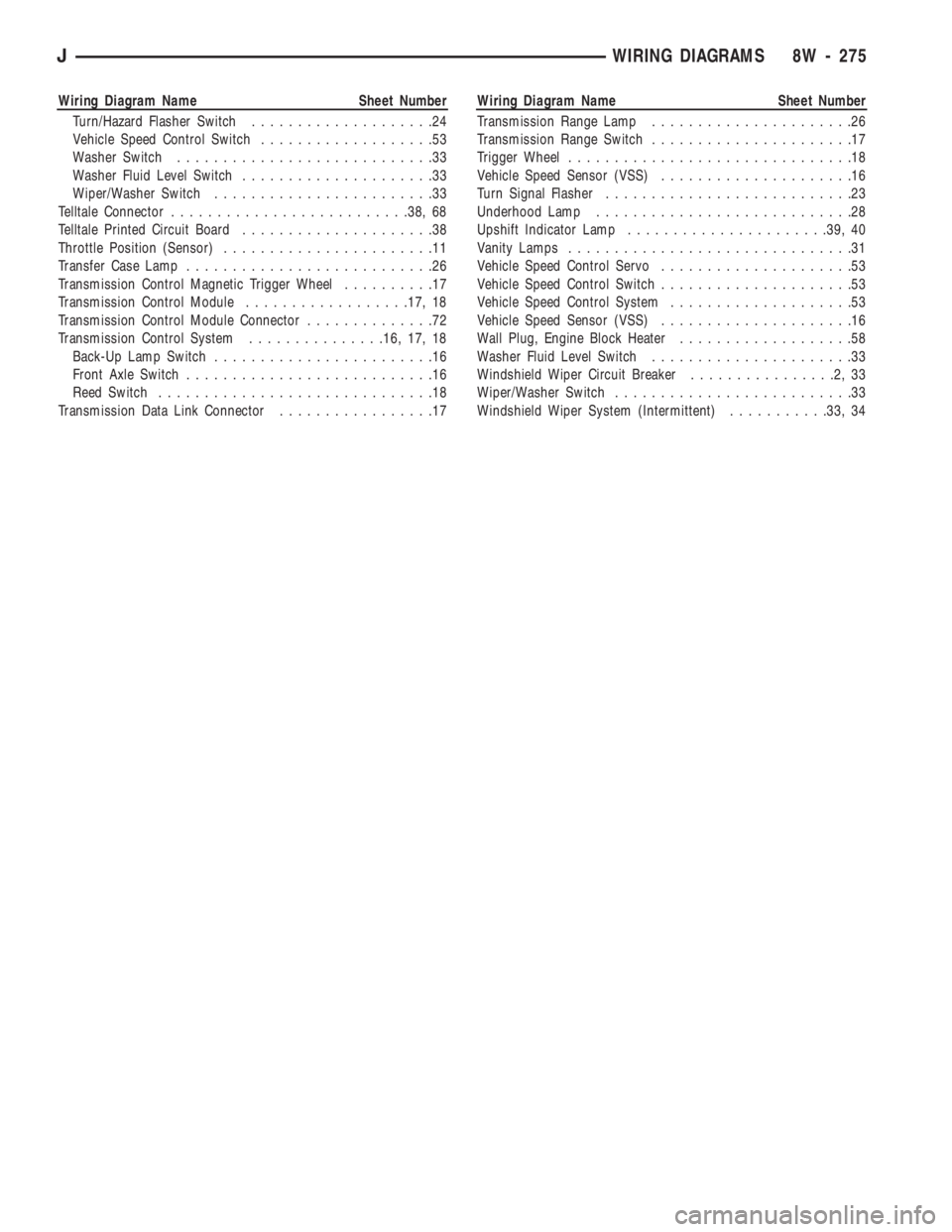
Wiring Diagram Name Sheet Number
Turn/Hazard Flasher Switch....................24
Vehicle Speed Control Switch...................53
Washer Switch............................33
Washer Fluid Level Switch.....................33
Wiper/Washer Switch........................33
Telltale Connector..........................38, 68
Telltale Printed Circuit Board.....................38
Throttle Position (Sensor).......................11
Transfer Case Lamp...........................26
Transmission Control Magnetic Trigger Wheel..........17
Transmission Control Module..................17, 18
Transmission Control Module Connector..............72
Transmission Control System...............16, 17, 18
Back-Up Lamp Switch........................16
Front Axle Switch...........................16
Reed Switch..............................18
Transmission Data Link Connector.................17Wiring Diagram Name Sheet Number
Transmission Range Lamp......................26
Transmission Range Switch......................17
Trigger Wheel...............................18
Vehicle Speed Sensor (VSS).....................16
Turn Signal Flasher...........................23
Underhood Lamp............................28
Upshift Indicator Lamp......................39, 40
Vanity Lamps...............................31
Vehicle Speed Control Servo.....................53
Vehicle Speed Control Switch.....................53
Vehicle Speed Control System....................53
Vehicle Speed Sensor (VSS).....................16
Wall Plug, Engine Block Heater...................58
Washer Fluid Level Switch......................33
Windshield Wiper Circuit Breaker................2,33
Wiper/Washer Switch..........................33
Windshield Wiper System (Intermittent)...........33, 34
JWIRING DIAGRAMS 8W - 275
Page 845 of 1784

CONNECTING ROD BEARING CLEARANCE
Engine connecting rod bearing clearances can be
determined by use of Plastigage, or equivalent. The
following is the recommended procedures for the use
of Plastigage:
(1) Remove oil film from surface to be checked.
Plastigage is soluble in oil.
(2) Place a piece of Plastigage across the entire
width of the bearing cap shell (Fig. 2). Position the
Plastigage approximately 6.35 mm (1/4 inch) off cen-
ter and away from the oil holes. In addition, suspect
areas can be checked by placing the Plastigage in the
suspect area.
(3) The crankshaft must be turned until the con-
necting rod to be checked starts moving toward the
top of the engine. Only then should the rod cap with
Plastigage in place be assembled. Tighten the rod
cap nut to 45 Nzm (33 ft. lbs.) torque.DO NOT ro-
tate the crankshaft or the Plastigage may be
smeared, giving inaccurate results.
(4) Remove the bearing cap and compare the width
of the flattened Plastigage with the scale provided on
the package (Fig. 3). Plastigage generally comes in 2
scales (one scale is in inches and the other is a met-
ric scale). Locate the band closest to the same width.
This band shows the amount of clearance. Differ-
ences in readings between the ends indicate the
amount of taper present. Record all readings taken
(refer to Engine Specifications).
(5) Plastigage is available in a variety of clearance
ranges. The 0.025-0.076 mm (0.001-0.003 inch) range
is usually the most appropriate for checking engine
bearing clearances.
REPAIR DAMAGED OR WORN THREADS
Damaged or worn threads can be repaired. Essen-
tially, this repair consists of:
²Drilling out worn or damaged threads.
²Tapping the hole with a special Heli-Coil Tap, or
equivalent.
²Installing an insert into the tapped hole.
This brings the hole back to its original thread size.
CAUTION: Be sure that the tapped holes maintain
the original center line.Heli-Coil tools and inserts are readily available
from automotive parts jobbers.
SERVICE ENGINE ASSEMBLY (SHORT BLOCK)
A service replacement engine assembly (short
block) may be installed whenever the original cylin-
der block is defective or damaged beyond repair. It
consists of the cylinder block, crankshaft, piston and
rod assemblies. If needed, the camshaft must be pro-
cured separately and installed before the engine is
installed in the vehicle.
A short block is identified with the letter ``S'' stamped
on the same machined surface where the build date
code is stamped for complete engine assemblies.
Installation includes the transfer of components
from the defective or damaged original engine. Fol-
low the appropriate procedures for cleaning, inspec-
tion and torque tightening.
HYDROSTATIC LOCK
When an engine is suspected of hydrostatic lock
(regardless of what caused the problem), follow the
steps below.
(1) Perform the Fuel Pressure Release Procedure
(refer to Group 14, Fuel System).
(2) Disconnect the negative cable from the battery.
(3) Inspect air cleaner, induction system and in-
take manifold to ensure system is dry and clear of
foreign material.
(4) Place a shop towel around the spark plugs to
catch any fluid that may possibly be under pressure in
the cylinder head. Remove the plugs from the engine.
CAUTION: DO NOT use the starter motor to rotate
the crankshaft. Severe damage could occur.
(5) With all spark plugs removed, rotate the crank-
shaft using a breaker bar and socket.
(6) Identify the fluid in the cylinders (i.e. coolant,
fuel, oil, etc.).
(7) Make sure all fluid has been removed from the
cylinders.
(8) Repair engine or components as necessary to
prevent this problem from occurring again.
(9) Squirt engine oil into the cylinders to lubricate
the walls. This will prevent damage on restart.
(10) Install new spark plugs. Tighten the spark
plugs to 37 Nzm (27 ft. lbs.) torque.
(11) Drain engine oil. Remove and discard the oil
filter.
(12) Install the drain plug. Tighten the plug to 34
Nzm (25 ft. lbs.) torque.
(13) Install a new oil filter.
(14) Fill engine crankcase with the specified
amount and grade of oil (refer to Group 0, Lubrica-
tion and Maintenance).
(15) Connect the negative cable to the battery.
(16) Start the engine and check for any leaks.
Fig. 3 Clearance Measurement
9 - 4 ENGINESJ