1994 JEEP CHEROKEE Transfer case
[x] Cancel search: Transfer casePage 1028 of 1784
²Have a 3 degree maximum operating angle
²Have at least a 1/2 degree continuous operating
(propeller shaft) angle
Engine speed (R.P.M.) is the main factor though in
determining maximum allowable operating angles.
As a guide to maximum normal operating angles re-
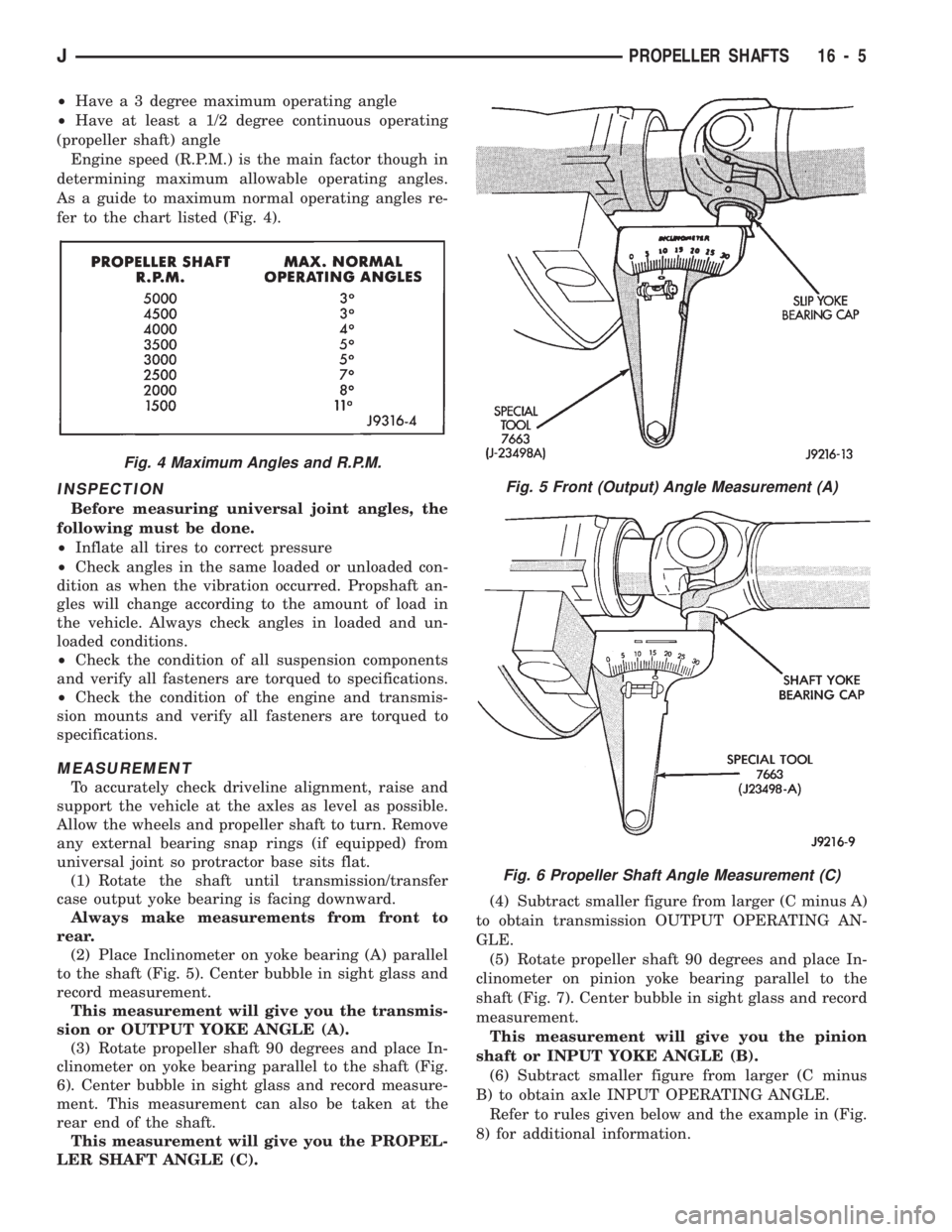
fer to the chart listed (Fig. 4).
INSPECTION
Before measuring universal joint angles, the
following must be done.
²Inflate all tires to correct pressure
²Check angles in the same loaded or unloaded con-
dition as when the vibration occurred. Propshaft an-
gles will change according to the amount of load in
the vehicle. Always check angles in loaded and un-
loaded conditions.
²Check the condition of all suspension components
and verify all fasteners are torqued to specifications.
²Check the condition of the engine and transmis-
sion mounts and verify all fasteners are torqued to
specifications.
MEASUREMENT
To accurately check driveline alignment, raise and
support the vehicle at the axles as level as possible.
Allow the wheels and propeller shaft to turn. Remove
any external bearing snap rings (if equipped) from
universal joint so protractor base sits flat.
(1) Rotate the shaft until transmission/transfer
case output yoke bearing is facing downward.
Always make measurements from front to
rear.
(2) Place Inclinometer on yoke bearing (A) parallel
to the shaft (Fig. 5). Center bubble in sight glass and
record measurement.
This measurement will give you the transmis-
sion or OUTPUT YOKE ANGLE (A).
(3) Rotate propeller shaft 90 degrees and place In-
clinometer on yoke bearing parallel to the shaft (Fig.
6). Center bubble in sight glass and record measure-
ment. This measurement can also be taken at the
rear end of the shaft.
This measurement will give you the PROPEL-
LER SHAFT ANGLE (C).(4) Subtract smaller figure from larger (C minus A)
to obtain transmission OUTPUT OPERATING AN-
GLE.
(5) Rotate propeller shaft 90 degrees and place In-
clinometer on pinion yoke bearing parallel to the
shaft (Fig. 7). Center bubble in sight glass and record
measurement.
This measurement will give you the pinion
shaft or INPUT YOKE ANGLE (B).
(6) Subtract smaller figure from larger (C minus
B) to obtain axle INPUT OPERATING ANGLE.
Refer to rules given below and the example in (Fig.
8) for additional information.
Fig. 4 Maximum Angles and R.P.M.
Fig. 5 Front (Output) Angle Measurement (A)
Fig. 6 Propeller Shaft Angle Measurement (C)
JPROPELLER SHAFTS 16 - 5
Page 1030 of 1784
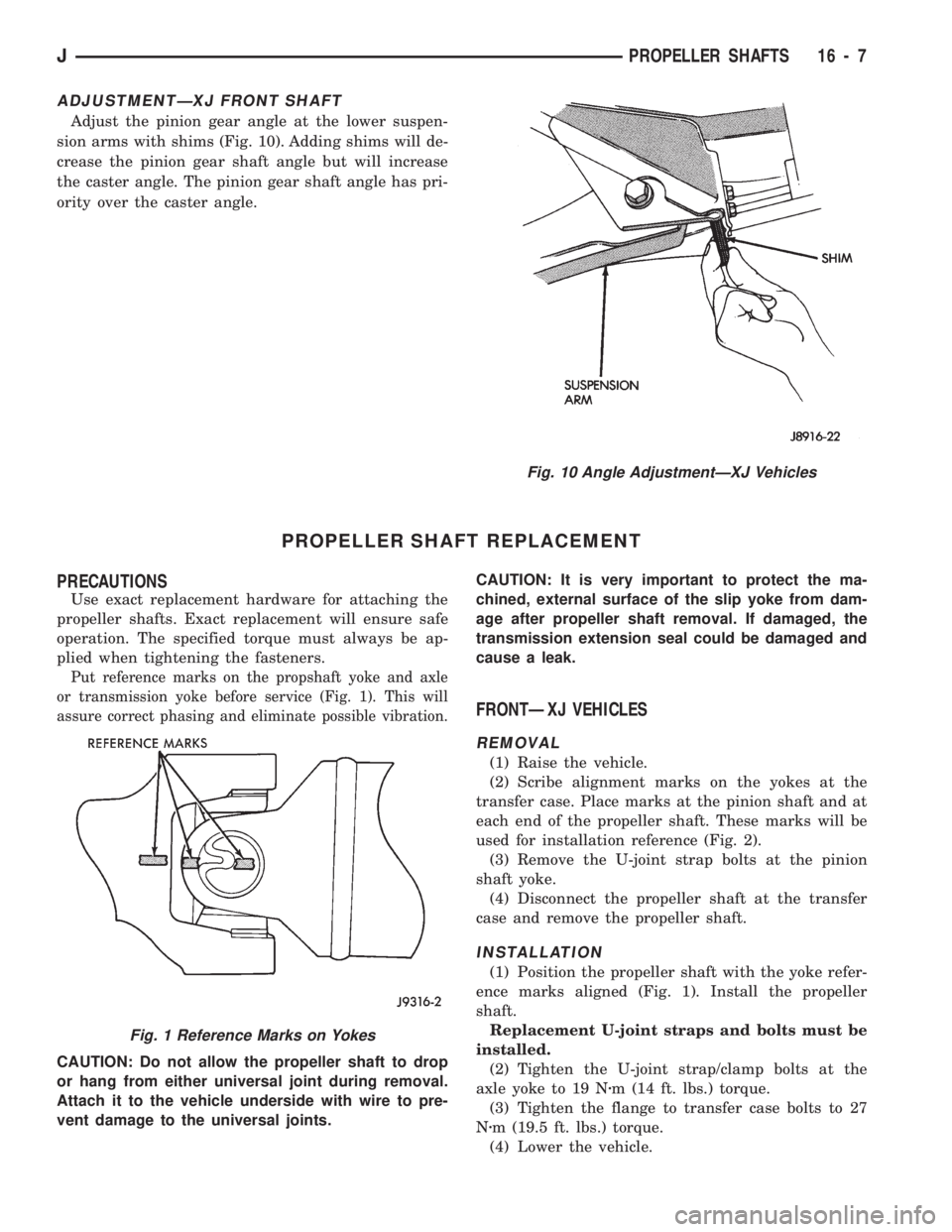
ADJUSTMENTÐXJ FRONT SHAFT
Adjust the pinion gear angle at the lower suspen-
sion arms with shims (Fig. 10). Adding shims will de-
crease the pinion gear shaft angle but will increase
the caster angle. The pinion gear shaft angle has pri-
ority over the caster angle.
PROPELLER SHAFT REPLACEMENT
PRECAUTIONS
Use exact replacement hardware for attaching the
propeller shafts. Exact replacement will ensure safe
operation. The specified torque must always be ap-
plied when tightening the fasteners.
Put reference marks on the propshaft yoke and axle
or transmission yoke before service (Fig. 1). This will
assure correct phasing and eliminate possible vibration.
CAUTION: Do not allow the propeller shaft to drop
or hang from either universal joint during removal.
Attach it to the vehicle underside with wire to pre-
vent damage to the universal joints.CAUTION: It is very important to protect the ma-
chined, external surface of the slip yoke from dam-
age after propeller shaft removal. If damaged, the
transmission extension seal could be damaged and
cause a leak.
FRONTÐXJ VEHICLES
REMOVAL
(1) Raise the vehicle.
(2) Scribe alignment marks on the yokes at the
transfer case. Place marks at the pinion shaft and at
each end of the propeller shaft. These marks will be
used for installation reference (Fig. 2).
(3) Remove the U-joint strap bolts at the pinion
shaft yoke.
(4) Disconnect the propeller shaft at the transfer
case and remove the propeller shaft.
INSTALLATION
(1) Position the propeller shaft with the yoke refer-
ence marks aligned (Fig. 1). Install the propeller
shaft.
Replacement U-joint straps and bolts must be
installed.
(2) Tighten the U-joint strap/clamp bolts at the
axle yoke to 19 Nzm (14 ft. lbs.) torque.
(3) Tighten the flange to transfer case bolts to 27
Nzm (19.5 ft. lbs.) torque.
(4) Lower the vehicle.
Fig. 10 Angle AdjustmentÐXJ Vehicles
Fig. 1 Reference Marks on Yokes
JPROPELLER SHAFTS 16 - 7
Page 1031 of 1784
REARÐXJ,YJ VEHICLES
REMOVAL
(1) Shift the transmission and transfer case (if ap-
plicable) to their Neutral positions. Raise the vehicle.
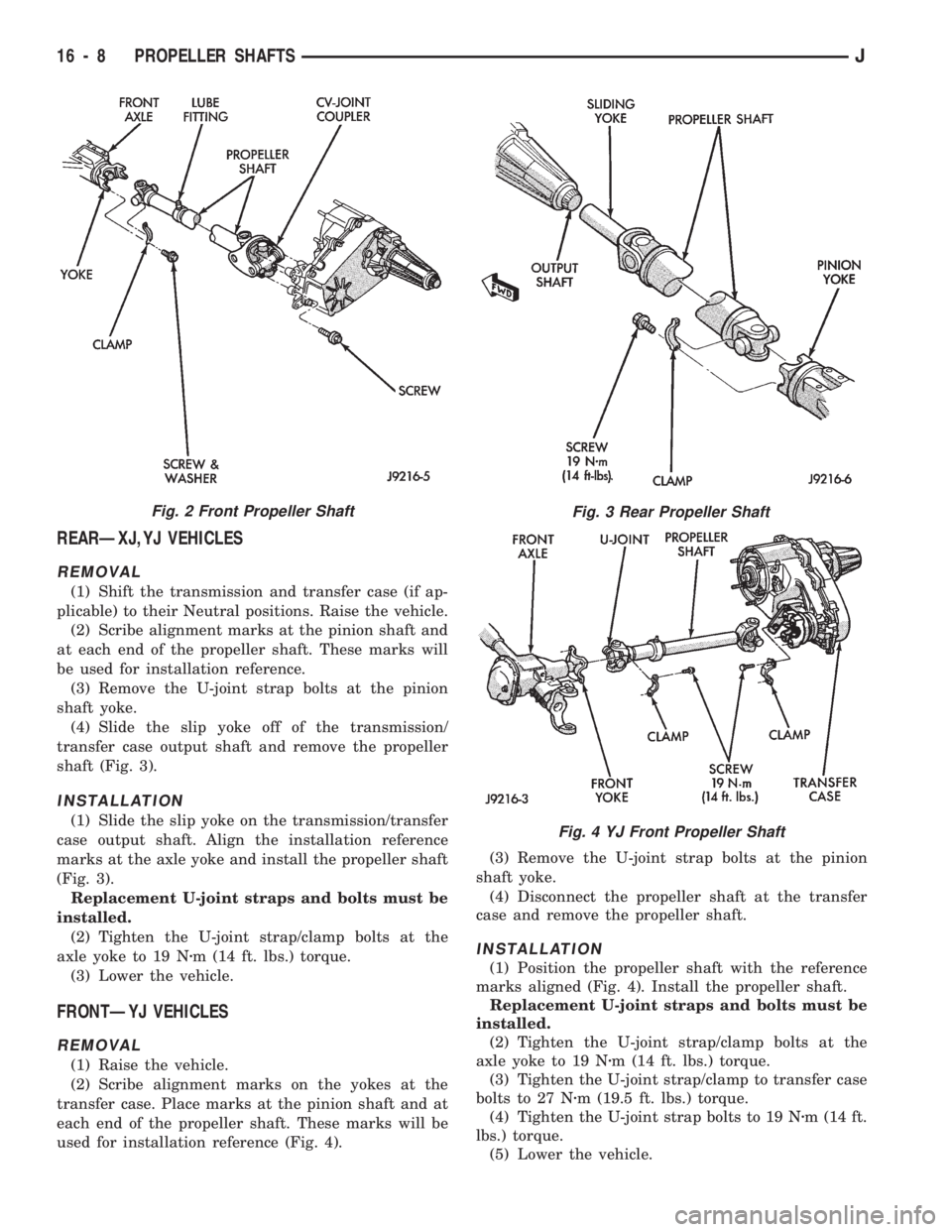
(2) Scribe alignment marks at the pinion shaft and
at each end of the propeller shaft. These marks will
be used for installation reference.
(3) Remove the U-joint strap bolts at the pinion
shaft yoke.
(4) Slide the slip yoke off of the transmission/
transfer case output shaft and remove the propeller
shaft (Fig. 3).
INSTALLATION
(1) Slide the slip yoke on the transmission/transfer
case output shaft. Align the installation reference
marks at the axle yoke and install the propeller shaft
(Fig. 3).
Replacement U-joint straps and bolts must be
installed.
(2) Tighten the U-joint strap/clamp bolts at the
axle yoke to 19 Nzm (14 ft. lbs.) torque.
(3) Lower the vehicle.
FRONTÐYJ VEHICLES
REMOVAL
(1) Raise the vehicle.
(2) Scribe alignment marks on the yokes at the
transfer case. Place marks at the pinion shaft and at
each end of the propeller shaft. These marks will be
used for installation reference (Fig. 4).(3) Remove the U-joint strap bolts at the pinion
shaft yoke.
(4) Disconnect the propeller shaft at the transfer
case and remove the propeller shaft.
INSTALLATION
(1) Position the propeller shaft with the reference
marks aligned (Fig. 4). Install the propeller shaft.
Replacement U-joint straps and bolts must be
installed.
(2) Tighten the U-joint strap/clamp bolts at the
axle yoke to 19 Nzm (14 ft. lbs.) torque.
(3) Tighten the U-joint strap/clamp to transfer case
bolts to 27 Nzm (19.5 ft. lbs.) torque.
(4) Tighten the U-joint strap bolts to 19 Nzm (14 ft.
lbs.) torque.
(5) Lower the vehicle.
Fig. 3 Rear Propeller Shaft
Fig. 4 YJ Front Propeller Shaft
Fig. 2 Front Propeller Shaft
16 - 8 PROPELLER SHAFTSJ
Page 1112 of 1784
TRANSMISSION AND TRANSFER CASE
CONTENTS
page page
30RH/32RH AUTOMATIC TRANSMISSION . . . 66
AW-4 AUTOMATIC TRANSMISSION........ 156AX 15 MANUAL TRANSMISSION.......... 32
AX 4/5 MANUAL TRANSMISSION........... 1
AX 4/5 MANUAL TRANSMISSION
INDEX
page page
Cleaning and Inspection................... 13
Gear Ratios............................. 2
General Information........................ 1
Recommended Lubricant.................... 2
Service Diagnosis......................... 2
Shift Pattern............................. 2Transmission Assembly and Adjustment....... 15
Transmission Disassembly and Overhaul........ 5
Transmission Identification................... 1
Transmission Installation.................... 4
Transmission Removal..................... 3
GENERAL INFORMATION
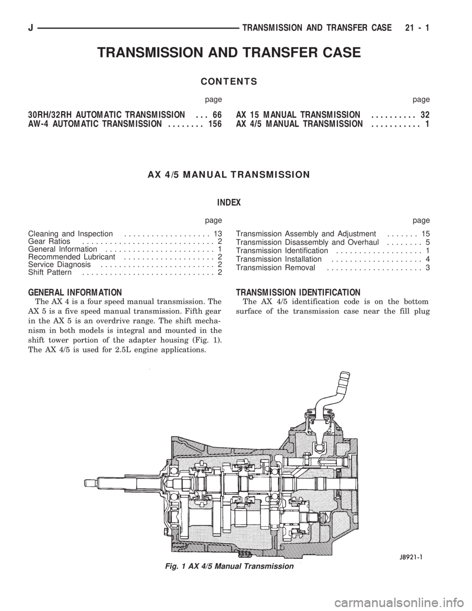
The AX 4 is a four speed manual transmission. The
AX 5 is a five speed manual transmission. Fifth gear
in the AX 5 is an overdrive range. The shift mecha-
nism in both models is integral and mounted in the
shift tower portion of the adapter housing (Fig. 1).
The AX 4/5 is used for 2.5L engine applications.
TRANSMISSION IDENTIFICATION
The AX 4/5 identification code is on the bottom
surface of the transmission case near the fill plug
Fig. 1 AX 4/5 Manual Transmission
JTRANSMISSION AND TRANSFER CASE 21 - 1
Page 1114 of 1784
A correct lubricant level check can only be made
when the vehicle is level; use a drive-on hoist to en-
sure this. Also allow the lubricant to settle for a
minute or so before checking. These recommenda-
tions will ensure an accurate check and avoid an un-
der-or-overfill condition.
HARD SHIFTING
Hard shifting is usually caused by a low lubricant
level, improper or contaminated lubricants, compo-
nent damage, incorrect clutch adjustment, or by a
damaged clutch pressure plate or disc.
Substantial lubricant leaks can result in gear, shift
rail, synchro and bearing damage. If a leak goes un-
detected for an extended period, the first indications
of a problem are usually hard shifting and noise.
Incorrect or contaminated lubricants can also con-
tribute to hard shifting. The consequence of using
non-recommended lubricants is noise, excessive wear,
internal bind and hard shifting.
Improper clutch release is a frequent cause of hard
shifting. Incorrect adjustment or a worn, damaged
pressure plate or disc can cause incorrect release. If
the clutch problem is advanced, gear clash during
shifts can result.
Worn or damaged synchro rings can cause gear
clash when shifting into any forward gear. In some
new or rebuilt transmissions, new synchro rings maytend to stick slightly causing hard or noisy shifts. In
most cases, this condition will decline as the rings
wear-in.
TRANSMISSION NOISE
Most manual transmissions make some noise dur-
ing normal operation. Rotating gears can generate a
mild whine that may only be audible at extreme
speeds.
Severe, obviously audible transmission noise is
generally the result of a lubricant problem. Insuffi-
cient, improper, or contaminated lubricant can pro-
mote rapid wear of gears, synchros, shift rails, forks
and bearings. The overheating caused by a lubricant
problem, can also lead to gear breakage.
TRANSMISSION REMOVAL
(1) Shift transmission into first or third gear. Then
raise vehicle on hoist.
(2) Support engine with adjustable jack stand. Be
sure to position wood block between jack and oil pan.
(3) Disconnect necessary exhaust system compo-
nents.
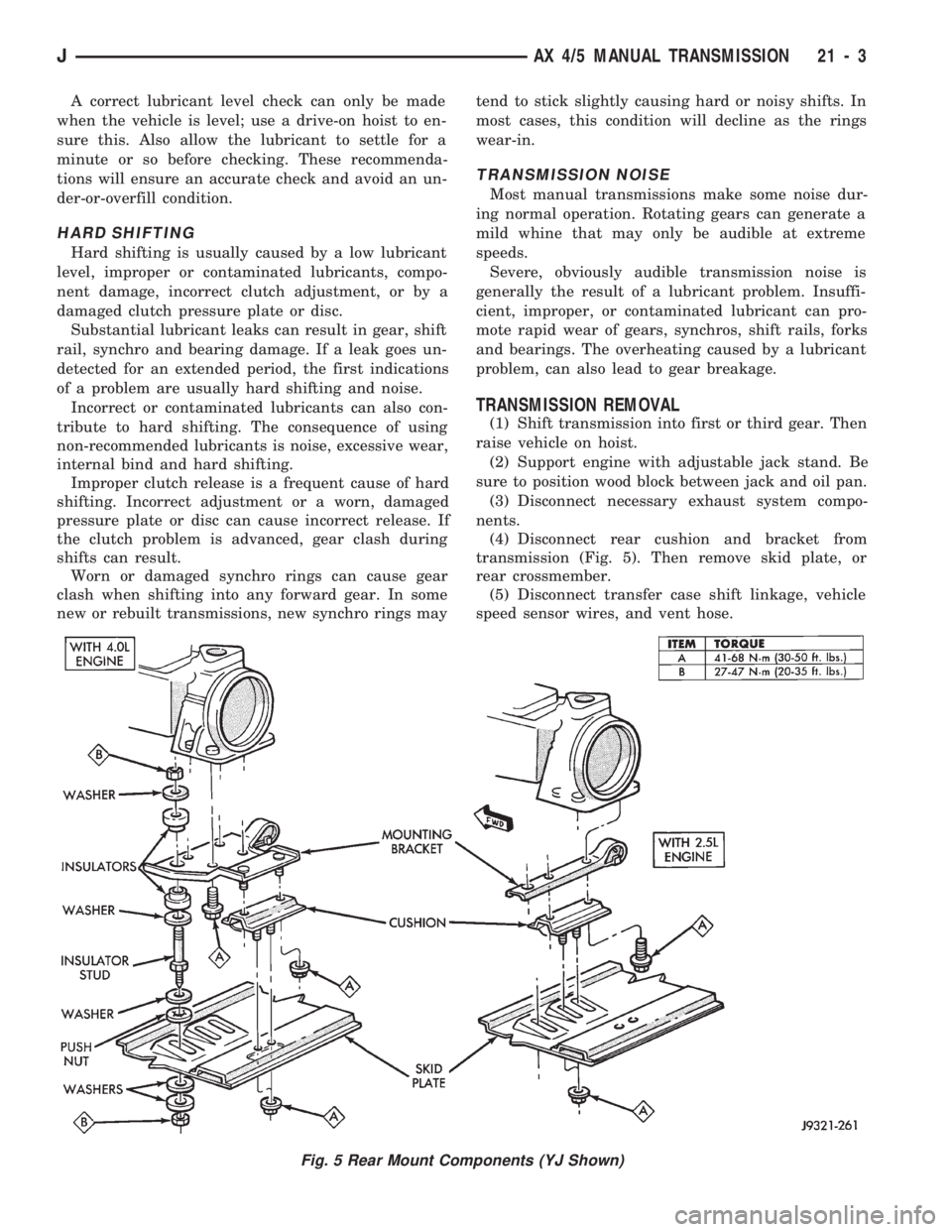
(4) Disconnect rear cushion and bracket from
transmission (Fig. 5). Then remove skid plate, or
rear crossmember.
(5) Disconnect transfer case shift linkage, vehicle
speed sensor wires, and vent hose.
Fig. 5 Rear Mount Components (YJ Shown)
JAX 4/5 MANUAL TRANSMISSION 21 - 3
Page 1115 of 1784
(6) Remove slave cylinder from clutch housing.
(7) Disconnect transmission shift lever as follows:
(a) Lower transmission-transfer case assembly ap-
proximately 7-8 cm (3 in.) for access to shift lever.
(b) Reach up and around transmission case and
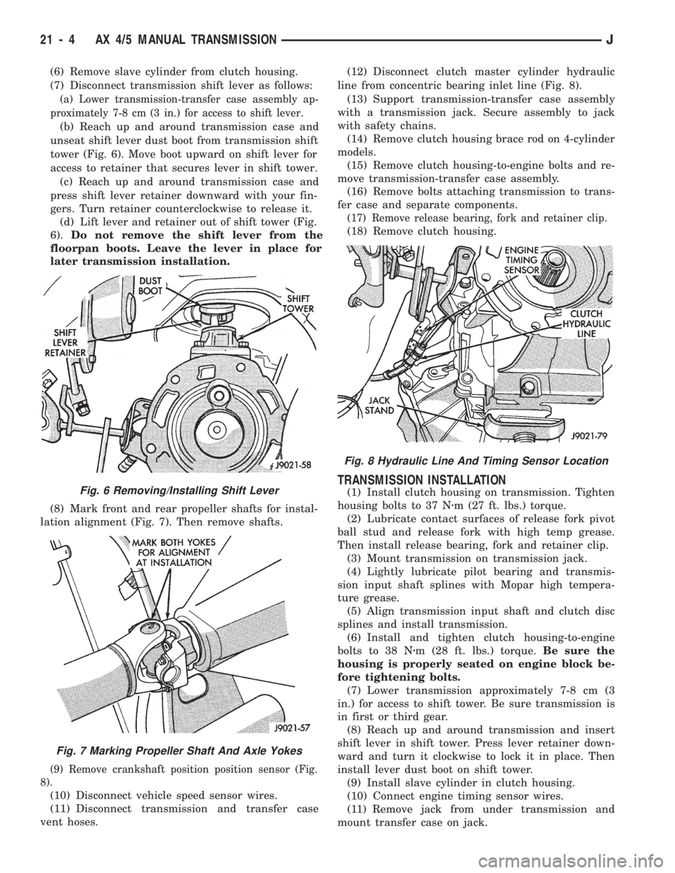
unseat shift lever dust boot from transmission shift
tower (Fig. 6). Move boot upward on shift lever for
access to retainer that secures lever in shift tower.
(c) Reach up and around transmission case and
press shift lever retainer downward with your fin-
gers. Turn retainer counterclockwise to release it.
(d) Lift lever and retainer out of shift tower (Fig.
6).Do not remove the shift lever from the
floorpan boots. Leave the lever in place for
later transmission installation.
(8) Mark front and rear propeller shafts for instal-
lation alignment (Fig. 7). Then remove shafts.
(9) Remove crankshaft position position sensor (Fig.
8).
(10) Disconnect vehicle speed sensor wires.
(11) Disconnect transmission and transfer case
vent hoses.(12) Disconnect clutch master cylinder hydraulic
line from concentric bearing inlet line (Fig. 8).
(13) Support transmission-transfer case assembly
with a transmission jack. Secure assembly to jack
with safety chains.
(14) Remove clutch housing brace rod on 4-cylinder
models.
(15) Remove clutch housing-to-engine bolts and re-
move transmission-transfer case assembly.
(16) Remove bolts attaching transmission to trans-
fer case and separate components.
(17) Remove release bearing, fork and retainer clip.
(18) Remove clutch housing.
TRANSMISSION INSTALLATION
(1) Install clutch housing on transmission. Tighten
housing bolts to 37 Nzm (27 ft. lbs.) torque.
(2) Lubricate contact surfaces of release fork pivot
ball stud and release fork with high temp grease.
Then install release bearing, fork and retainer clip.
(3) Mount transmission on transmission jack.
(4) Lightly lubricate pilot bearing and transmis-
sion input shaft splines with Mopar high tempera-
ture grease.
(5) Align transmission input shaft and clutch disc
splines and install transmission.
(6) Install and tighten clutch housing-to-engine
bolts to 38 Nzm (28 ft. lbs.) torque.Be sure the
housing is properly seated on engine block be-
fore tightening bolts.
(7) Lower transmission approximately 7-8 cm (3
in.) for access to shift tower. Be sure transmission is
in first or third gear.
(8) Reach up and around transmission and insert
shift lever in shift tower. Press lever retainer down-
ward and turn it clockwise to lock it in place. Then
install lever dust boot on shift tower.
(9) Install slave cylinder in clutch housing.
(10) Connect engine timing sensor wires.
(11) Remove jack from under transmission and
mount transfer case on jack.Fig. 6 Removing/Installing Shift Lever
Fig. 7 Marking Propeller Shaft And Axle Yokes
Fig. 8 Hydraulic Line And Timing Sensor Location
21 - 4 AX 4/5 MANUAL TRANSMISSIONJ
Page 1116 of 1784
(12) Align transfer case and transmission shafts
and install transfer case. Tighten transfer case-to-
transmission nuts/bolts to 35 Nzm (26 ft. lbs.) torque.
(13) Remove jack stand from under engine and re-
position jack under transmission. Then remove trans-
mission jack.
(14) Connect transfer case vent hose and shift link-
age. Check and adjust linkage if necessary.
(15) Connect transmission and transfer case vent
hoses.
(16) Connect backup light switch wires.
(17) Connect vehicle speed sensor wires.
(18) Install and connect crankshaft position sensor
if equipped.
(19) Install rear crossmember, or skid plate (Fig. 5).
On XJ, tighten crossmember-to-frame bolts to 41 Nzm
(31 ft. lbs.) torque. Then tighten transmission-to-rear
support bolts/nuts to 45 Nzm (33 ft. lbs.) torque. On YJ,
tighten bolts/nuts to indicated torque (Fig. 5).
(20) Align and install front/rear propeller shafts.
Tighten shaft U-joint clamp bolts to 19 Nzm (170 in.
lbs.) torque.
(21) On XJ, install skid plate, if removed. Tighten
bolts to 42 Nzm (31 ft. lbs.) torque. Tighten stud nuts
to 17 Nzm (150 in. lbs.) torque.
(22) Top off transmission and transfer case lubri-
cant levels.
(23) Lower vehicle.
TRANSMISSION DISASSEMBLY AND OVERHAUL
ADAPTER HOUSING AND FRONT BEARING
RETAINER REMOVAL
(1) Drain transmission lubricant.
(2) Remove concentric bearing.
(3) Remove clutch housing bolts and remove housing.
(4) On 2-wheel drive models, remove vehicle speed
sensor, speedometer adapter and speedometer driven
gear. Then remove extension housing seal (Fig. 9).(5) Remove detent spring and ball. Remove detent
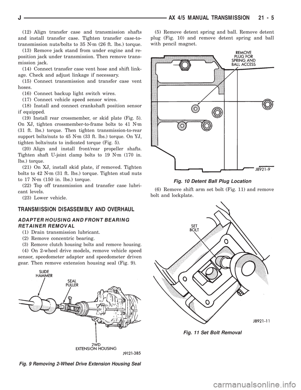
plug (Fig. 10) and remove detent spring and ball
with pencil magnet.
(6) Remove shift arm set bolt (Fig. 11) and remove
bolt and lockplate.
Fig. 10 Detent Ball Plug Location
Fig. 11 Set Bolt Removal
Fig. 9 Removing 2-Wheel Drive Extension Housing Seal
JAX 4/5 MANUAL TRANSMISSION 21 - 5
Page 1143 of 1784
AX 15 MANUAL TRANSMISSION
INDEX
page page
General Information....................... 32
Service Diagnosis........................ 33
Transmission Assembly and Adjustment....... 51
Transmission Disassembly and Overhaul....... 36
Transmission Gear Ratios.................. 33
Transmission Identification.................. 32Transmission InstallationÐAX 15............. 35
Transmission Lubricant.................... 33
Transmission RemovalÐAX 15.............. 34
Transmission Shift Pattern.................. 33
Transmission Switch and Plug Locations....... 33
GENERAL INFORMATION
The AX 15 is a 5-speed, synchromesh, manual
transmission. Fifth gear is an overdrive range with a
ratio of 0.79:1. The shift mechanism is integral and
mounted in the shift tower portion of the adapter
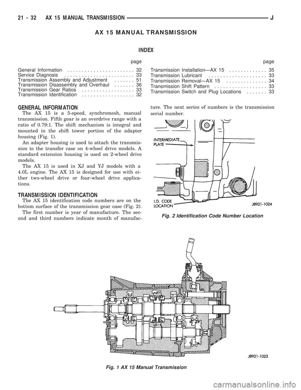
housing (Fig. 1).
An adapter housing is used to attach the transmis-
sion to the transfer case on 4-wheel drive models. A
standard extension housing is used on 2-wheel drive
models.
The AX 15 is used in XJ and YJ models with a
4.0L engine. The AX 15 is designed for use with ei-
ther two-wheel drive or four-wheel drive applica-
tions.
TRANSMISSION IDENTIFICATION
The AX 15 identification code numbers are on the
bottom surface of the transmission gear case (Fig. 2).
The first number is year of manufacture. The sec-
ond and third numbers indicate month of manufac-ture. The next series of numbers is the transmission
serial number.
Fig. 1 AX 15 Manual Transmission
Fig. 2 Identification Code Number Location
21 - 32 AX 15 MANUAL TRANSMISSIONJ