1994 JEEP CHEROKEE Transfer case
[x] Cancel search: Transfer casePage 859 of 1784

(14) Install the remaining flywheel housing bolts.
Tighten the bolts to 38 Nzm (28 ft. lbs.) torque.
(15) Install the starter motor and connect the ca-
ble. Tighten the bolts to 45 Nzm (33 ft. lbs.) torque.
(16) Install the oil filter.
(17) Lower the vehicle.
(18) Connect the coolant hoses and tighten the
clamps.
(19) If equipped with power steering:
(a) Remove the protective caps
(b) Connect the hoses to the fittings at the steer-
ing gear. Tighten the nut to 52 Nzm (38 ft. lbs.)
torque.
(c) Fill the pump reservoir with fluid.
(20) Remove the pulley-to-water pump flange
alignment capscrew and install the fan and spacer or
Tempatrol fan assembly.
(21) Tighten the serpentine drive belt according to
the specifications listed in Group 7, Cooling System.
(22) Install the fan shroud and radiator.
(23) Connect the radiator hoses.
(24) Connect the heater hoses.
(25) Connect the throttle valve rod and retainer.
(26) Connect the throttle cable and install the rod.
(27) Install the throttle valve rod spring.
(28) Connect the speed control cable, if equipped.
(29) Connect the oxygen sensor wire connector.
(30) Install the vacuum hose and check valve on
the brake booster.
(31) Connect the coolant temperature sensor wire
connector.
(32) Connect the idle speed actuator wire connec-
tor.
(33) Connect the fuel inlet and return hoses at the
fuel rail. Verify that the quick-connect fitting assem-
bly fits securely over the fuel lines by giving the fuel
lines a firm tug.
(34) Install the fuel line bracket to the intake
manifold.
(35) Connect all fuel injection wire connections.
(36) Install the engine ground strap.
(37) Connect the ignition coil wire connector.
(38) Remove the coolant temperature sending unit
to permit air to escape from the block. Fill the cool-
ing system with coolant. Install the coolant tempera-
ture sending unit when the system is filled.
(39) Install the battery and connect the battery ca-
bles.
(40) Install the air cleaner bonnet to the throttle
body.
(41) Install the air cleaner.
(42) Lower the hood and secure in place.
(43) Start the engine and inspect for leaks.
(44) Stop the engine and check the fluid levels.
Add fluid, as required.ENGINE CYLINDER HEAD COVER
A cured gasket is part of the engine cylinder head
cover.
REMOVAL
(1) Disconnect negative cable from battery.
(2) Disconnect the Crankcase Ventilation (CCV)
vacuum hose from engine cylinder head cover (Fig.
1).
(3) Disconnect the fresh air inlet hose from the en-
gine cylinder head cover (Fig. 1).
(4) Remove the engine cylinder head cover mount-
ing bolts.
(5) Remove the engine cylinder head cover.
CLEANING
Remove any original sealer from the cover sealing
surface of the engine cylinder head and clean the
surface using a fabric cleaner.
Remove all residue from the sealing surface using
a clean, dry cloth.
INSPECTION
Inspect the engine cylinder head cover for cracks.
Replace the cover, if cracked.
The original grey gasket material should NOT be
removed. If sections of the gasket material are miss-
ing or are compressed, replace the engine cylinder
head cover. However, sections with minor damage
such as small cracks, cuts or chips may be repaired
with a hand held applicator. The new material must
be smoothed over to maintain gasket height. Allow
the gasket material to cure prior to engine cylinder
head cover installation.
INSTALLATION
(1) If a replacement cover is installed, transfer the
CCV valve grommet the oil filler cap from the origi-
nal cover to the replacement cover.
(2) Install engine cylinder head cover. Tighten the
mounting bolts to 10 Nzm (85 in. lbs.) torque.
Fig. 1 Engine Cylinder Head Cover
9 - 18 2.5L ENGINEJ
Page 900 of 1784
(17) Tighten the serpentine drive belt according to
the specifications listed in Group 7, Cooling System.
(18) Install the fan shroud and radiator (refer to
Group 7, Cooling System for the proper procedure).
(19) Connect the radiator hoses.
(20) Connect the throttle valve rod and retainer.
(21) Connect the throttle cable and install the rod.
(22) Install the throttle valve rod spring.
(23) Connect the speed control cable, if equipped.
(24) Connect the oxygen sensor wire connector.
(25) Install the vacuum hose and check valve on
the brake booster.
(26) Connect the coolant temperature sensor wire
connector.
(27) Connect the idle speed actuator wire connec-
tor.
(28) Connect the fuel inlet and return hoses at the
fuel rail. Verify that the quick-connect fitting assem-
bly fits securely over the fuel lines by giving the fuel
lines a firm tug.
(29) Install the fuel line bracket to the intake
manifold.
(30) Connect all fuel injection wire connections.
(31) Install the engine ground strap.
(32) Connect the ignition coil wire connector.
(33) Remove the coolant temperature sending unit
to permit air to escape from the block. Fill the cool-
ing system with coolant. Install the coolant tempera-
ture sending unit when the system is filled.
(34) If equipped with power steering:
(a) Remove the protective caps
(b) Connect the hoses to the fittings at the steer-
ing gear. Tighten the nut to 52 Nzm (38 ft. lbs.)
torque.
(c) Fill the pump reservoir with fluid.
(35) Install the battery and connect the battery ca-
bles.
(36) Install the air cleaner bonnet to the throttle
body.
(37) Install the air cleaner.
(38) Lower the hood and secure in place.
(39) Start the engine and inspect for leaks.
(40) Stop the engine and check the fluid levels.
Add fluid, as required.
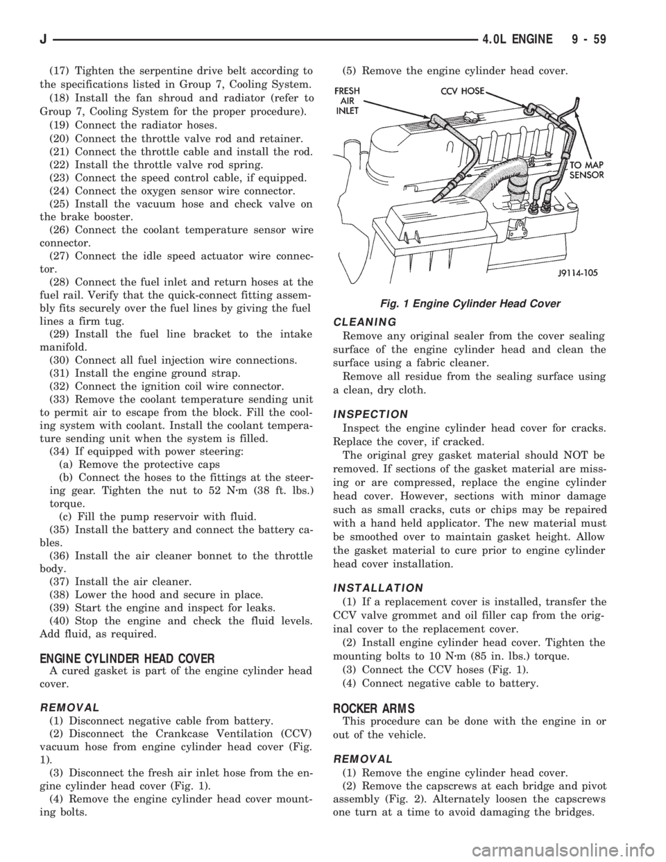
ENGINE CYLINDER HEAD COVER
A cured gasket is part of the engine cylinder head
cover.
REMOVAL
(1) Disconnect negative cable from battery.
(2) Disconnect the Crankcase Ventilation (CCV)
vacuum hose from engine cylinder head cover (Fig.
1).
(3) Disconnect the fresh air inlet hose from the en-
gine cylinder head cover (Fig. 1).
(4) Remove the engine cylinder head cover mount-
ing bolts.(5) Remove the engine cylinder head cover.
CLEANING
Remove any original sealer from the cover sealing
surface of the engine cylinder head and clean the
surface using a fabric cleaner.
Remove all residue from the sealing surface using
a clean, dry cloth.
INSPECTION
Inspect the engine cylinder head cover for cracks.
Replace the cover, if cracked.
The original grey gasket material should NOT be
removed. If sections of the gasket material are miss-
ing or are compressed, replace the engine cylinder
head cover. However, sections with minor damage
such as small cracks, cuts or chips may be repaired
with a hand held applicator. The new material must
be smoothed over to maintain gasket height. Allow
the gasket material to cure prior to engine cylinder
head cover installation.
INSTALLATION
(1) If a replacement cover is installed, transfer the
CCV valve grommet and oil filler cap from the orig-
inal cover to the replacement cover.
(2) Install engine cylinder head cover. Tighten the
mounting bolts to 10 Nzm (85 in. lbs.) torque.
(3) Connect the CCV hoses (Fig. 1).
(4) Connect negative cable to battery.
ROCKER ARMS
This procedure can be done with the engine in or
out of the vehicle.
REMOVAL
(1) Remove the engine cylinder head cover.
(2) Remove the capscrews at each bridge and pivot
assembly (Fig. 2). Alternately loosen the capscrews
one turn at a time to avoid damaging the bridges.
Fig. 1 Engine Cylinder Head Cover
J4.0L ENGINE 9 - 59
Page 955 of 1784

YJ BUMPERS AND FRAME ATTACHED COMPONENTS
INDEX
page page
Generator Splash Shield................... 14
Body.................................. 18
Engine Front Support Cushion............... 15
Frame Crossmember Cover................. 14
Front Bumper........................... 14
Fuel and Brake Fluid Tube Retainer Clip....... 16
Fuel Filter Shield and Bracket............... 17
Fuel Tank Skid Plate...................... 16Muffler and Tailpipe Heat Shields............ 17
Muffler/Tailpipe Hanger Bracket.............. 16
Rear Bumper............................ 18
Rear Jounce Bumper..................... 18
Service Information....................... 14
Tow Hooks............................. 14
Transfer Case Skid Plate.................. 15
SERVICE INFORMATION
In some cases, components in the following proce-
dures either support, or are hidden by other compo-
nents.
FRONT BUMPER
The YJ front bumper is a one-piece rail (Fig. 1). A
front crossmember cover (Fig. 1) is also installed on
all YJ vehicles.
BUMPER REMOVAL
(1) Disconnect and remove the fog lamps, if
equipped.
(2) Remove the nuts and bolts that retain the
bumper extensions to the bumper rail and remove
the extensions.
(3) Remove the nuts and bolts that attach the
bumper rail/tow hooks to the frame rails.(4) Remove the bumper rail from the frame rails.
BUMPER INSTALLATION
(1) Position the front bumper on the frame rails.
(2) Install the bolts and attach the front bumper
rail (and tow hooks, if equipped) to the frame rails.
(3) Tighten the bolts to 102 Nzm (75 ft-lbs) torque.
(4) Position the bumper extensions on the bumper
rail and install the retaining bolts.
(5) Tighten the bolts to 104 Nzm (77 ft-lbs) torque.
(6) Install the fog lamps, if equipped.
FRAME CROSSMEMBER COVER
REMOVAL
(1) Remove the screws that attach the crossmem-
ber cover and support to the frame rails.
(2) Remove the crossmember cover and support
from the frame rails.
INSTALLATION
(1) Position the support and crossmember cover on
the frame rails.
(2) Install the attaching screws.
(3) Tighten the screws to 8 Nzm (72 in-lbs) torque.
TOW HOOKS
REMOVAL
(1) Remove the two bolts that attach the tow hook
to the bumper rail and to the frame rail.
(2) Remove the tow hook.
INSTALLATION
(1) Position the tow hook on the bumper rail and
frame rail.
(2) Install the attaching bolts.
(3) Tighten the bolts to 102 Nzm (75 ft-lbs) torque.
GENERATOR SPLASH SHIELD
REMOVAL
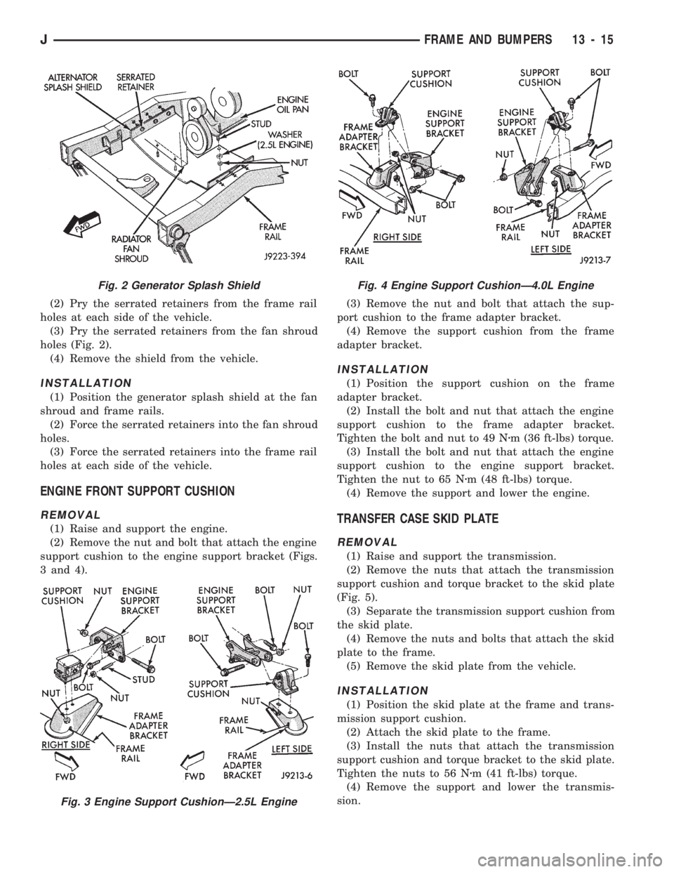
(1) Remove the shield retaining nut and washer
(Fig. 2) from the engine oil pan stud (2.5L engines
only).
Fig. 1 Front Bumper Rail, Crossmember Cover &
Tow Hooks
13 - 14 FRAME AND BUMPERSJ
Page 956 of 1784
(2) Pry the serrated retainers from the frame rail
holes at each side of the vehicle.
(3) Pry the serrated retainers from the fan shroud
holes (Fig. 2).
(4) Remove the shield from the vehicle.
INSTALLATION
(1) Position the generator splash shield at the fan
shroud and frame rails.
(2) Force the serrated retainers into the fan shroud
holes.
(3) Force the serrated retainers into the frame rail
holes at each side of the vehicle.
ENGINE FRONT SUPPORT CUSHION
REMOVAL
(1) Raise and support the engine.
(2) Remove the nut and bolt that attach the engine
support cushion to the engine support bracket (Figs.
3 and 4).(3) Remove the nut and bolt that attach the sup-
port cushion to the frame adapter bracket.
(4) Remove the support cushion from the frame
adapter bracket.
INSTALLATION
(1) Position the support cushion on the frame
adapter bracket.
(2) Install the bolt and nut that attach the engine
support cushion to the frame adapter bracket.
Tighten the bolt and nut to 49 Nzm (36 ft-lbs) torque.
(3) Install the bolt and nut that attach the engine
support cushion to the engine support bracket.
Tighten the nut to 65 Nzm (48 ft-lbs) torque.
(4) Remove the support and lower the engine.
TRANSFER CASE SKID PLATE
REMOVAL
(1) Raise and support the transmission.
(2) Remove the nuts that attach the transmission
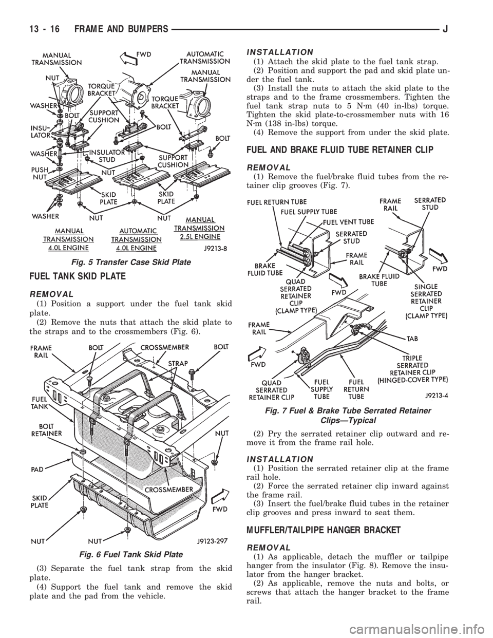
support cushion and torque bracket to the skid plate
(Fig. 5).
(3) Separate the transmission support cushion from
the skid plate.
(4) Remove the nuts and bolts that attach the skid
plate to the frame.
(5) Remove the skid plate from the vehicle.
INSTALLATION
(1) Position the skid plate at the frame and trans-
mission support cushion.
(2) Attach the skid plate to the frame.
(3) Install the nuts that attach the transmission
support cushion and torque bracket to the skid plate.
Tighten the nuts to 56 Nzm (41 ft-lbs) torque.
(4) Remove the support and lower the transmis-
sion.
Fig. 2 Generator Splash Shield
Fig. 3 Engine Support CushionÐ2.5L Engine
Fig. 4 Engine Support CushionÐ4.0L Engine
JFRAME AND BUMPERS 13 - 15
Page 957 of 1784
FUEL TANK SKID PLATE
REMOVAL
(1) Position a support under the fuel tank skid
plate.
(2) Remove the nuts that attach the skid plate to
the straps and to the crossmembers (Fig. 6).
(3) Separate the fuel tank strap from the skid
plate.
(4) Support the fuel tank and remove the skid
plate and the pad from the vehicle.
INSTALLATION
(1) Attach the skid plate to the fuel tank strap.
(2) Position and support the pad and skid plate un-
der the fuel tank.
(3) Install the nuts to attach the skid plate to the
straps and to the frame crossmembers. Tighten the
fuel tank strap nuts to 5 Nzm (40 in-lbs) torque.
Tighten the skid plate-to-crossmember nuts with 16
Nzm (138 in-lbs) torque.
(4) Remove the support from under the skid plate.
FUEL AND BRAKE FLUID TUBE RETAINER CLIP
REMOVAL
(1) Remove the fuel/brake fluid tubes from the re-
tainer clip grooves (Fig. 7).
(2) Pry the serrated retainer clip outward and re-
move it from the frame rail hole.
INSTALLATION
(1) Position the serrated retainer clip at the frame
rail hole.
(2) Force the serrated retainer clip inward against
the frame rail.
(3) Insert the fuel/brake fluid tubes in the retainer
clip grooves and press inward to seat them.
MUFFLER/TAILPIPE HANGER BRACKET
REMOVAL
(1) As applicable, detach the muffler or tailpipe
hanger from the insulator (Fig. 8). Remove the insu-
lator from the hanger bracket.
(2) As applicable, remove the nuts and bolts, or
screws that attach the hanger bracket to the frame
rail.
Fig. 5 Transfer Case Skid Plate
Fig. 6 Fuel Tank Skid Plate
Fig. 7 Fuel & Brake Tube Serrated Retainer
ClipsÐTypical
13 - 16 FRAME AND BUMPERSJ
Page 984 of 1784
SPEED CONTROLÐPCM INPUT
The speed control system provides three separate
inputs to the powertrain control module (PCM); On/
Off, Set and Resume. The On/Off input informs the
PCM that the speed control system has been acti-
vated. The Set input informs the PCM that a fixed
vehicle speed has been selected. The Resume input
indicates to the PCM that the previous fixed speed is
requested.
The speed control operating range is from 50 km/h
to 142 km/h (35 to 85 mph). Inputs that effect speed
control operation are:
²Park/neutral switch
²Vehicle speed sensor
²Throttle position sensor
Refer to Group 8H for further speed control infor-
mation.
SENSOR RETURNÐPCM INPUT
Sensor Return provides a low noise ground refer-
ence for all system sensors.
THROTTLE POSITION SENSOR (TPS)ÐPCM INPUT
The Throttle Position Sensor (TPS) is mounted on
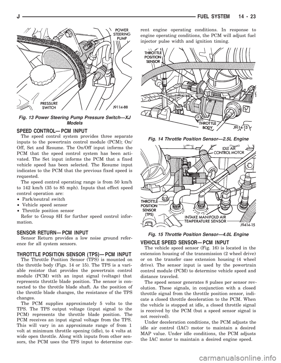
the throttle body (Figs. 14 or 15). The TPS is a vari-
able resistor that provides the powertrain control
module (PCM) with an input signal (voltage) that
represents throttle blade position. The sensor is con-
nected to the throttle blade shaft. As the position of
the throttle blade changes, the resistance of the TPS
changes.
The PCM supplies approximately 5 volts to the
TPS. The TPS output voltage (input signal to the
PCM) represents the throttle blade position. The
PCM receives an input signal voltage from the TPS.
This will vary in an approximate range of from 1
volt at minimum throttle opening (idle), to 4 volts at
wide open throttle. Along with inputs from other sen-
sors, the PCM uses the TPS input to determine cur-rent engine operating conditions. In response to
engine operating conditions, the PCM will adjust fuel
injector pulse width and ignition timing.
VEHICLE SPEED SENSORÐPCM INPUT
The vehicle speed sensor (Fig. 16) is located in the
extension housing of the transmission (2 wheel drive)
or on the transfer case extension housing (4 wheel
drive). The sensor input is used by the powertrain
control module (PCM) to determine vehicle speed and
distance traveled.
The speed sensor generates 8 pulses per sensor rev-
olution. These signals, in conjunction with a closed
throttle signal from the throttle position sensor, indi-
cate a closed throttle deceleration to the PCM. When
the vehicle is stopped at idle, a closed throttle signal
is received by the PCM (but a speed sensor signal is
not received).
Under deceleration conditions, the PCM adjusts the
idle air control (IAC) motor to maintain a desired
MAP value. Under idle conditions, the PCM adjusts
the IAC motor to maintain a desired engine speed.
Fig. 13 Power Steering Pump Pressure SwitchÐXJ
Models
Fig. 14 Throttle Position SensorÐ2.5L Engine
Fig. 15 Throttle Position SensorÐ4.0L Engine
JFUEL SYSTEM 14 - 23
Page 1021 of 1784
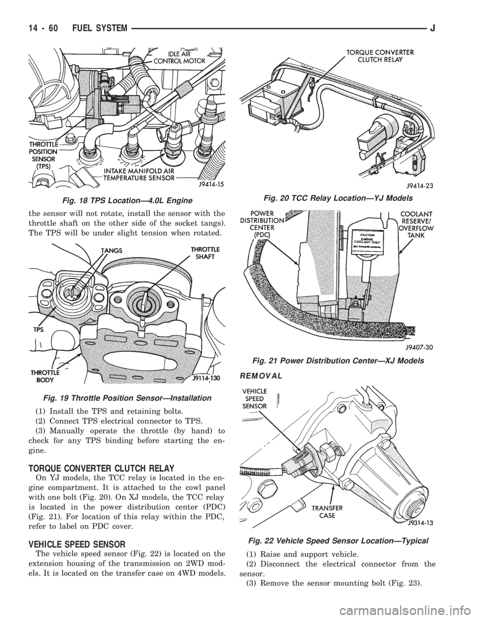
the sensor will not rotate, install the sensor with the
throttle shaft on the other side of the socket tangs).
The TPS will be under slight tension when rotated.
(1) Install the TPS and retaining bolts.
(2) Connect TPS electrical connector to TPS.
(3) Manually operate the throttle (by hand) to
check for any TPS binding before starting the en-
gine.
TORQUE CONVERTER CLUTCH RELAY
On YJ models, the TCC relay is located in the en-
gine compartment. It is attached to the cowl panel
with one bolt (Fig. 20). On XJ models, the TCC relay
is located in the power distribution center (PDC)
(Fig. 21). For location of this relay within the PDC,
refer to label on PDC cover.
VEHICLE SPEED SENSOR
The vehicle speed sensor (Fig. 22) is located on the
extension housing of the transmission on 2WD mod-
els. It is located on the transfer case on 4WD models.
REMOVAL
(1) Raise and support vehicle.
(2) Disconnect the electrical connector from the
sensor.
(3) Remove the sensor mounting bolt (Fig. 23).
Fig. 18 TPS LocationÐ4.0L Engine
Fig. 19 Throttle Position SensorÐInstallation
Fig. 20 TCC Relay LocationÐYJ Models
Fig. 21 Power Distribution CenterÐXJ Models
Fig. 22 Vehicle Speed Sensor LocationÐTypical
14 - 60 FUEL SYSTEMJ
Page 1024 of 1784
PROPELLER SHAFTS
CONTENTS
page page
GENERAL INFORMATION.................. 1
PROPELLER SHAFT REPLACEMENT......... 7
SERVICE DIAGNOSIS/PROCEDURES......... 3TORQUE SPECIFICATIONS................ 14
UNIVERSAL JOINT REPLACEMENT.......... 9
GENERAL INFORMATION
PROPELLER SHAFTS
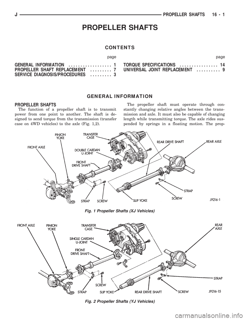
The function of a propeller shaft is to transmit
power from one point to another. The shaft is de-
signed to send torque from the transmission (transfer
case on 4WD vehicles) to the axle (Fig. 1,2).The propeller shaft must operate through con-
stantly changing relative angles between the trans-
mission and axle. It must also be capable of changing
length while transmitting torque. The axle rides sus-
pended by springs in a floating motion. The prop-
Fig. 1 Propeller Shafts (XJ Vehicles)
Fig. 2 Propeller Shafts (YJ Vehicles)
JPROPELLER SHAFTS 16 - 1