1994 JEEP CHEROKEE Transfer case
[x] Cancel search: Transfer casePage 27 of 1784
If the transfer case ATF is warm, it is accept-
able for the fluid to drip out of the fill hole. If
the fluid gushes out of the fill hole, the level is
too high.
(3) If the level is low, raise it to the bottom edge of
the fill hole with MOPAR ATF PLUS type 7176 or
an equivalent MerconŸ/Dexron IIŸ ATF.
(4) Install the fill-hole plug. Tighten the plug with
47 NIm (35 ft. lbs.) torque.
(5) Remove the support and lower the vehicle.
FLUID CHANGE
When it becomes necessary to change the ATF in a
Jeepttransfer case, use the following procedure.
(1) Raise and support the vehicle.
(2) Remove the fill-hole plug from the transfer
case.
(3) Place an appropriate container under the trans-
fer case drain-hole plug.
(4) Remove the drain-hole plug and drain the ATF
from the transfer case into the container.
Care should be exercised when disposing used
ATF after it has been drained from a transfer
case.
CAUTION: Do not over-tighten the drain and fill-hole
plugs. Over-tightening can strip the hole threads
and/or crack the aluminum housing.
(5) Install the drain-hole plug in the transfer case.
Tighten the plug with 47 NIm (35 ft. lbs.) torque.
(6) Fill the transfer case to the bottom edge of the
fill hole with MOPAR ATF PLUS type 7176 (or an
equivalent MerconŸ/Dexron IIŸ ATF).
(7) Install the fill-hole plug in the transfer case.
Tighten the plug with 47 NIm (35 ft. lbs.) torque.
(8) Remove the support and lower the vehicle.
FRONT AND REAR AXLES
RECOMMENDED MAINTENANCE
The lubricant level in axle differential housings
should be determined at the same time as the engine
oil is changed and the oil filter is replaced. Add lu-
bricant as necessary.
In addition, with normal driving conditions, the
axle lubricant should be changed after each 48
000-km (30,000-miles). With severe driving condi-
tions, after each 29 000-km (12,000-miles).
LUBRICANT SPECIFICATIONS
For normal vehicle operation, use SAE 75W-90,
API Quality Grade GL-5 gear lubricant in all Jeept
front (4WD only) and rear axles. Vehicles equipped
with a Trac-Loc rear axle also require a friction mod-
ifier additive with the gear lubricant.
When involved in trailer towing applications
use SAE 80W-140, API Quality Grade GL-5 gearlubricant in the rear axle. XJ Vehicles equipped
with a class III trailer hitch require SAE
75W-140 synthetic gear lubricant in the rear
axle.
LUBRICANT LEVEL
Determine the axle differential housing lubricant
level according to the following procedure.
(1) Raise and support the vehicle.
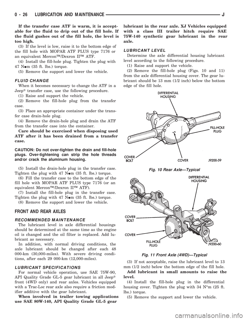
(2) Remove the fill-hole plug (Figs. 10 and 11)
from the axle differential housing cover. The gear lu-
bricant should be 13 mm (1/2 inch) below the bottom
edge of the fill hole.
(3) If not acceptable, raise the lubricant level to 13
mm (1/2 inch) below the bottom edge of the fill hole.
Add lubricant in small amounts to raise the
level.
(4) Install the fill-hole plug in the differential
housing cover. Tighten the plug with 34 NÉm (25 ft.
lbs.) torque.
(5) Remove the support and lower the vehicle.
Fig. 10 Rear AxleÐTypical
Fig. 11 Front Axle (4WD)ÐTypical
0 - 26 LUBRICATION AND MAINTENANCEJ
Page 30 of 1784
(2) Inspect the surface of hoses and tubing for heat
and mechanical damage. Hose and tubing located
close to an exhaust pipe should be given special at-
tention.
(3) Inspect the rubber hose routing to ensure that
the hoses do not contact any heat source, moving
component, etc., that would potentially cause heat or
mechanical damage.
(4) Inspect all the hose connections to ensure that
they are secure and there is no fluid leakage. Actual
dripping of hot fluid should be noted and the clamps
tightened in an attempt to stop the leakage before
replacing the hose.
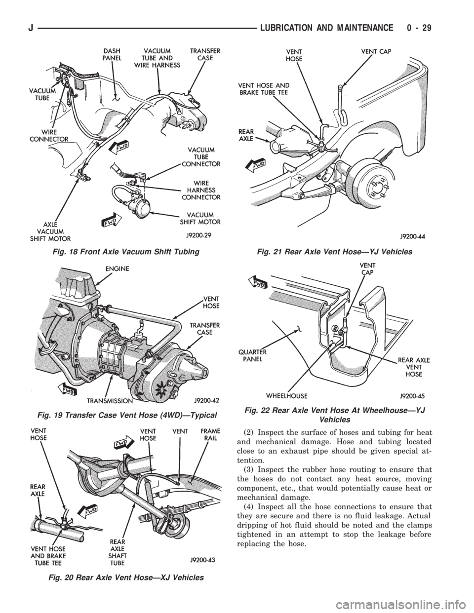
Fig. 18 Front Axle Vacuum Shift Tubing
Fig. 19 Transfer Case Vent Hose (4WD)ÐTypical
Fig. 20 Rear Axle Vent HoseÐXJ Vehicles
Fig. 21 Rear Axle Vent HoseÐYJ Vehicles
Fig. 22 Rear Axle Vent Hose At WheelhouseÐYJ
Vehicles
JLUBRICATION AND MAINTENANCE 0 - 29
Page 54 of 1784
level. Where axle bearing damage is slight, the noise
is usually not noticeable at speeds above 30 mph.
LOW SPEED KNOCK
Low speed knock is generally caused by a worn
U-joint or by worn side-gear thrust washers. A worn
pinion gear shaft bore will also cause low speed
knock.
VIBRATION
Vibration at the rear of the vehicle is usually
caused by a:
²Damaged drive shaft
²Missing drive shaft balance weight
²Worn, out-of-balance wheels
²Loose wheel lug nuts
²Worn U-joint
²Loose spring U-bolts
²Loose/broken springs
²Damaged axle shaft bearings
²Loose pinion gear nut
²Excessive pinion yoke run out
²Bent axle shaft
Check for loose or damaged front-end components
or engine/transmission mounts. These componentscan contribute to what appears to be a rear-end vi-
bration. Do not overlook engine accessories, brackets
and drive belts.
All driveline components should be examined be-
fore starting any repair.
Refer to Group 22ÐTires And Wheels for addi-
tional information involving vibration diagnosis.
DRIVELINE SNAP
A snap or clunk noise when the vehicle is shifted
into gear (or the clutch engaged), can be caused by:
²High engine idle speed
²Loose engine/transmission/transfer case mounts
²Worn U-joints
²Loose spring mounts
²Loose pinion gear nut and yoke
²Excessive ring gear backlash
²Excessive differential side gear-to-case clearance
The source of a snap or a clunk noise can be deter-
mined with the assistance of a helper. Raise the ve-
hicle on a hoist with the wheels free to rotate.
Instruct the helper to shift the transmission into
gear. Listen for the noise, a mechanics stethoscope is
helpful in isolating the source of a noise.
JFRONT SUSPENSION AND AXLE 2 - 17
Page 57 of 1784
MODEL 30 AXLE AND TUBE AXLE (2WD)
INDEX
page page
Axle Bushing Replacement................. 32
Axle Shaft Ð Cardan U-Joint................ 25
Axle Specifications....................... 46
Backlash and Contact Pattern Analysis........ 44
Cleaning/Inspection....................... 35
Differential and Pinion Measurement.......... 38
Differential Assembly...................... 36
Differential Disassembly.................... 34
Differential Installation..................... 43
Differential Removal...................... 32
Differential Shim Pack Measurement and Adjustment.42
Drive Axle Assembly ReplacementÐXJ Vehicles . 21
Drive Axle Assembly ReplacementÐYJ Vehicles . 21Final Assembly.......................... 44
Hub Bearing and Axle Shaft................ 24
Information............................. 20
Inner Axle Shaft Oil Seal Replacement........ 33
Lubricant Change........................ 22
Lubricant Specifications.................... 20
Pinion Gear Assembly/Installation............ 40
Pinion Gear Depth Information.............. 37
Pinion Removal/Disassembly................ 34
Pinion Seal Replacement.................. 23
Steering Knuckle and Ball Studs............. 30
Vacuum Disconnect Axle Ð YJ Vehicles....... 26
INFORMATION
The housing for Model 30 front axles consists of an
iron center casting (differential housing) with axle
shaft tubes extending from either side. The tubes are
pressed into and welded to the differential housing to
form a one-piece axle housing.
The integral type housing, hypoid gear design has
the centerline of the pinion set above the centerline
of the ring gear.
The axle has a fitting for a vent hose used to re-
lieve internal pressure caused by lubricant vaporiza-
tion and internal expansion.
The axles are equipped with semi-floating axle
shafts, meaning that loads are supported by the hub
bearings. The axle shafts are retained by nuts at the
hub bearings. The hub bearings are bolted to the
steering knuckle at the outboard end of the axle tube
yoke. The hub bearings are serviced as an assembly.
The axles are equipped with ABS brake sensors.
The sensors are attached to the knuckle assemblies
and tone rings are pressed on the axle shaft.Use
care when removing axle shafts as NOT to dam-
age the tone wheel or the sensor.
The stamped steel cover provides a means for in-
spection and servicing the differential.
The Model 30 axle has the assembly part number
and gear ratio listed on a tag. The tag is attached to
the housing cover. Build date identification codes are
stamped on the axle shaft tube cover side.
The differential case is a one-piece design. The dif-
ferential pinion mate shaft is retained with a roll
pin. Differential bearing preload and ring gear back-
lash is adjusted by the use of shims (select thick-
ness). The shims are located between the differential
bearing cones and case. Pinion bearing preload is set
and maintained by the use of collapsible spacer.
PINION GEAR DEPTH MEASUREMENT WITH
PINION GAUGE SET 6774, Pinion Block 6733 and
Dial Indicator C-3339 is performed when;²Axle/differential housing is being replaced
²Original pinion depth shim pack is lost or mis-
placed
²Replacing the differential case
²Original differential bearing shim pack is lost or
misplaced
COMMAND-TRACÐYJ VEHICLES
The Command-Trac system is a vacuum disconnect
axle. The system has a two-piece axle shaft coupled
together by a shift collar. For two-wheel drive oper-
ation, the vacuum motor and shift fork disengages
the axle shaft splines. For four-wheel drive opera-
tion, the vacuum motor and shift fork engages the
splines.
SELEC-TRACÐXJ VEHICLES
The Selec-Trac system is a non-disconnect axle.
Shifting from two-wheel to four-wheel drive is at the
transfer case.
For XJ vehicles equipped withSelec-Tracand
ABS brake system, refer to Group 5ÐBrakes for ad-
ditional service information.
LUBRICANT SPECIFICATIONS
Multi-purpose, hypoid gear lubricant should be
used for Model 30 axles. The lubricant should have
MIL-L-2105C and API GL 5 quality specifications.
MOPARtHypoid Gear Lubricant conforms to both of
these specifications.
²The factory fill for the Model 30 axle is SAE 75W
gear lubricant.Do not use heavier weight lubri-
cant, this will cause axle engagement difficulties.
²The factory installed lubricant quantity for the
NON-DISCONNECT TYPE AXLE is 5061 fluid oz..
²The factory installed lubricant quantity for the
VACUUM-DISCONNECT TYPE AXLE is 5661 fluid
oz..
2 - 20 FRONT SUSPENSION AND AXLEJ
Page 63 of 1784
(3) Place the socket (driver) against one bearing
cap. Position the yoke with the socket wrench in a
vise.
(4) Compress the vise to force the bearing caps into
the yoke. Force the caps enough to install the retain-
ing clips.
(5) Install the bearing cap retaining clips.
(6) Install the axle shaft, refer to Hub Bearing and
Axle Shaft installation.
VACUUM DISCONNECT AXLE Ð YJ VEHICLES
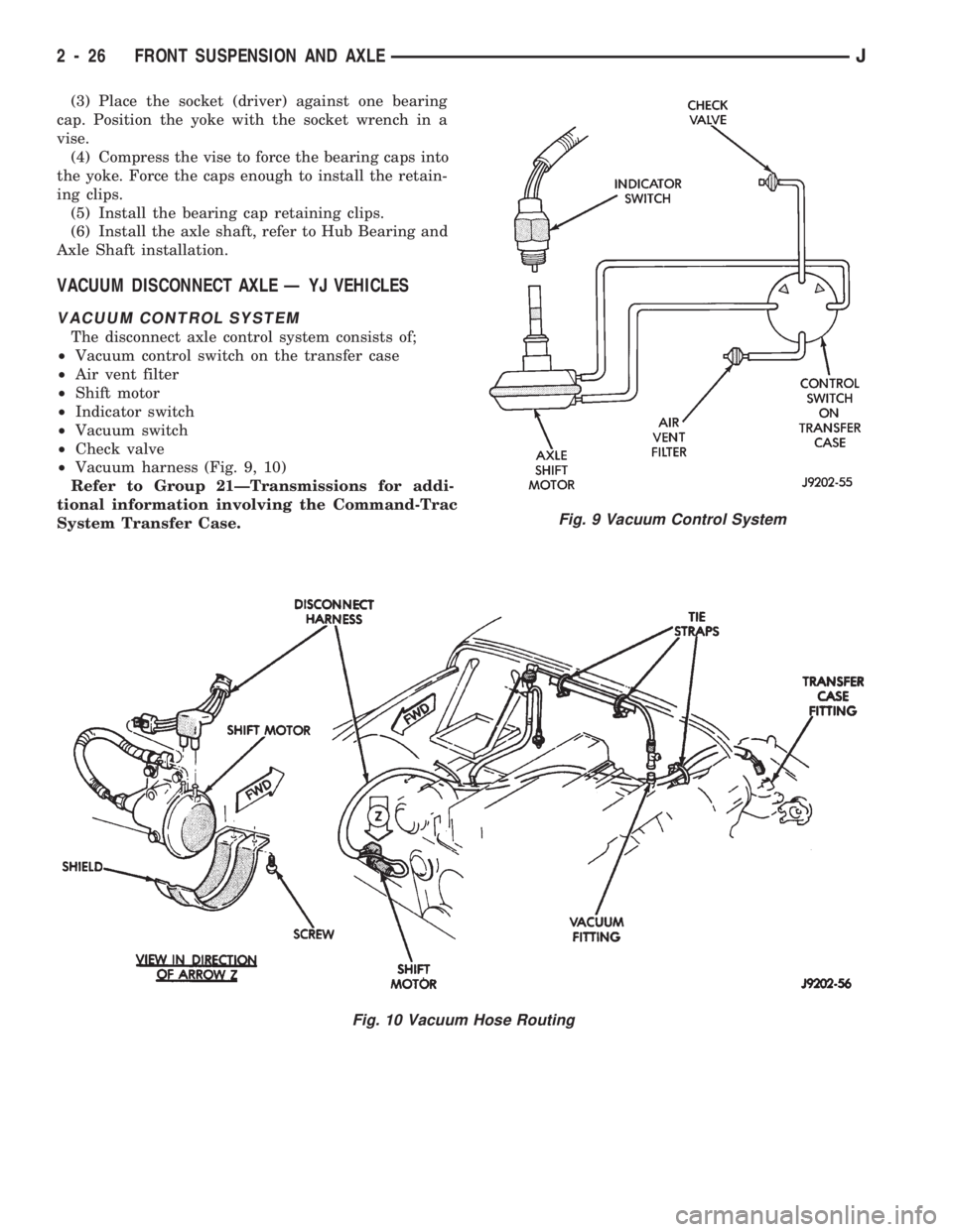
VACUUM CONTROL SYSTEM
The disconnect axle control system consists of;
²Vacuum control switch on the transfer case
²Air vent filter
²Shift motor
²Indicator switch
²Vacuum switch
²Check valve
²Vacuum harness (Fig. 9, 10)
Refer to Group 21ÐTransmissions for addi-
tional information involving the Command-Trac
System Transfer Case.
Fig. 9 Vacuum Control System
Fig. 10 Vacuum Hose Routing
2 - 26 FRONT SUSPENSION AND AXLEJ
Page 81 of 1784
BACKLASH AND CONTACT PATTERN ANALYSIS
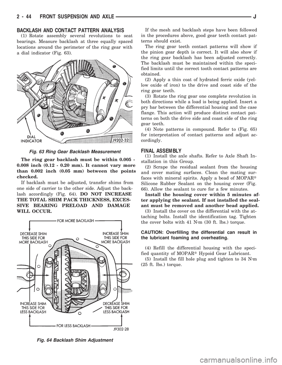
(1) Rotate assembly several revolutions to seat
bearings. Measure backlash at three equally spaced
locations around the perimeter of the ring gear with
a dial indicator (Fig. 63).
The ring gear backlash must be within 0.005 -
0.008 inch (0.12 - 0.20 mm). It cannot vary more
than 0.002 inch (0.05 mm) between the points
checked.
If backlash must be adjusted, transfer shims from
one side of carrier to the other side. Adjust the back-
lash accordingly (Fig. 64).DO NOT INCREASE
THE TOTAL SHIM PACK THICKNESS, EXCES-
SIVE BEARING PRELOAD AND DAMAGE
WILL OCCUR.If the mesh and backlash steps have been followed
in the procedures above, good gear teeth contact pat-
terns should exist.
The ring gear teeth contact patterns will show if
the pinion gear depth is correct. It will also show if
the ring gear backlash has been adjusted correctly.
The backlash must be maintained within the speci-
fied limits until the correct tooth contact patterns are
obtained.
(2) Apply a thin coat of hydrated ferric oxide (yel-
low oxide of iron) to the drive and coast side of the
ring gear teeth.
(3) Rotate the ring gear one complete revolution in
both directions while a load is being applied. Insert a
pry bar between the differential housing and the case
flange. This action will produce distinct contact pat-
terns on both the drive side and coast side of the ring
gear teeth.
(4) Note patterns in compound. Refer to (Fig. 65)
for interpretation of contact patterns and adjust ac-
cordingly.
FINAL ASSEMBLY
(1) Install the axle shafts. Refer to Axle Shaft In-
stallation in this Group.
(2) Scrape the residual sealant from the housing
and cover mating surfaces. Clean the mating sur-
faces with mineral spirits. Apply a bead of MOPARt
Silicone Rubber Sealant on the housing cover (Fig.
66). Allow the sealant to cure for a few minutes.
Install the housing cover within 5 minutes af-
ter applying the sealant. If not installed the seal-
ant must be removed and another bead applied.
(3) Install the cover on the differential with the at-
taching bolts. Install the identification tag. Tighten
the cover bolts with 41 Nzm (30 ft. lbs.) torque.
CAUTION: Overfilling the differential can result in
the lubricant foaming and overheating.
(4) Refill the differential housing with the speci-
fied quantity of MOPARtHypoid Gear Lubricant.
(5) Install the fill hole plug and tighten to 34 Nzm
(25 ft. lbs.) torque.Fig. 63 Ring Gear Backlash Measurement
Fig. 64 Backlash Shim Adjustment
2 - 44 FRONT SUSPENSION AND AXLEJ
Page 108 of 1784
SPEED CONTROLÐPCM INPUT
The speed control system provides three separate
inputs to the powertrain control module (PCM); On/
Off, Set and Resume. The On/Off input informs the
PCM that the speed control system has been acti-
vated. The Set input informs the PCM that a fixed
vehicle speed has been selected. The Resume input
indicates to the PCM that the previous fixed speed is
requested.
The speed control operating range is from 50 km/h
to 142 km/h (35 to 85 mph). Inputs that effect speed
control operation are:
²Park/neutral switch
²Vehicle speed sensor
²Throttle position sensor
Refer to Group 8H for further speed control infor-
mation.
SENSOR RETURNÐPCM INPUT
Sensor Return provides a low noise ground refer-
ence for all system sensors.
THROTTLE POSITION SENSOR (TPS)ÐPCM INPUT
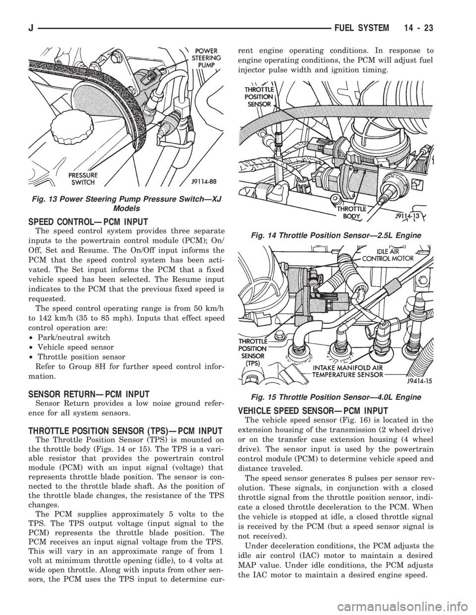
The Throttle Position Sensor (TPS) is mounted on
the throttle body (Figs. 14 or 15). The TPS is a vari-
able resistor that provides the powertrain control
module (PCM) with an input signal (voltage) that
represents throttle blade position. The sensor is con-
nected to the throttle blade shaft. As the position of
the throttle blade changes, the resistance of the TPS
changes.
The PCM supplies approximately 5 volts to the
TPS. The TPS output voltage (input signal to the
PCM) represents the throttle blade position. The
PCM receives an input signal voltage from the TPS.
This will vary in an approximate range of from 1
volt at minimum throttle opening (idle), to 4 volts at
wide open throttle. Along with inputs from other sen-
sors, the PCM uses the TPS input to determine cur-rent engine operating conditions. In response to
engine operating conditions, the PCM will adjust fuel
injector pulse width and ignition timing.
VEHICLE SPEED SENSORÐPCM INPUT
The vehicle speed sensor (Fig. 16) is located in the
extension housing of the transmission (2 wheel drive)
or on the transfer case extension housing (4 wheel
drive). The sensor input is used by the powertrain
control module (PCM) to determine vehicle speed and
distance traveled.
The speed sensor generates 8 pulses per sensor rev-
olution. These signals, in conjunction with a closed
throttle signal from the throttle position sensor, indi-
cate a closed throttle deceleration to the PCM. When
the vehicle is stopped at idle, a closed throttle signal
is received by the PCM (but a speed sensor signal is
not received).
Under deceleration conditions, the PCM adjusts the
idle air control (IAC) motor to maintain a desired
MAP value. Under idle conditions, the PCM adjusts
the IAC motor to maintain a desired engine speed.
Fig. 13 Power Steering Pump Pressure SwitchÐXJ
Models
Fig. 14 Throttle Position SensorÐ2.5L Engine
Fig. 15 Throttle Position SensorÐ4.0L Engine
JFUEL SYSTEM 14 - 23
Page 145 of 1784
the sensor will not rotate, install the sensor with the
throttle shaft on the other side of the socket tangs).
The TPS will be under slight tension when rotated.
(1) Install the TPS and retaining bolts.
(2) Connect TPS electrical connector to TPS.
(3) Manually operate the throttle (by hand) to
check for any TPS binding before starting the en-
gine.
TORQUE CONVERTER CLUTCH RELAY
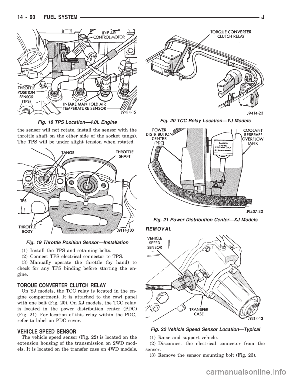
On YJ models, the TCC relay is located in the en-
gine compartment. It is attached to the cowl panel
with one bolt (Fig. 20). On XJ models, the TCC relay
is located in the power distribution center (PDC)
(Fig. 21). For location of this relay within the PDC,
refer to label on PDC cover.
VEHICLE SPEED SENSOR
The vehicle speed sensor (Fig. 22) is located on the
extension housing of the transmission on 2WD mod-
els. It is located on the transfer case on 4WD models.
REMOVAL
(1) Raise and support vehicle.
(2) Disconnect the electrical connector from the
sensor.
(3) Remove the sensor mounting bolt (Fig. 23).
Fig. 18 TPS LocationÐ4.0L Engine
Fig. 19 Throttle Position SensorÐInstallation
Fig. 20 TCC Relay LocationÐYJ Models
Fig. 21 Power Distribution CenterÐXJ Models
Fig. 22 Vehicle Speed Sensor LocationÐTypical
14 - 60 FUEL SYSTEMJ