Page 1398 of 1784
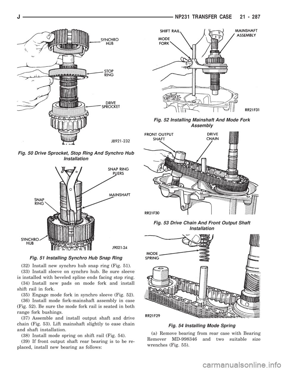
(32) Install new synchro hub snap ring (Fig. 51).
(33) Install sleeve on synchro hub. Be sure sleeve
is installed with beveled spline ends facing stop ring.
(34) Install new pads on mode fork and install
shift rail in fork.
(35) Engage mode fork in synchro sleeve (Fig. 52).
(36) Install mode fork-mainshaft assembly in case
(Fig. 52). Be sure the mode fork rail is seated in both
range fork bushings.
(37) Assemble and install output shaft and drive
chain (Fig. 53). Lift mainshaft slightly to ease chain
and shaft installation.
(38) Install mode spring on shift rail (Fig. 54).
(39) If front output shaft rear bearing is to be re-
placed, install new bearing as follows:(a) Remove bearing from rear case with Bearing
Remover MD-998346 and two suitable size
wrenches (Fig. 55).
Fig. 51 Installing Synchro Hub Snap Ring
Fig. 50 Drive Sprocket, Stop Ring And Synchro Hub
Installation
Fig. 52 Installing Mainshaft And Mode Fork
Assembly
Fig. 53 Drive Chain And Front Output Shaft
Installation
Fig. 54 Installing Mode Spring
JNP231 TRANSFER CASE 21 - 287
Page 1399 of 1784
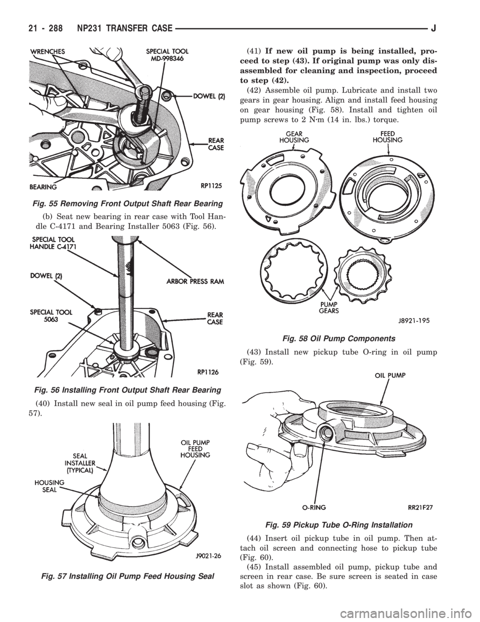
(b) Seat new bearing in rear case with Tool Han-
dle C-4171 and Bearing Installer 5063 (Fig. 56).
(40) Install new seal in oil pump feed housing (Fig.
57).(41)If new oil pump is being installed, pro-
ceed to step (43). If original pump was only dis-
assembled for cleaning and inspection, proceed
to step (42).
(42) Assemble oil pump. Lubricate and install two
gears in gear housing. Align and install feed housing
on gear housing (Fig. 58). Install and tighten oil
pump screws to 2 Nzm (14 in. lbs.) torque.
(43) Install new pickup tube O-ring in oil pump
(Fig. 59).
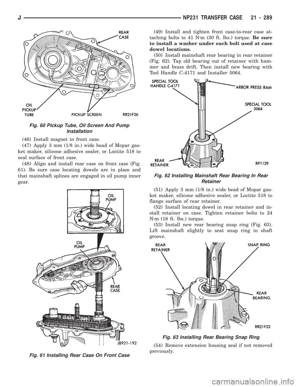
(44) Insert oil pickup tube in oil pump. Then at-
tach oil screen and connecting hose to pickup tube
(Fig. 60).
(45) Install assembled oil pump, pickup tube and
screen in rear case. Be sure screen is seated in case
slot as shown (Fig. 60).
Fig. 55 Removing Front Output Shaft Rear Bearing
Fig. 56 Installing Front Output Shaft Rear Bearing
Fig. 57 Installing Oil Pump Feed Housing Seal
Fig. 58 Oil Pump Components
Fig. 59 Pickup Tube O-Ring Installation
21 - 288 NP231 TRANSFER CASEJ
Page 1400 of 1784
(46) Install magnet in front case.
(47) Apply 3 mm (1/8 in.) wide bead of Mopar gas-
ket maker, silicone adhesive sealer, or Loctite 518 to
seal surface of front case.
(48) Align and install rear case on front case (Fig.
61). Be sure case locating dowels are in place and
that mainshaft splines are engaged in oil pump inner
gear.(49) Install and tighten front case-to-rear case at-
taching bolts to 41 Nzm (30 ft. lbs.) torque.Be sure
to install a washer under each bolt used at case
dowel locations.
(50) Install mainshaft rear bearing in rear retainer
(Fig. 62). Tap old bearing out of retainer with ham-
mer and brass drift. Then install new bearing with
Tool Handle C-4171 and Installer 5064.
(51) Apply 3 mm (1/8 in.) wide bead of Mopar gas-
ket maker, silicone adhesive sealer, or Loctite 518 to
flange surface of rear retainer.
(52) Install locating dowel in rear retainer and in-
stall retainer on case. Tighten retainer bolts to 24
Nzm (18 ft. lbs.) torque.
(53) Install new rear bearing snap ring (Fig. 63).
Lift mainshaft slightly to seat snap ring in shaft
groove.
(54) Remove extension housing seal if not removed
previously.
Fig. 60 Pickup Tube, Oil Screen And Pump
Installation
Fig. 61 Installing Rear Case On Front Case
Fig. 62 Installing Mainshaft Rear Bearing In Rear
Retainer
Fig. 63 Installing Rear Bearing Snap Ring
JNP231 TRANSFER CASE 21 - 289
Page 1401 of 1784
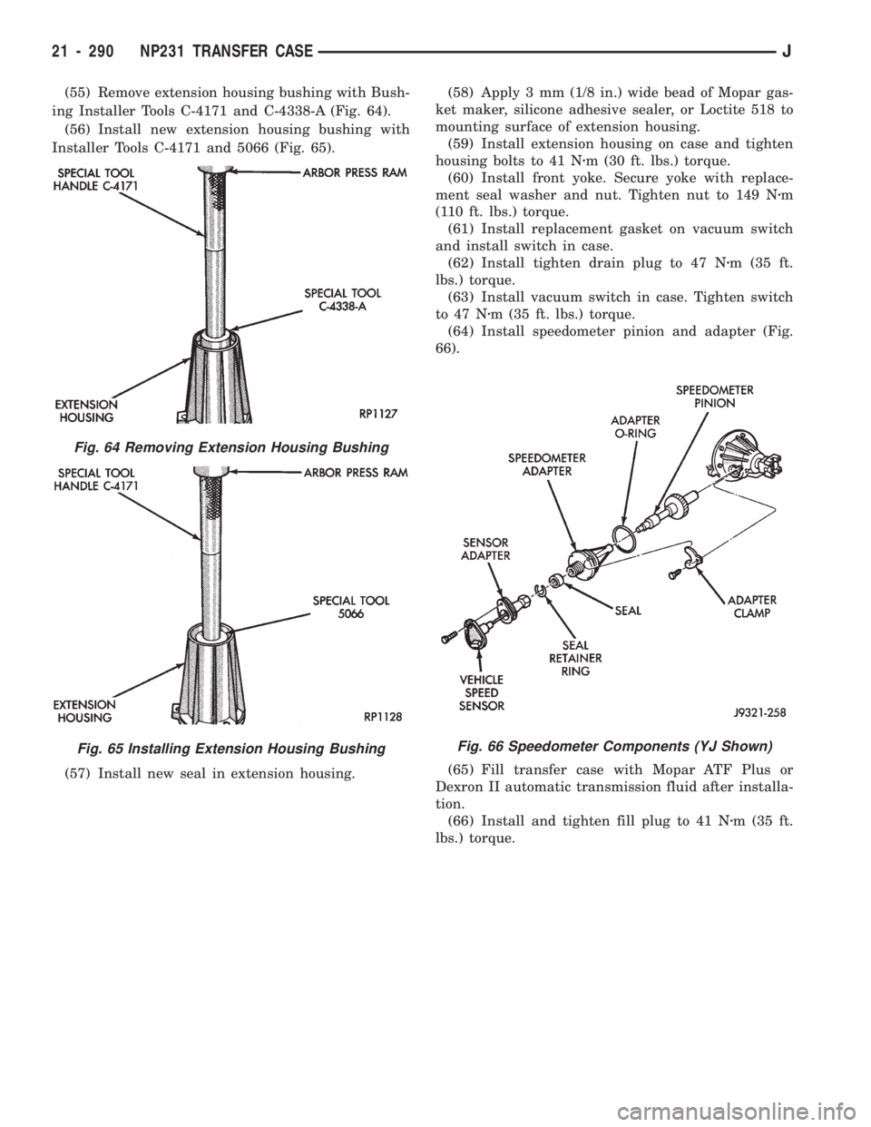
(55) Remove extension housing bushing with Bush-
ing Installer Tools C-4171 and C-4338-A (Fig. 64).
(56) Install new extension housing bushing with
Installer Tools C-4171 and 5066 (Fig. 65).
(57) Install new seal in extension housing.(58) Apply 3 mm (1/8 in.) wide bead of Mopar gas-
ket maker, silicone adhesive sealer, or Loctite 518 to
mounting surface of extension housing.
(59) Install extension housing on case and tighten
housing bolts to 41 Nzm (30 ft. lbs.) torque.
(60) Install front yoke. Secure yoke with replace-
ment seal washer and nut. Tighten nut to 149 Nzm
(110 ft. lbs.) torque.
(61) Install replacement gasket on vacuum switch
and install switch in case.
(62) Install tighten drain plug to 47 Nzm (35 ft.
lbs.) torque.
(63) Install vacuum switch in case. Tighten switch
to 47 Nzm (35 ft. lbs.) torque.
(64) Install speedometer pinion and adapter (Fig.
66).
(65) Fill transfer case with Mopar ATF Plus or
Dexron II automatic transmission fluid after installa-
tion.
(66) Install and tighten fill plug to 41 Nzm (35 ft.
lbs.) torque.
Fig. 64 Removing Extension Housing Bushing
Fig. 65 Installing Extension Housing BushingFig. 66 Speedometer Components (YJ Shown)
21 - 290 NP231 TRANSFER CASEJ
Page 1402 of 1784
NP231 TRANSFER CASE
JNP231 TRANSFER CASE 21 - 291
Page 1403 of 1784
LEGEND FOR NP231 TRANSFER CASE
21 - 292 NP231 TRANSFER CASEJ
Page 1404 of 1784
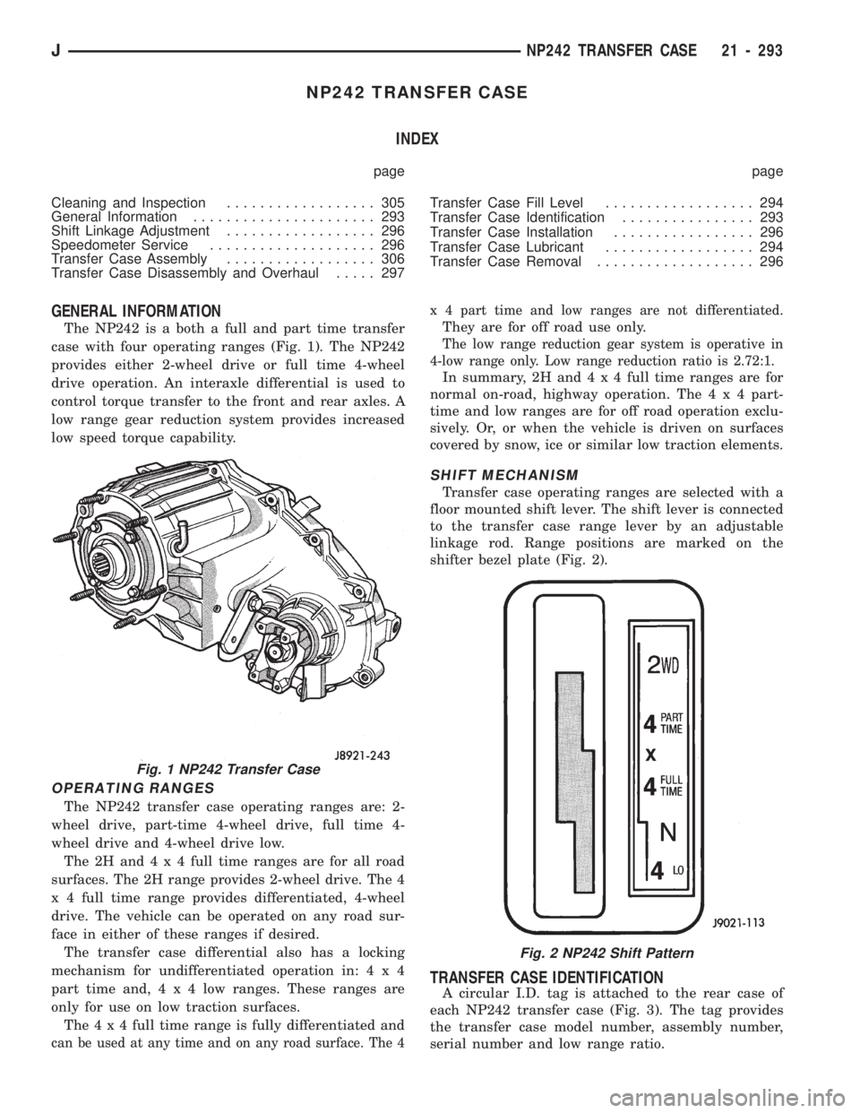
NP242 TRANSFER CASE
INDEX
page page
Cleaning and Inspection.................. 305
General Information...................... 293
Shift Linkage Adjustment.................. 296
Speedometer Service.................... 296
Transfer Case Assembly.................. 306
Transfer Case Disassembly and Overhaul..... 297Transfer Case Fill Level.................. 294
Transfer Case Identification................ 293
Transfer Case Installation................. 296
Transfer Case Lubricant.................. 294
Transfer Case Removal................... 296
GENERAL INFORMATION
The NP242 is a both a full and part time transfer
case with four operating ranges (Fig. 1). The NP242
provides either 2-wheel drive or full time 4-wheel
drive operation. An interaxle differential is used to
control torque transfer to the front and rear axles. A
low range gear reduction system provides increased
low speed torque capability.
OPERATING RANGES
The NP242 transfer case operating ranges are: 2-
wheel drive, part-time 4-wheel drive, full time 4-
wheel drive and 4-wheel drive low.
The2Hand4x4full time ranges are for all road
surfaces. The 2H range provides 2-wheel drive. The 4
x 4 full time range provides differentiated, 4-wheel
drive. The vehicle can be operated on any road sur-
face in either of these ranges if desired.
The transfer case differential also has a locking
mechanism for undifferentiated operation in:4x4
part time and,4x4lowranges. These ranges are
only for use on low traction surfaces.
The4x4full time range is fully differentiated and
can be used at any time and on any road surface. The 4x 4 part time and low ranges are not differentiated.
They are for off road use only.
The low range reduction gear system is operative in
4-low range only. Low range reduction ratio is 2.72:1.
In summary, 2H and4x4full time ranges are for
normal on-road, highway operation. The4x4part-
time and low ranges are for off road operation exclu-
sively. Or, or when the vehicle is driven on surfaces
covered by snow, ice or similar low traction elements.
SHIFT MECHANISM
Transfer case operating ranges are selected with a
floor mounted shift lever. The shift lever is connected
to the transfer case range lever by an adjustable
linkage rod. Range positions are marked on the
shifter bezel plate (Fig. 2).
TRANSFER CASE IDENTIFICATION
A circular I.D. tag is attached to the rear case of
each NP242 transfer case (Fig. 3). The tag provides
the transfer case model number, assembly number,
serial number and low range ratio.
Fig. 1 NP242 Transfer Case
Fig. 2 NP242 Shift Pattern
JNP242 TRANSFER CASE 21 - 293
Page 1405 of 1784
The transfer case serial number also represents the
date of build. For example, a serial number of 10-
5-91 would represent October 5, 1991.
TRANSFER CASE LUBRICANT
Recommended fluid for the NP242 transfer case is
Mopar Dexron II, or ATF Plus, Type 7176 automatic
transmission fluid.
Lubricant capacity of the Model 242 transfer case
is: 1.4 liters (1.48 qts.).
TRANSFER CASE FILL LEVEL
Correct fill level for the NP242 transfer case is to
the bottom edge of the fill plug hole.
Fig. 3 Transfer Case I.D. Tag
21 - 294 NP242 TRANSFER CASEJ