1993 DODGE TRUCK check engine
[x] Cancel search: check enginePage 317 of 1502
7
- 4S
COOLING
SYSTEM
•
PULLEY BOLT IDLER
iUlLTPULLEY-
TENSIONER
MOUNTING
BOLT TENSIONER
ASSEMBLY
TENSIONER \
rULLC,\
, / ^ J9307-64 ,
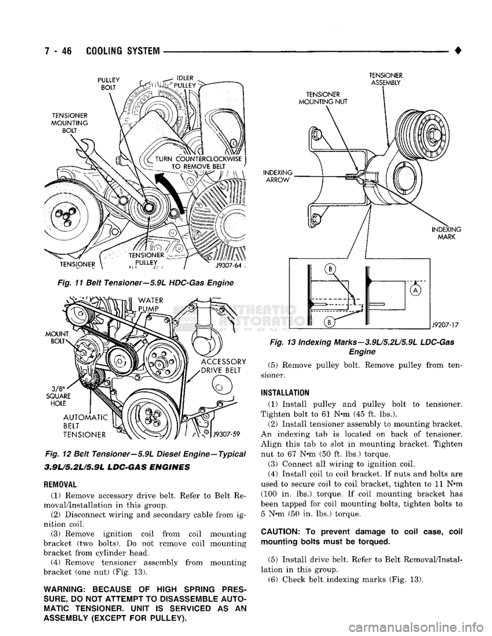
Fig.
11 Beit Tensioner—5.9L
HDC-Gas
Engine
MOUNT.
BOLT
3/8
SQUARE HOLE
ACCESSORY
DRIVE
BELT AUTOMATIC
BELT
TENSIONER
J9307-59
Fig.
12 Belt Tensioner—5.9L
Diesel
Engine—Typical
3MLm.2Lm.9L
LDG°GA8
ENGINES
REMOVAL
(1) Remove accessory drive belt. Refer to Belt Re
moval/Installation in this group. (2) Disconnect wiring and secondary cable from ig
nition coil.
(3) Remove ignition coil from coil mounting
bracket (two bolts). Do not remove coil mounting
bracket from cylinder head. (4) Remove tensioner assembly from mounting
bracket (one nut) (Fig. 13).
WARNING: BECAUSE
OF
HIGH
SPRING
PRES
SURE,
DO
NOT ATTEMPT
TO
DISASSEMBLE
AUTO
MATIC
TENSIONER.
UNIT
IS
SERVICED
AS AN
ASSEMBLY
(EXCEPT
FOR
PULLEY).
TENSIONER
MOUNTING NUT
INDEXING ARROW
INDEXING MARK
J9207-17
Fig.
13 indexing Marks-3.9L/5.2L/5.9L
LDC-Gas
Engine
(5) Remove pulley bolt. Remove pulley from ten
sioner.
INSTALLATION
(1) Install pulley and pulley bolt to tensioner.
Tighten bolt to 61 Nnn (45 ft. lbs.).
(2) Install tensioner assembly to mounting bracket.
An indexing tab is located on back of tensioner.
Align this tab to slot in mounting bracket. Tighten nut to 67 Nnn (50 ft. lbs.) torque.
(3) Connect all wiring to ignition coil. (4) Install coil to coil bracket. If nuts and bolts are
used to secure coil to coil bracket, tighten to 11 Nnn (100 in. lbs.) torque. If coil mounting bracket has
been tapped for coil mounting bolts, tighten bolts to 5 Nnn (50 in. lbs.) torque.
CAUTION:
To
prevent damage
to
coil case, coil mounting bolts must
be
torqued.
(5) Install drive belt. Refer to Belt Removal/Instal
lation in this group. (6) Check belt indexing marks (Fig. 13).
Page 320 of 1502
SPECIFICATIONS
GENERAL
INFORMATION
The following specifications are published from the
latest information available at the time of publica
tion. If anything differs between the specifica
tions found on the Vehicle Emission Control
Information (VECI) label and the following spec
ifications, use specifications on VECI label. The
VECI label is located in the engine compartment.
DRIVE
BELT
TENSION
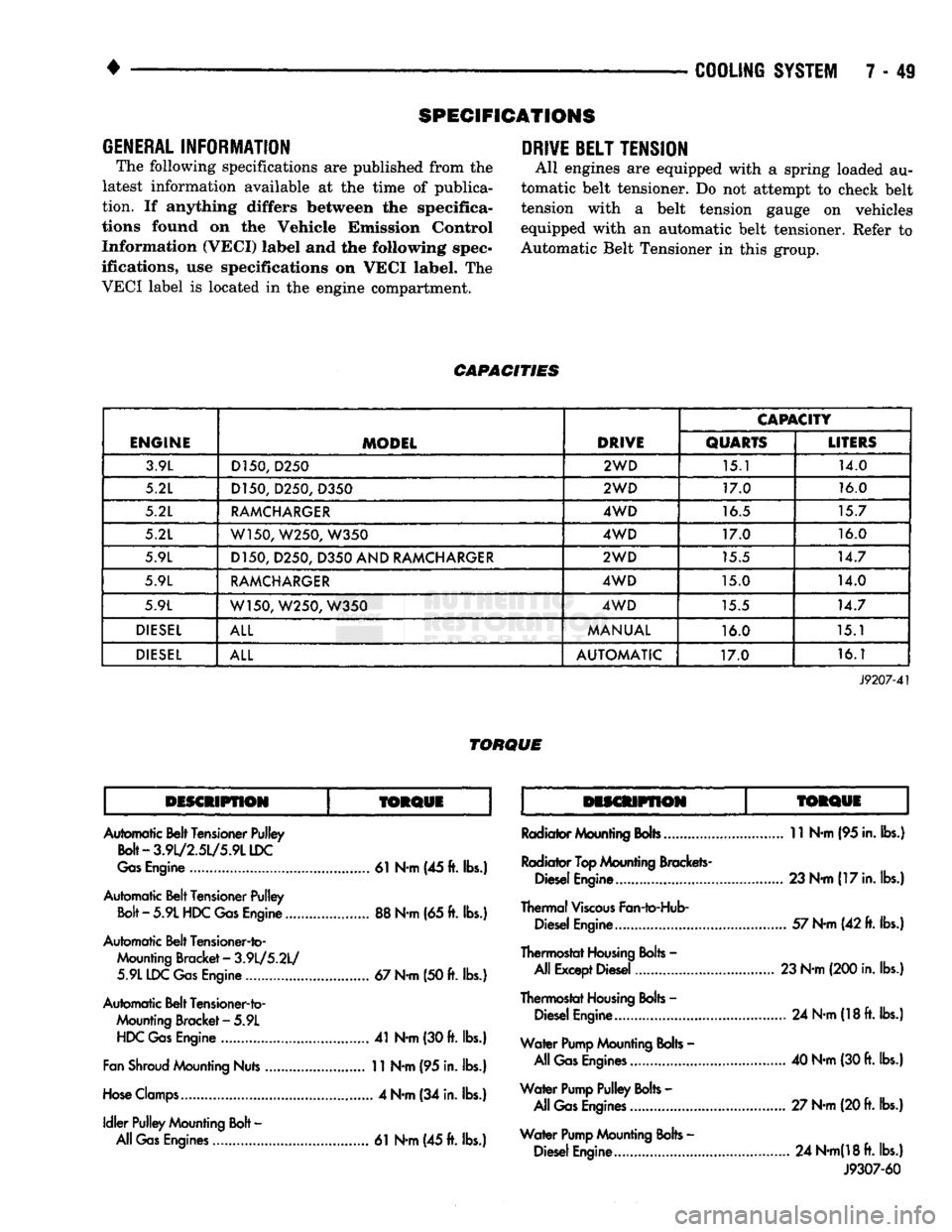
All engines are equipped with a spring loaded au
tomatic belt tensioner. Do not attempt to check belt
tension with a belt tension gauge on vehicles
equipped with an automatic belt tensioner. Refer to
Automatic Belt Tensioner in this group.
CAPACITIES
ENGINE
MODEL
DRIVE
CAPACITY
ENGINE
MODEL
DRIVE
QUARTS
LITERS
3.9L D150,
D250
2WD
15.1 14.0
5.2L D150, D250,
D350
2WD
17.0 16.0
5.2L
RAMCHARGER
4WD
16.5 15.7
5.2L W150, W250,
W350
4WD
17.0 16.0
5.9L D150, D250,
D350
AND
RAMCHARGER
2WD
15.5 14.7
5.9L
RAMCHARGER
4WD
15.0 14.0
5.9L W150, W250,
W350
4WD
15.5 14.7
DIESEL
ALL
MANUAL
16.0 15.1
DIESEL
ALL
AUTOMATIC
17.0 16.1
J9207-41
TORQUE
DISCMPflON
TORQUE
TORQUi
Automatic Belt Tensioner Pulley
Bolt-3.9l/2.5L/5.9LLDC
Gas
Engine
61
N-m (45
ft.
lbs.)
Automatic Belt Tensioner Pulley
Bolt
-
5.9L
HDC
Gas
Engine
88
N-m
(65
ft.
lbs.)
Automatic Belt Tensioner-to- Mounting Bracket
-
3.9L/5.2L/ 5.9L IDC
Gas
Engine
67
N-m
(50
ft.
lbs.)
Automatic Belt Tensioner-to- Mounting Bracket
-
5.9L
HDC
Gas
Engine
41
N-m
(30
ft.
lbs.)
Fan
Shroud
Mounting Nuts
11
N-m
(95
in. lbs.)
Hose
Clamps
4
N-m
(34
in. lbs.)
Idler
Pulley Mounting
Bolt
-
All
Gas
Engines
61
N-m
(45
ft.
lbs.)
Radiator Mounting
Bobs
11
N-m
(95
in. lbs.)
Radiator
Top
Mounting Brackets- Diesel Engine...... 23 N-m
(17
in. lbs.)
Thermal
Viscous
Fan-to-Hub- Diesel Engine
57
N-m
(42
ft.
lbs.)
Thermostat
Housing
Bolts
-
All Except Diesel 23 N-m (200 in. lbs.)
Thermostat
Housing
Bolts
-
Diesel Engine
24
N-m
(18
ft.
lbs.)
Water
Pump
Mounting
Bolts
-
All
Gas
Engines
40
N-m
(30
ft.
lbs.)
Water
Pump
Pulley
Bolts
-
All
Gas
Engines
27 N-m (20
ft.
lbs.)
Water
Pump
Mounting
Bolts
-
Diesel Engine
24
N-m(18ft.
lbs.) J9307-60
Page 333 of 1502
8A
- 12
ELECTRICAL
•
ENGINE
STARTER
RELAY
STARTER RELAY CONNECTIONS
GROUND SOLENOID (85) TERMINAL
(87) J928B-1
RELAY OPERATION/TESTING
OPERATION
• The Battery terminal is connected to battery volt
age (B +
)
at all times.
• The Solenoid terminal is connected to the battery
terminal in the energized position which supplies
battery voltage to the operated device. • The Ignition terminal is connected to the electromag
net and usually connected to a switched power source.
• The Ground terminal is connected to the electro
magnet and is usually grounded by a switch or PCM.
TESTING
• Resistance value between the ground and ignition
terminals (electromagnet) is
75
±5 ohms for resistor
relays and 86±5 ohms for diode relays.
• Connect a battery to the ignition terminal and
connect ground to the ground terminal. There should
be continuity between the battery and solenoid ter minals (contact closed).
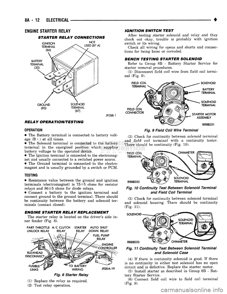
ENGINE STARTER RELAY REPLACEMENT The starter relay is located on the driver's side in
ner fender (Fig. 8).
PART THROTTLE
A/C
CLUTCH STARTER AUTO SHUT
UNLOCK RELAY RELAY RELAY DOWN RELAY
Fig.
8
Starter
Relay
(1) Replace the relay as required.
(2) Test relay operation. IGNITION SWITCH TEST
After testing starter solenoid and relay and they
check out okay, trouble is probably with ignition
switch or its wiring. Check all wiring for opens and shorts and connec
tions for being loose or corroded.
BENCH TESTING STARTER SOLENOID Refer to Group 8B - Battery Starter Service for
starter removal procedures. (1) Disconnect field coil wire from field coil termi
nal (Fig. 9).
Fig.
9 Field
Coil
Wire
Terminal
(2) Check for continuity between solenoid terminal
and field coil terminal with a continuity tester.
There should be continuity (Fig. 10).
Fig.
10 Continuity Test Between
Solenoid
Terminal
and
Field
Coil
Terminal
(3) Check for continuity between solenoid terminal
and solenoid housing. There should be continuity
(Fig. 11).
SOLENOID
RR8BD33 Fig.
11 Continuity Test Between
Solenoid
Terminal
and Solenoid Case
(4) If there is continuity solenoid is good. If there
is no continuity in either test solenoid has an open
circuit and is defective. Replace the starter motor. (5) Install starter as described in Group 8B - Bat
tery Starter Service. (6) Connect field coil wire to field coil terminal
(Fig. 9).
Page 334 of 1502
•
ELECTRICAL
8A - 13 GENERATOR TEST PROCEDURES ON
VEHICLE
INDEX
page
Current
Output
Test
......................
14
Diagnostic Procedures
13
General
Information
13
Generator
Output
Wire Resistance Test
.......
13
page
How
to
Use
Malfunction
Indicator
(Check Engine) Lamp
for
Fault
Codes
17
Operational Check
with
Voltmeter
............
13
Using
On-Board Diagnostic System
15
GENERAL
INFORMATION
The generator
is
belt-driven
by the
engine.
All en
gines
use
serpentine drive. The amount
of DC
current produced
by the
gener
ator
is
controlled
by the
Powertrain Control Module (PCM).
All vehicles
are
equipped with
On
Board Diagnos
tics (OBD).
All OBD
sensing systems
are
monitored
by
the PCM. The PCM
will store
in
electronic mem ory
any
detectable failure within
the
monitored cir
cuits.
Refer
to
USING ON-BOARD DIAGNOSTIC SYSTEM
in
this group
for
more information.
OPERATIONAL CHECK
WITH
VOLTMETER
When
the
ignition switch
is
turned
to the RUN po
sition, battery potential will register
on the
voltme
ter. During engine cranking
a
lower voltage will appear
on the
meter. With
the
engine running,
a
voltage reading higher than
the
first reading (igni
tion
in RUN)
should register.
DIAGNOSTIC PROCEDURES
If
the
indicator does
not
operate properly,
or if an
undercharged
or
overcharged battery condition
oc
curs,
the
following procedures
may be
used
to
diag
nose
the
charging system. Remember that
an
undercharged battery
is
often
caused
by:
• accessories being left
on
overnight
•
or by a
defective switch which allows
a
bulb, such
as a
trunk
or
glove
box
light,
to
stay
on
(refer
to
Ignition
Off
Draw).
WISUAL
INSPECTION
• Inspect condition
of
battery cable terminals, bat
tery posts, connections
at
engine block, starter motor solenoid
and
relay. They should
be
clean
and
tight.
Repair
as
required.
• Inspect
all
fuses
in the
fuse block
for
tightness
in
receptacles. They should
be
properly installed
and
tight. Repair
or
replace
as
required.
• Inspect generator mounting bolts
for
tightness.
Re
place
or
torque bolt
as
required (refer
to
Torque Specifications).
• Inspect generator drive belt condition
and
tension.
Tension
or
replace belt
as
required. Refer
to
Belt
Tension Specifications. • Inspect connection
at
generator
B+
output.
It
should
be
clean
and
tight. Repair
as
required.
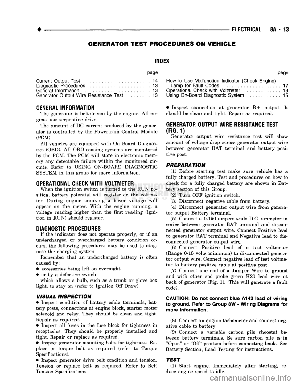
GENERATOR
OUTPUT
WIRE RESISTANCE TEST
(FIG.
1)
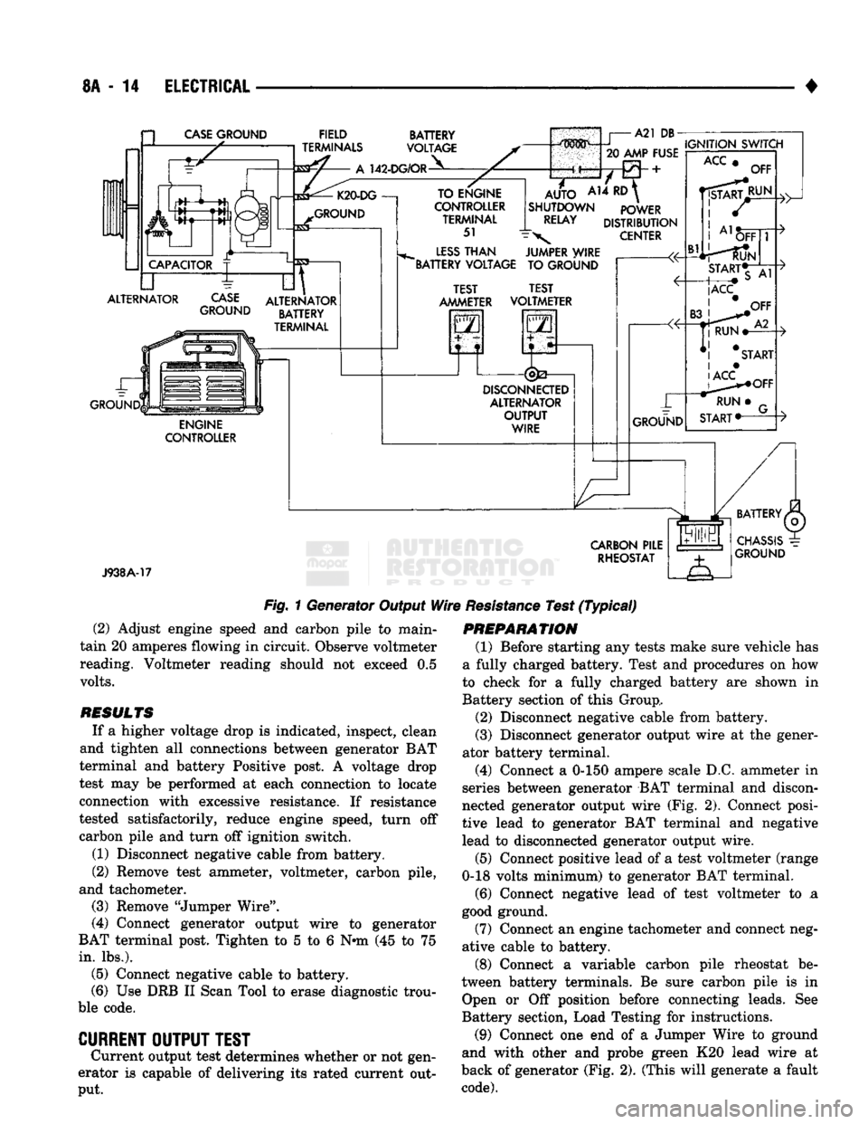
Generator output wire resistance test will show
amount
of
voltage drop across generator output wire
between generator
BAT
terminal
and
battery posi tive post.
PREPARATION
(1) Before starting test make sure vehicle
has a
fully charged battery. Test
and
procedures
on how to
check
for a
fully charged battery
are
shown
in
Bat
tery section
of
this Group.
(2) Turn
OFF
ignition switch.
(3)
Disconnect negative cable from battery.
(4)
Disconnect generator output wire from genera
tor output Battery terminal. (5) Connect
a 0-150
ampere scale
D.C.
ammeter
in
series between generator
BAT
terminal
and
discon
nected generator output wire. Connect Positive lead
to generator
BAT
terminal
and
Negative lead
to
dis connected generator output wire. (6) Connect Positive lead
of a
test voltmeter
(Range
0-18
volts minimum)
to
disconnected genera
tor output wire. Connect negative lead
of
test voltme
ter
to
battery positive cable
at
positive post. (7) Connect
one end of a
Jumper Wire
to
ground
and with other
end
probe green
K20
lead wire
at
back
of
generator
(Fig. 1).
(This will generate
a
fault
code).
CAUTION:
Do not
connect blue
A142
lead
of
wiring
to ground. Refer
to
Group
8W
-
Wiring Diagrams
for
more information.
(8) Connect
an
engine tachometer
and
connect neg
ative cable
to
battery.
(9) Connect
a
variable carbon pile rheostat
be
tween battery terminals.
Be
sure carbon pile
is in
"Open"
or "Off
position before connecting leads.
See
Battery Section, Load Testing
for
instructions.
TEST
(1) Start engine. Immediately after starting,
re
duce engine speed
to
idle.
Page 335 of 1502
8A
- 14
ELECTRICAL
CASE
GROUND
FIELD
TERMINALS
142-DG/OR
BATTERY
VOLTAGE
ALTERNATOR
CASE
GROUND
GROUND ALTERNATOR
BATTERY
TERMINAL
ENGINE
CONTROLLER TO ENGINE
CONTROLLER TERMINAL
51
LESS
THAN
"BATTERY VOLTAGE
m^mm i
A21 DB-
20
AMP FUSE
A14
RD
AUTO
SHUTDOWN
RELAY
IGNITION
SWITCH
POWER
DISTRIBUTION
CENTER
JUMPER WIRE TO GROUND TEST
AMMETER TEST
VOLTMETER
2
i
DISCONNEaED
ALTERNATOR
OUTPUT
WIRE
ACC
OFF
J938A-17
CARBON
PILE
RHEOSTAT
Fig.
1 Generator Output
Wire
Resistance
Test
(Typical)
(2) Adjust engine speed and carbon pile to main
tain 20 amperes flowing in circuit. Observe voltmeter
reading. Voltmeter reading should not exceed 0.5
volts.
RESULTS
If a higher voltage drop is indicated, inspect, clean
and tighten all connections between generator BAT
terminal and battery Positive post. A voltage drop
test may be performed at each connection to locate
connection with excessive resistance. If resistance
tested satisfactorily, reduce engine speed, turn off carbon pile and turn off ignition switch.
(1) Disconnect negative cable from battery.
(2) Remove test ammeter, voltmeter, carbon pile,
and tachometer. (3) Remove "Jumper Wire".
(4) Connect generator output wire to generator
BAT terminal post. Tighten to 5 to 6 Nnn (45 to 75
in.
lbs.). (5) Connect negative cable to battery.
(6) Use DRB II Scan Tool to erase diagnostic trou
ble code.
CURRENT
OUTPUT
TEST
Current output test determines whether or not gen
erator is capable of delivering its rated current out
put.
PREPARATION
(1) Before starting any tests make sure vehicle has
a fully charged battery. Test and procedures on how
to check for a fully charged battery are shown in
Battery section of this Group,
(2) Disconnect negative cable from battery.
(3) Disconnect generator output wire at the gener
ator battery terminal.
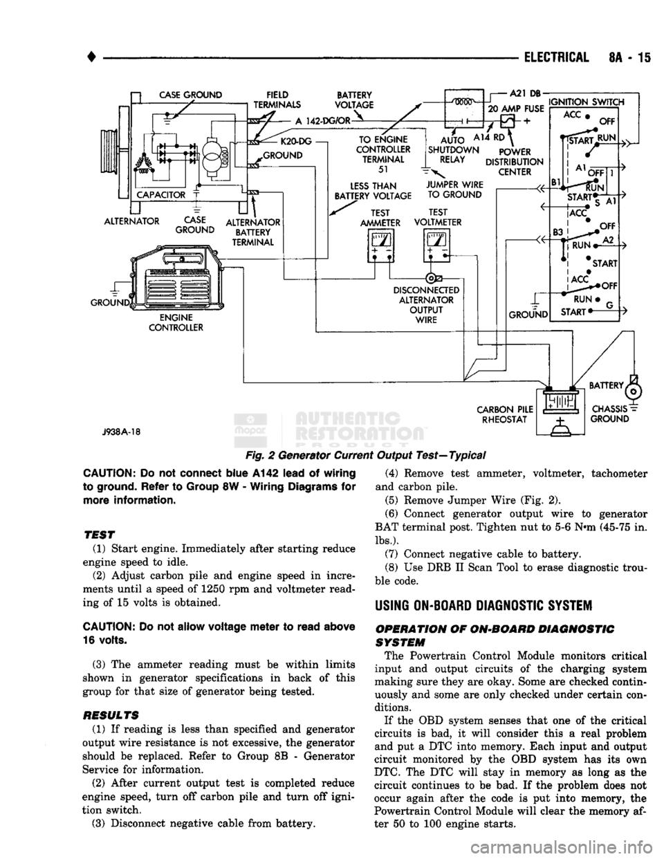
(4) Connect a 0-150 ampere scale D.C. ammeter in
series between generator BAT terminal and discon
nected generator output wire (Fig. 2). Connect posi
tive lead to generator BAT terminal and negative
lead to disconnected generator output wire.
(5) Connect positive lead of a test voltmeter (range
0-18 volts minimum) to generator BAT terminal.
(6) Connect negative lead of test voltmeter to a
good ground.
(7) Connect an engine tachometer and connect neg
ative cable to battery.
(8) Connect a variable carbon pile rheostat be
tween battery terminals. Be sure carbon pile is in Open or Off position before connecting leads. See
Battery section, Load Testing for instructions.
(9) Connect one end of a Jumper Wire to ground
and with other and probe green K20 lead wire at
back of generator (Fig. 2). (This will generate a fault
code).
Page 336 of 1502
•
ELECTRICAL
8A - 15 a
CASE
GROUND
CAPACITOR
ALTERNATOR ~L FIELD
TERMINALS
A
142-DG/OR BATTERY
VOLTAGE K20-DG
—!
GROUND
CASE
GROUND
til
ALTERNATOR BATTERY
TERMINAL ENGINE
CONTROLLER TO ENGINE
CONTROLLER TERMINAL
51
LESS
THAN
BATTERY VOLTAGE A21
DB-
.....
IGNITION SWITCH
20 AMP FUSE
AUTO
AH ^
SHUTDOWN POWER
RELAY
DISTRIBUTION
\
CENTER TEST
AMMETER JUMPER WIRE
TO GROUND
TEST
VOLTMETER
GO
5—n
DISCONNECTED
ALTERNATOR OUTPUT WIRE GROUND
ACC
Bl
OFF
RUN OFF
START*T
|ACC
CARBON
PILE RHEOSTAT
J938A-18
Fig.
2 Generator Current Output Test—Typical
CAUTION:
Do not
connect
blue
A142
lead
of
wiring
to ground.
Refer
to
Group
8W -
Wiring
Diagrams
for
more
information.
TEST
(1) Start engine. Immediately after starting reduce
engine speed to idle. (2) Adjust carbon pile and engine speed in incre
ments until a speed of 1250 rpm and voltmeter read
ing of 15 volts is obtained.
CAUTION:
Do not
allow
voltage
meter
to
read
above
16 volts.
(3) The ammeter reading must be within limits
shown in generator specifications in back of this
group for that size of generator being tested.
RESULTS
(1) If reading is less than specified and generator
output wire resistance is not excessive, the generator
should be replaced. Refer to Group 8B - Generator
Service for information.
(2) After current output test is completed reduce
engine speed, turn off carbon pile and turn off igni
tion switch.
(3) Disconnect negative cable from battery. (4) Remove test ammeter, voltmeter, tachometer
and carbon pile. (5) Remove Jumper Wire (Fig. 2).
(6) Connect generator output wire to generator
BAT terminal post. Tighten nut to 5-6 Nnn (45-75 in.
lbs.).
(7) Connect negative cable to battery.
(8) Use DRB II Scan Tool to erase diagnostic trou
ble code.
USING
ON-BOARD
DIAGNOSTIC
SYSTEM
OPERATION
OF
ON-BOARD
DIAGNOSTIC
SYSTEM
The Powertrain Control Module monitors critical
input and output circuits of the charging system
making sure they are okay. Some are checked contin
uously and some are only checked under certain con
ditions.
If the OBD system senses that one of the critical
circuits is bad, it will consider this a real problem
and put a DTC into memory. Each input and output
circuit monitored by the OBD system has its own
DTC.
The DTC will stay in memory as long as the
circuit continues to be bad. If the problem does not
occur again after the code is put into memory, the
Powertrain Control Module will clear the memory af
ter 50 to 100 engine starts.
Page 338 of 1502
•
ELECTRICAL
8A - 17
DIAGNOSTIC
TROUBLE
CODES
Diagnostic trouble codes are 2 digit numbers
flashed on Malfunction Indicator lamp (Check En
gine) that identify which circuit is bad. In most cases
they do not identify which component in a circuit is
bad. A DTC description can be read using the DRB II scan tool. Refer to Group 14 - Fuel Systems for more
information. Therefore, a DTC is only a result, not
necessarily the reason for the problem. However, in
some cases, as a result of the design of the driveabil- ity test procedure, a DTC can be the reason for the
problem. It is important that the test procedure be followed in order to understand what the DTC of the
on-board diagnostic system are trying to tell.
HOW
TO
USE
MALFUNCTION
INDICATOR
(CHECK
ENGINE)
LAMP
FOR
FAULT
CODES
To activate this function cycle the ignition switch
on-off-on-off-on within 5 seconds and any DTC stored
in the Powertrain Control Module will be displayed.
The Check Engine lamp will display a DTC by flash ing on and off. There is a short pause between
flashes and a longer pause between digits. All codes
displayed are two digit numbers with a four second
pause between codes. An example of a code is as follows:
(1) Lamp on for 2 seconds, then turns off.
(2) Lamp flashes 4 times pauses and then flashes
1.
(3) Lamp pauses for 4 seconds, flashes 4 times,
pauses and then flashes 7 times.
The two codes are 41 and 47. Any number of codes
can be displayed (maximum of 8 faults can be stored) as long as they are in memory. The lamp will flash
until all of them (including 55) are displayed (55 =
End of test).
CHARGING
SYSTEM
FAULT
CODES
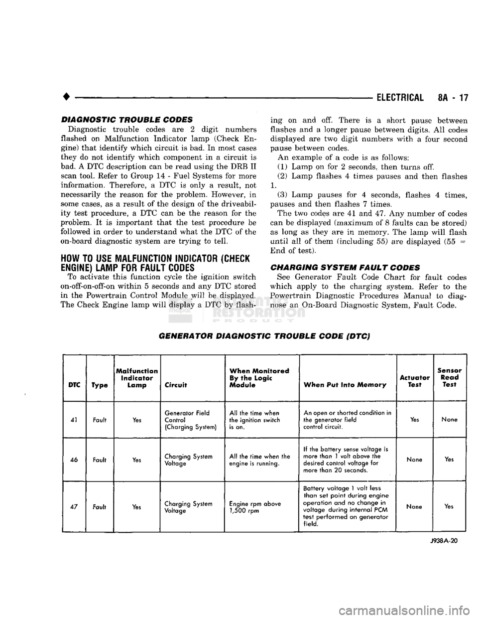
See Generator Fault Code Chart for fault codes
which apply to the charging system. Refer to the
Powertrain Diagnostic Procedures Manual to diag
nose an On-Board Diagnostic System, Fault Code.
GENERATOR
DIAGNOSTIC
TROUBLE
CODE
(DTC)
DTC
Type
Malfunction
Indicator
Lamp
Circuit
When
Monitored
By
the
Logic
Module
When
Put Into
Memory
Actuator
Test
Sensor
Read
Test
41 Fault
Yes
Generator Field
Control
(Charging
System)
All the
time
when
the ignition switch
is
on.
An
open or shorted condition in
the generator
field
control circuit.
Yes
None
46 Fault
Yes
Charging
System
Voltage
All the
time
when the
engine
is
running.
If the
battery
sense
voltage is
more than 1 volt
above
the
desired
control voltage for
more than 20
seconds.
None
Yes
47 Fault
Yes
Charging
System
Voltage
Engine
rpm
above
1,500 rpm Battery voltage
1
volt
less
than set point during engine
operation and no
change
in
voltage
during
internal
PCM
test performed on generator field.
None
Yes
J938A-20
Page 348 of 1502
•
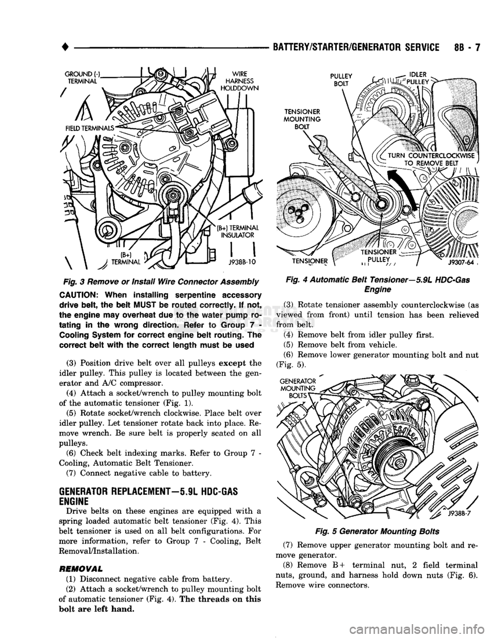
Fig.
3
Remove
or install
Wire
Connector
Assembly
CAUTION:
When
installing
serpentine
accessory
drive
belt,
the
belt
MUST
be
routed
correctly.
If not,
the engine may overheat due to the
water
pump ro
tating
in the wrong
direction.
Refer to Group 7 -
Cooling
System
for
correct
engine
belt
routing.
The
correct
belt
with
the
correct
length
must be
used
(3) Position drive belt over all pulleys except the
idler pulley. This pulley is located between the gen
erator and A/C compressor.
(4) Attach a socket/wrench to pulley mounting bolt
of the automatic tensioner (Fig. 1).
(5)
Rotate socket/wrench clockwise. Place belt over
idler pulley. Let tensioner rotate back into place. Re
move wrench. Be sure belt is properly seated on all
pulleys.
(6) Check belt indexing marks. Refer to Group 7 -
Cooling, Automatic Belt Tensioner.
(7) Connect negative cable to battery.
GENERATOR
REPLACEMENT—5.9L
HDC-GAS
ENGINE
Drive belts on these engines are equipped with a
spring loaded automatic belt tensioner (Fig. 4). This
belt tensioner is used on all belt configurations. For more information, refer to Group 7 - Cooling, Belt
Removal/Installation.
REMOVAL
(1) Disconnect negative cable from battery.
(2) Attach a socket/wrench to pulley mounting bolt
of automatic tensioner (Fig. 4). The threads on this
bolt are left hand.
BATTERY/STARTER/GENERATOR
SERVICE
8B - 7
Fig.
4 Automatic Belt Tensioner—5.9L
HDC-Gas
Engine
(3) Rotate tensioner assembly counterclockwise (as
viewed from front) until tension has been relieved
from belt.
(4) Remove belt from idler pulley first.
(5) Remove belt from vehicle.
(6) Remove lower generator mounting bolt and nut
(Fig. 5).
Fig.
5 Generator
Mounting
Bolts
(7) Remove upper generator mounting bolt and re
move generator.
(8) Remove B+ terminal nut, 2 field terminal
nuts,
ground, and harness hold down nuts (Fig. 6).
Remove wire connectors.