1993 DODGE TRUCK check engine
[x] Cancel search: check enginePage 444 of 1502
•
LAMPS
LAMPS
8L - 1
CONTENTS
page page
BULB
APPLICATION 11 EXTERIOR
LAMPS
SERVICE
PROCEDURES
... 3
EXTERIOR
LAMPS
1 INTERIOR
LAMPS
10
EXTERIOR LAMPS
GENERAL
INFORMATION Each vehicle is equipped with various lamp assem
blies.
A good ground is necessary for proper lighting operation. When changing lamp bulbs check the socket for
corrosion. Clean corrosion with a wire brush. Coat
the inside of the socket lightly with Mopar® Multi- Purpose Grease or equivalent.
DIAGNOSTIC
PROCEDURES
Always begin any diagnosis by testing all of the
fuses and circuit breakers in the system. Refer to Group 8W, Wiring Diagrams. Conventional and halogen headlamps are inter
changeable. It is recommended that they not be in
termixed on a given vehicle.
MULTI-FUNCTION
SWITCH TESTING
PROCEDURES
The multi-function switch contains electrical cir
cuitry for:
• Headlamp Dimmer Switch
• Passing Lights
• Turn Signals
• Hazard Warning • Windshield Wiper
• Pulse Wiper
• Windshield Washer
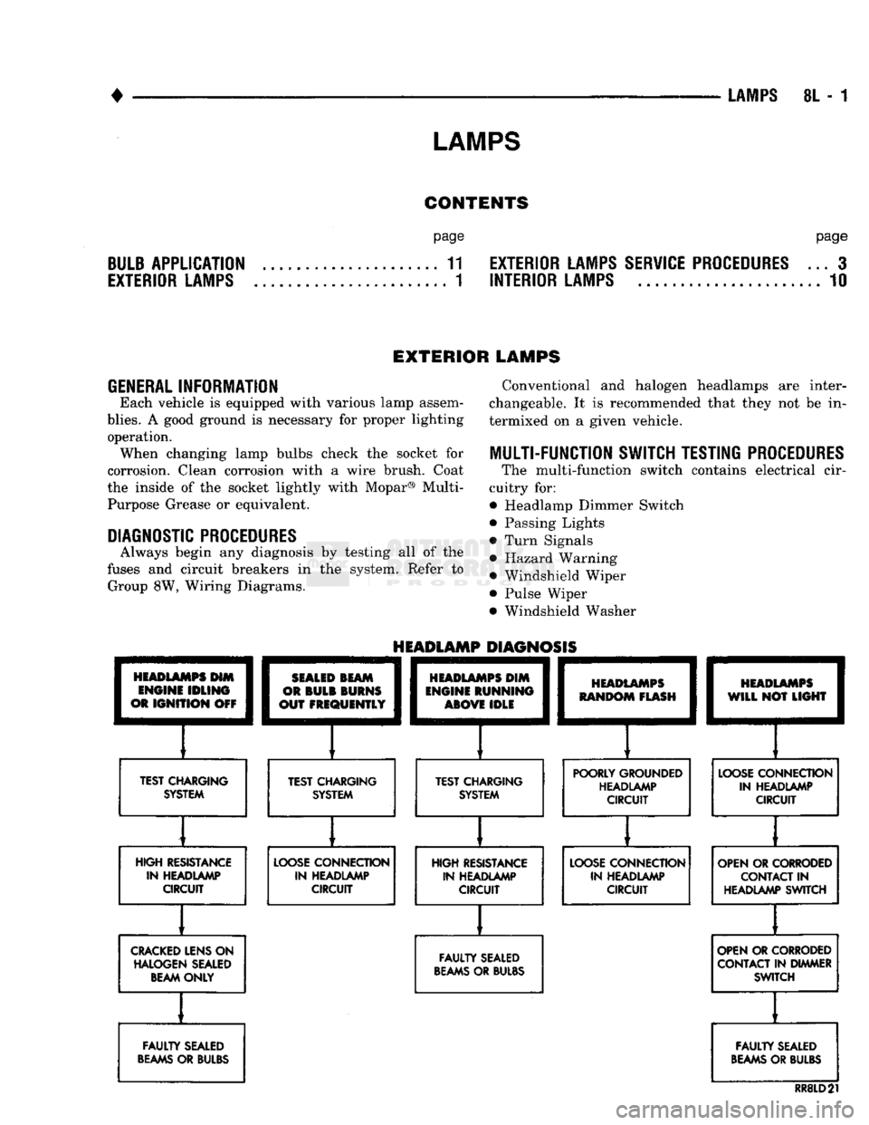
HEADLAMPS
HIM
ENGINE
IDLING
OR
IGNITION
OFF
TEST CHARGING
SYSTEM
HEADLAMP
DIAGNOSIS
SEALED
BEAM
OR
BULB
BURNS
OUT
FREQUENTLY
][
TEST CHARGING SYSTEM
HEADLAMPS
DIM
ENGINE
RUNNING
ABOVE
IDLE
][
TEST CHARGING SYSTEM
HEADLAMPS
RANDOM
FLASH
[
HEADLAMPS
WILL
NOT
LIGHT
POORLY GROUNDED HEADLAMP CIRCUIT
LOOSE
CONNECTION
IN HEADLAMP CIRCUIT
HIGH RESISTANCE IN HEADLAMP CIRCUIT
LOOSE
CONNECTION
IN HEADLAMP CIRCUIT HIGH RESISTANCE
IN HEADLAMP CIRCUIT
LOOSE
CONNECTION
IN HEADLAMP CIRCUIT OPEN OR CORRODED
CONTACT
IN
HEADLAMP SWITCH
CRACKED
LENS ON HALOGEN SEALED BEAM ONLY
FAULTY
SEALED
BEAMS
OR BULBS OPEN OR CORRODED
CONTACT IN DIMMER SWITCH
FAULTY
SEALED
BEAMS
OR BULBS
FAULTY
SEALED
BEAMS
OR BULBS
RR8LD21
Page 454 of 1502
•
LAMPS
8L - 11
BULB
APPLICATION
GENERAL
INFORMATION
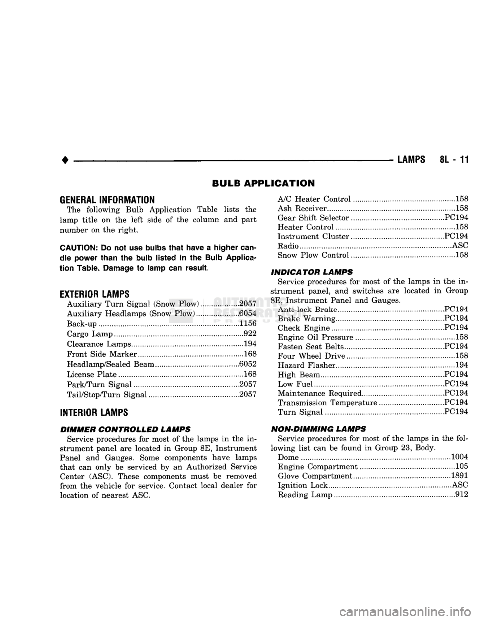
The following Bulb Application Table lists
the
lamp title
on the
left side
of the
column
and
part
number
on the
right.
CAUTION:
Do not use
bulbs
that
have
a
higher
can
dle power than
the
bulb
listed
in the
Bulb
Applica
tion Table.
Damage
to
lamp
can
result.
EXTERIOR LAMPS
Auxiliary Turn Signal (Snow Plow) 2057
Auxiliary Headlamps (Snow Plow) .6054
Back-up....................... .......1156 Cargo Lamp..
922
Clearance Lamps
194
Front Side Marker
168
Headlamp/Sealed Beam .6052
License Plate
168
Park/Turn Signal 2057
TaiyStop/Turn Signal ...2057
INTERIOR LAMPS
DIMMER CONTROLLED LAMPS Service procedures
for
most
of the
lamps
in the in
strument panel
are
located
in
Group
8E,
Instrument
Panel
and
Gauges. Some components have lamps
that
can
only
be
serviced
by an
Authorized Service Center (ASC). These components must
be
removed
from
the
vehicle
for
service. Contact local dealer
for
location
of
nearest
ASC.
A/C Heater Control
158
Ash Receiver
..158
Gear Shift Selector...........................................PC194
Heater Control
158
Instrument Cluster.. PC 194
Radio
ASC
Snow Plow Control
.158
INDICATOR LAMPS Service procedures
for
most
of the
lamps
in the in
strument panel,
and
switches
are
located
in
Group
8E,
Instrument Panel
and
Gauges. Anti-lock Brake PC194
Brake Warning PC194 Check Engine PC194
Engine
Oil
Pressure
158
Fasten Seat Belts.. PC 194 Four Wheel Drive ....158
Hazard Flasher
194
High Beam PC194
Low Fuel....... JPC194
Maintenance Required PC 194
Transmission Temperature ..PC 194 Turn Signal PC194
NON-DIMMING LAMPS Service procedures
for
most
of the
lamps
in the
fol
lowing list
can be
found
in
Group
23,
Body.
Dome
1004
Engine Compartment ...105 Glove Compartment....
1891
Ignition Lock
ASC
Reading Lamp
912
Page 456 of 1502
•
REAR
WINDOW DEFOGGER
8N - 1
REAR
WINDOW
DEFOGGER
CONTENTS
page
REPAIR
PROCEDURES (GRID LINES,
TERMINALS,
AND
PIGTAILS)
3
GENERAL
INFORMATION
The electrically heated rear window defogger
is
available
on
Ramcharger with sunscreen glass only. The system consists
of a
rear window with
two
ver
tical
bus
bars
and a
series
of
electrically connected
grid lines baked
on the
inside surface. Circuit protection
for the
heated grid circuit
is
pro
vided
by a 18
gauge fusible link wire located
in the
engine compartment.
The
relay circuit
is
protected
by
a 20 amp
fuse, located
in the
fuse block. When
the
rear window defogger switch
is
placed
in
the
ON
position, current
is
directed
to
rear window
grid lines.
The
heated grid lines
in
turn heat
the
rear window
to
clear
the
surface
of fog or
snow.
CAUTION;
Grid lines
can be
damaged
or
scraped
off
with
sharp instruments. Care should
be
taken
in
page
SERVICE
PROCEDURES
4
TEST
PROCEDURES
1
cleaning
the
glass
or
removing foreign materials,
decals
or
stickers. Normal
glass
cleaning solvents
or
hot
water
used
with
rags
or
toweling
is
recom mended.
SYSTEM
DESCRIPTION CONTROL
SWITCH/TIMER
RELAY MODULE
The control switch
and
timer relay
are
integrated
into
a
single panel mounted assembly. Actuating
the
switch energizes
the
electronic timing circuit. This
allows current
to
flow through
the
grid system
for
approximately
10
minutes,
or
until either
the
control
switch
or
ignition
is
turned
off. An
indicating lamp
illuminates
a
lens inlaid
in the
control switch.
TEST PROCEDURES
SYSTEM
TEST
Electrically heated rear window defogger operation
can
be
checked in-vehicle
in the
following manner: (1) Turn
the
ignition
ON.
(2) Turn rear window defogger control switch
ON.
(3) Monitor vehicle voltmeter. With
the
control
switch
ON, a
distinct needle deflection should
be
noted. (4)
The
rear window defogger operation
can be
checked
by
feeling
the
glass.
A
distinct difference
in
temperature between
the
grid lines
and
adjacent clear glass
can be
detected
in 3 to 4
minutes
of
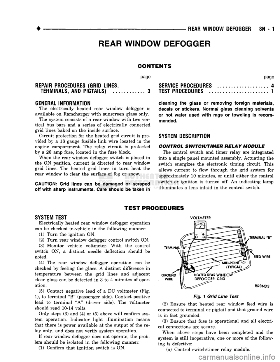
operation. (5) Contact negative lead
of a DC
voltmeter
(Fig.
1),
to
terminal
"B"
(passenger side). Contact positive
lead
to
terminal
"A"
(driver side).
The
voltmeter
should read
10-14
volts. Only steps
(3) and (4) or (5)
above will confirm sys
tem operation. Indicator light illumination means
that there
is
power available
at the
output
of the re
lay only,
and
does
not
verify system operation.
If rear window defogger does
not
operate,
the
prob
lem should
be
isolated
in the
following manner:
(1) Confirm that ignition switch
is ON.
VOLTMETER
Fig.
1
Grid
Line
Test (2) Ensure that heated rear window feed wire
is
connected
to
terminal
or
pigtail
and
that ground wire
is
in
fact grounded.
(3) Ensure that fuse
is
operational
and all
electri
cal connections
are
secure.
When above steps have been completed
and the
system
is
still inoperative,
one or
more
of the
follow
ing
is
defective:
(a) Control switch/timer relay module.
Page 478 of 1502
•
WIRING
DIAGRAMS
8W - 3 fer to a components name in the index if you are
unclear as to what a system may be called.
Diagram pages are arranged starting with the bat
tery and fuses. Then working into charging, starting, and ignition systems. After this they start at the
front of the vehicle and work to rear of the vehicle.
The diagrams end with connector identification
pages.
COMPONENT
IDENTIFICATION
To find a components actual location on the vehicle
refer to the wiring and components section index. This section shows the wire harness routing and the compo
nents location in the vehicle. When using this section
refer to the wiring diagrams for the general location of
the component. Then use the component identification index to locate the proper figure number.
SPLICE
LOCATIONS
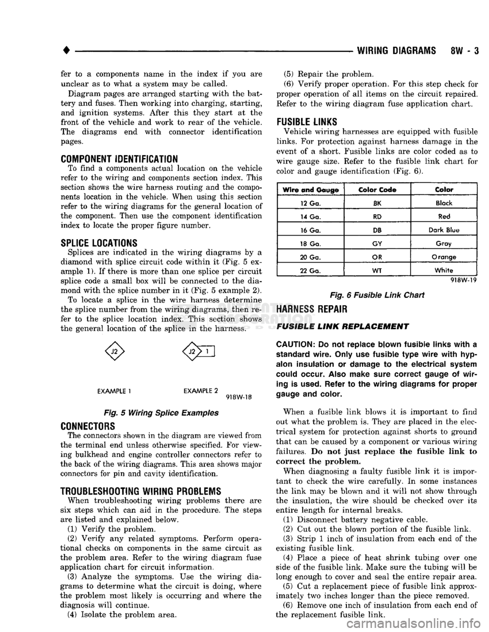
Splices are indicated in the wiring diagrams by a
diamond with splice circuit code within it (Fig. 5 ex ample 1). If there is more than one splice per circuit
splice code a small box will be connected to the dia
mond with the splice number in it (Fig. 5 example 2). To locate a splice in the wire harness determine
the splice number from the wiring diagrams, then re
fer to the splice location index. This section shows
the general location of the splice in the harness.
EXAMPLE
1
EXAMPLE
2 918W-18
Fig.
5 Wiring
Splice
Examples
CONNECTORS
The connectors shown in the diagram are viewed from
the terminal end unless otherwise specified. For view ing bulkhead and engine controller connectors refer to
the back of the wiring diagrams. This area shows major connectors for pin and cavity identification.
TROUBLESHOOTING
WIRING
PROBLEMS
When troubleshooting wiring problems there are
six steps which can aid in the procedure. The steps
are listed and explained below. (1) Verify the problem.
(2) Verify any related symptoms. Perform opera
tional checks on components in the same circuit as the problem area. Refer to the wiring diagram fuse
application chart for circuit information. (3) Analyze the symptoms. Use the wiring dia
grams to determine what the circuit is doing, where
the problem most likely is occurring and where the diagnosis will continue. (4) Isolate the problem area. (5) Repair the problem.
(6) Verify proper operation. For this step check for
proper operation of all items on the circuit repaired. Refer to the wiring diagram fuse application chart.
FUSIBLE
LINKS
Vehicle wiring harnesses are equipped with fusible
links.
For protection against harness damage in the
event of a short. Fusible links are color coded as to
wire gauge size. Refer to the fusible link chart for color and gauge identification (Fig. 6).
Wire and
Gauge
Color
Code
Color
12 Ga.
BK
Black
14 Ga.
RD
Red
16 Ga.
DB
Dark
Blue
18 Ga.
GY
Gray
20 Ga.
OR
Orange
22 Ga.
WT
White
918W-19
Fig.
6 Fusible
Link
Chart
HARNESS
REPAIR
FUSIBLE
LINK
REPLACEMENT
CAUTION:
Do not replace blown fusible
links
with
a
standard
wire.
Only
use fusible type
wire
with
hyp-
alon
insulation or
damage
to the electrical
system
could
occur.
Also
make
sure
correct
gauge
of
wir
ing
is
used.
Refer to the wiring
diagrams
for proper
gauge
and
color.
When a fusible link blows it is important to find
out what the problem is. They are placed in the elec
trical system for protection against shorts to ground
that can be caused by a component or various wiring
failures. Do not just replace the fusible link to correct the problem.
When diagnosing a faulty fusible link it is impor
tant to check the wire carefully. In some instances
the link may be blown and it will not show through the insulation, the wire should be checked over its
entire length for internal breaks.
(1) Disconnect battery negative cable.
(2) Cut out the blown portion of the fusible link.
(3) Strip 1 inch of insulation from each end of the
existing fusible link.
(4) Place a piece of heat shrink tubing over one
side of the fusible link. Make sure the tubing will be
long enough to cover and seal the entire repair area.
(5) Cut a replacement piece of fusible link approx
imately two inches longer than the piece removed. (6) Remove one inch of insulation from each end of
the replacement fusible link.
Page 482 of 1502
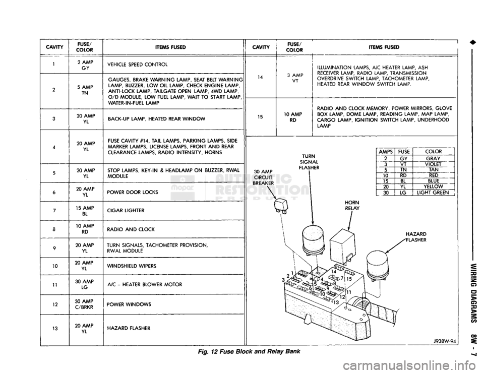
CAVITY
FUSE/
COLOR ITEMS FUSED
CAVITY
FUSE/
COLOR ITEMS FUSED
10
11
12
13 2 AMP
GY VEHICLE SPEED CONTROL
5 AMP TN
GAUGES,
BRAKE WARNING LAMP, SEAT BELT WARNING
LAMP, BUZZER, LOW OIL LAMP, CHECK ENGINE LAMP,
ANTI-LOCK LAMP, TAILGATE OPEN LAMP, 4WD LAMP, O/D MODULE, LOW FUEL LAMP,
WAIT
TO START LAMP
WATER-IN-FUEL LAMP 14
3 AMP
VT
20 AMP YL BACK-UP LAMP, HEATED REAR WINDOW
15 10 AMP
RD
ILLUMINATION
LAMPS, A/C HEATER LAMP, ASH
RECEIVER LAMP, RADIO LAMP, TRANSMISSION
OVERDRIVE SWITCH LAMP, TACHOMETER LAMP, HEATED REAR WINDOW SWITCH LAMP.
RADIO AND CLOCK MEMORY, POWER MIRRORS, GLOVE BOX LAMP, DOME LAMP, READING LAMP, MAP LAMP,
CARGO LAMP,
IGNITION
SWITCH LAMP, UNDERHOOD LAMP
20 AMP YL FUSE CAVITY #14,
TAIL
LAMPS, PARKING LAMPS, SIDE
AAARKER
LAMPS, LICENSE LAMPS, FRONT AND REAR CLEARANCE LAMPS, RADIO INTENSITY, HORNS
20 AMP YL STOP LAMPS, KEY-IN & HEADLAMP ON BUZZER, RWAL
MODULE 30 AMP
CIRCUIT
BREAKER
TURN
SIGNAL
FLASHER 20 AMP
YL POWER DOOR LOCKS
15 AMP
BL
CIGAR LIGHTER
10 AMP RD RADIO AND CLOCK
20 AMP YL
TURN
SIGNALS, TACHOMETER PROVISION,
RWAL MODULE
20 AMP YL WINDSHIELD WIPERS
30 AMP LG A/C - HEATER BLOWER MOTOR
30 AMP
C/BRKR
POWER WINDOWS
20 AMP YL HAZARD FLASHER
AMPS
FUSE
COLOR
2 GY GRAY
3 VT
VIOLET
5 TN
TAN
10 RD
RED
15
BL
BLUE
20 YL YELLOW
30 LG
LIGHT
GREEN HAZARD
FLASHER
J938W-94
Fig. 12 Fuse Block and
Relay
Bank
Page 607 of 1502

9
- 2
ENGINES
rial surrounds each mounting hole. Excess material
can easily be wiped off. Components should be
torqued in place within 15 minutes. The use of a lo cating dowel is recommended during assembly to pre
vent smearing the material off location.
ENGINE PERFORMANCE
To provide best vehicle performance and lowest ve
hicle emissions, it is most important that the tune-up
be done accurately. Use the specifications listed on
the Vehicle Emission Control Information label found on the engine compartment hood.
(1) Test cranking amperage draw (refer to Group
8B,
Battery/Starter/Generator Service for the proper
procedures).
(2) Tighten the intake manifold bolts (refer to
Group 11, Exhaust System and Intake Manifold for
the proper specifications). (3) Perform cylinder compression test:
(a) Check engine oil level and add oil, if neces
sary.
(b) Drive the vehicle until engine reaches normal
operating temperature. (c) Select a route free from traffic and other
forms of congestion, observe all traffic laws and
briskly accelerate through the gears several times. The higher engine speed may help clean out valve seat deposits which can prevent accurate compres
sion readings.
CAUTION:
DO NOT
overspeed
the
engine.
(d) Remove all spark plugs from engine. As
spark plugs are being removed, check electrodes for
abnormal firing indicators - fouled, hot, oily, etc.
Record cylinder number of spark plug for future
reference.
(e) Disconnect coil wire from distributor and se
cure to good ground to prevent a spark from start
ing a fire.
(f) Be sure throttle blades are fully open during
the compression check. (g) Insert compression gage adaptor into the
No.l spark plug hole. Crank engine until maxi
mum pressure is reached on gauge. Record this
pressure as No.l cylinder pressure.
(h) Repeat Step 3g for all remaining cylinders.
(i) Compression should not be less than 689 kPa
(100 psi) and not vary more than 172 kPa (25 psi)
from cylinder to cylinder.
(j) If cylinder(s) have abnormally low compres
sion pressures, repeat steps 3a through 3h. (k) If the same cylinder(s) repeat an abnormally
low reading, it could indicate the existence of a
problem in the cylinder.
The recommended compression pressures are
to be used only as a guide to diagnosing engine
problems. An engine should NOT be disassem bled to determine the cause of low compression
unless some malfunction is present. (4) Clean or replace spark plugs as necessary. Ad
just gap (refer to Group 8D, Ignition System for gap adjustment and torque).
(5) Test resistance of spark plug cables (refer to
Group 8D, Ignition System.
(6) Inspect the primary wire. Test coil output volt
age,
primary and secondary resistance. Replace parts as necessary (refer to Group 8D, Ignition System and
make necessary adjustment).
(7) Set ignition timing to specifications (refer to
Specification Label on engine compartment hood).
(8) Perform a combustion analysis.
(9) Test fuel pump for pressure and vacuum (refer
to Group 14, Fuel System for the proper specifica
tions).
(10) Inspect air filter element (refer to Group 0,
Lubrication and Maintenance for the proper proce
dure).
(11) Inspect crankcase ventilation system (refer to
Group 0, Lubrication and Maintenance for the proper
procedure).
(12) For emission controls refer to Group 25, Emis
sion Controls System for service procedures.
(13) Inspect and adjust accessory belt drives (refer
to Group 7, Cooling System for the proper adjust
ments).
(14) Road test vehicle as a final test.
H0NIN6
CYLINDER
BORES
Before honing, stuff plenty of clean shop towels un
der the bores and over the crankshaft to keep abra sive materials from entering the crankshaft area.
(1) Used carefully, the Cylinder Bore Sizing Hone
C-823 equipped with 220 grit stones, is the best tool
for this job. In addition to deglazing, it will reduce
taper and out-of-round as well as removing light scuffing, scoring or scratches. Usually a few strokes
will clean up a bore and maintain the required lim
its.
CAUTION:
DO NOT use rigid type
hones
to remove
cylinder
wall
glaze.
(2) Deglazing of the cylinder walls may be done if
the cylinder bore is straight and round. Use a cylin
der surfacing hone, Honing Tool C-3501, equipped
with 280 grit stones (C-3501-3810). 20-60 strokes, de
pending on the bore condition, will be sufficient to
provide a satisfactory surface. Using honing oil C-3501-3880 or a light honing oil available from ma
jor oil distributors.
CAUTION:
DO NOT use engine or
transmission
oil, mineral
spirits
or
kerosene.
Page 608 of 1502
•
ENGINES
9 - 3
(3) Honing
should be
done
by moving the
hone
up
and down
fast
enough
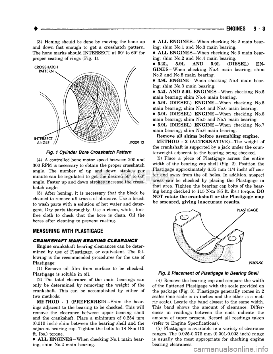
to get a Crosshatch pattern.
The hone
marks should
INTERSECT
at 50° to 60° for
proper seating
of
rings (Fig.
1).
Fig.
1
Cylinder
Bore
Crosshatch
Pattern
(4)
A
controlled hone motor speed between
200 and
300
RPM is
necessary
to
obtain
the
proper Crosshatch angle.
The
number
of up and
down strokes
per
minute
can be
regulated
to get the
desired
50° to 60°
angle. Faster
up and
down strokes increase
the
cross-
hatch angle.
(5) After honing,
it is
necessary that
the
block
be
cleaned
to
remove
all
traces
of
abrasive.
Use a
brush
to wash parts with
a
solution
of hot
water
and
deter gent.
Dry
parts thoroughly.
Use a
clean, white, lint-
free cloth
to
check that
the
bore
is
clean.
Oil the
bores after cleaning
to
prevent rusting.
MEASURING
WITH
PLASTIGAGE
CRANKSHAFT
MAIN BEARING CLEARANCE Engine crankshaft bearing clearances
can be
deter
mined
by use of
Plastigage,
or
equivalent.
The
fol lowing
is the
recommended procedures
for the use of
Plastigage:
(1) Remove
oil
film from surface
to be
checked.
Plastigage
is
soluble
in oil.
(2)
The
total clearance
of the
main bearings
can
only
be
determined
by
removing
the
weight
of the
crankshaft. This
can be
accomplished
by
either
of
two methods:
METHOD - 1
(PREFERRED)—Shim
the
bear
ings adjacent
to the
bearing
to be
checked. This will
remove
the
clearance between upper bearing shell and
the
crankshaft. Place
a
minimum
of
0.254
mm
(0.010 inch) shim between
the
bearing shell
and the
adjacent bearing cap. Tighten
the
bolts
to 18 N*m (13
ft.
lbs.)
torque. •
ALL
ENGINES—When checking
No.l
main bear
ing; shim
No.2
main bearing. •
ALL
ENGINES-When checking
No.2
main bear
ing; shim
No.l and No.3
main bearing.
•
ALL
ENGINES-When checking No.3 main bear
ing; shim
No.2 and No.4
main bearing.
•
5.2L, 5.9L AND 5.9L
(DIESEL)
EN
GINES—When checking
No.4
main bearing; shim
No.3
and No.5
main bearing.
•
3.9L
ENGINE—When checking
No.4
main bear
ing; shim
No.3
main bearing.
•
5.2L AND 5.9L
ENGINES—When checking
No.5
main bearing; shim
No.4
main bearing.
•
5.9L
(DIESEL) ENGINE-When checking
No.5
main bearing; shim
No.4 and No.6
main bearing.
•
5.9L
(DIESEL) ENGINE-When checking
No.6
main bearing; shim
No.5 and No.7
main bearing.
•
5.9L
(DIESEL) ENGINE-When checking
No.7
main bearing; shim
No.6
main bearing.
Remove
all
shims before assembling engine.
METHOD
- 2
(ALTERNATIVE)—The weight
of
the crankshaft
is
supported
by a
jack under
the
coun
terweight adjacent
to the
bearing being checked.
(3) Place
a
piece
of
Plastigage across
the
entire
width
of the
bearing
cap
shell
(Fig. 2).
Position
the
Plastigage approximately
6.35 mm (1/4
inch)
off
cen
ter
and
away from
the oil
holes.
In
addition, suspect areas
can be
checked
by
placing
the
Plastigage
in
that area. Tighten
the
bearing
cap
bolts
of the
bear
ing being checked
to 115 N»m (85 ft. lbs.)
torque.
DO
NOT rotate
the
crankshaft
or the
Plastigage
may
be smeared, giving inaccurate results.
Fig.
2
Placement
of
Plastigage
in
Bearing
Shell
(4) Remove
the
bearing
cap and
compare
the
width
of
the
flattened Plastigage with
the
scale provided
on
the package
(Fig. 3).
Plastigage generally comes
in 2
scales
(one
scale
is in
inches
and the
other
is a
met
ric scale). Locate
the
band closest
to the
same width.
This band shows
the
amount
of
clearance. Differ ences
in
readings between
the
ends indicate
the
amount
of
taper present. Record
all
readings taken (refer
to
Engine Specifications).
(5) Plastigage
is
available
in a
variety
of
clearance
ranges.
The
0.025-0.076
mm
(0.001-0.003 inch) range is usually
the
most appropriate
for
checking engine
bearing clearances.
Page 609 of 1502
9
- 4 ENGINES
•
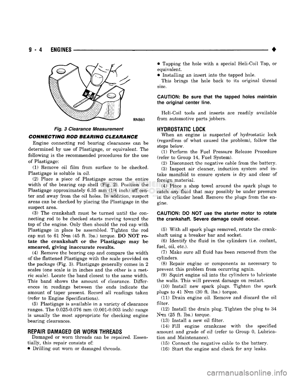
RN861
Fig. 3 Clearance Measurement
CONNECTING ROD BEARING CLEARANCE Engine connecting rod bearing clearances can be
determined by use of Plastigage, or equivalent. The
following is the recommended procedures for the use of Plastigage:
(1) Remove oil film from surface to be checked.
Plastigage is soluble in oil.
(2) Place a piece of Plastigage across the entire
width of the bearing cap shell (Fig. 2). Position the
Plastigage approximately 6.35 mm (1/4 inch) off cen
ter and away from the oil holes. In addition, suspect areas can be checked by placing the Plastigage in the
suspect area. (3) The crankshaft must be turned until the con
necting rod to be checked starts moving toward the
top of the engine. Only then should the rod cap with
Plastigage in place be assembled. Tighten the rod
cap nut to 61 Nnn (45 ft. lbs.) torque. DO NOT ro
tate the crankshaft or the Plastigage may be smeared, giving inaccurate results. (4) Remove the bearing cap and compare the width
of the flattened Plastigage with the scale provided on
the package (Fig. 3). Plastigage generally comes in 2 scales (one scale is in inches and the other is a met
ric scale). Locate the band closest to the same width.
This band shows the amount of clearance. Differ ences in readings between the ends indicate the
amount of taper present. Record all readings taken (refer to Engine Specifications). (5) Plastigage is available in a variety of clearance
ranges. The 0.025-0.076 mm (0.001-0.003 inch) range
is usually the most appropriate for checking engine
bearing clearances.
REPAIR DAMAGED OR WORN THREADS Damaged or worn threads can be repaired. Essen
tially, this repair consists of:
• Drilling out worn or damaged threads. • Tapping the hole with a special Heli-Coil Tap, or
equivalent.
• Installing an insert into the tapped hole.
This brings the hole back to its original thread
size.
CAUTION:
Be
sure
that
the tapped holes maintain
the original
center
line.
Heli-Coil tools and inserts are readily available
from automotive parts jobbers.
HYDROSTATIC
LOCK
When an engine is suspected of hydrostatic lock
(regardless of what caused the problem), follow the
steps below. (1) Perform the Fuel Pressure Release Procedure
(refer to Group 14, Fuel System). (2) Disconnect the negative cable from the battery.
(3) Inspect air cleaner, induction system and in
take manifold to ensure system is dry and clear of
foreign material. (4) Place a shop towel around the spark plugs to
catch any fluid that may possibly be under pressure
in the cylinder head. Remove the plugs from the en
gine.
CAUTION:
DO NOT use the starter motor to
rotate
the
crankshaft.
Severe
damage
could
occur.
(5) With all spark plugs removed, rotate the crank
shaft using a breaker bar and socket.
(6) Identify the fluid in the cylinders (i.e. coolant,
fuel, oil, etc.).
(7) Make sure all fluid has been removed from the
cylinders. (8) Repair engine or components as necessary to
prevent this problem from occurring again.
(9) Squirt engine oil into the cylinders to lubricate
the walls. This will prevent damage on restart.
(10) Install new spark plugs. Tighten the spark
plugs to 41 N#m (30 ft. lbs.) torque. (11) Drain engine oil. Remove and discard the oil
filter.
(12) Install the drain plug. Tighten the plug to 34
N-m (25 ft. lbs.) torque.
(13) Install a new oil filter.
(14) Fill engine crankcase with the specified
amount and grade of oil (refer to Group 0, Lubrica
tion and Maintenance). (15) Connect the negative cable to the battery.
(16) Start the engine and check for any leaks.