1993 DODGE TRUCK check engine
[x] Cancel search: check enginePage 397 of 1502
8E - 16 INSTRUMENT PANEL AND GAUGES
• SWITCH AND
PANEL
COMPONENT
SERVICE
INDEX
page
Ash
Tray
20
Cigar
Lighter
........................ 20
Four
Wheel Drive
Indicator
19
Fuse
Block
and
Flashers
................... 19
Glove
Box 21
Heater A/C Control
17
page
Heater Control
16
Hood
Release
19
Illumination
Bulb Replacement
22
Message
Center Module
................... 18
Steering Column Lowering
and
Raising
16
Switches
17
DISCONNECT NEGATIVE CABLE FEOM
BATTERY IN ENGINE COMPAETMENT BE FORE SERVICING INSTRUMENT PANEL.
STEERING COLUMN LOWERING AND RAISING When servicing the instrument panel and the Low
ering and Raising of the steering column is required,
the following is the procedure for doing so: This procedure is not for removing and replac
ing the steering column. Refer to Group - 19 Steering of this manual for the removal and re
placement procedures.
LOWERING STEERING COLUMN
(1) Disconnect negative cable from battery.
(2)
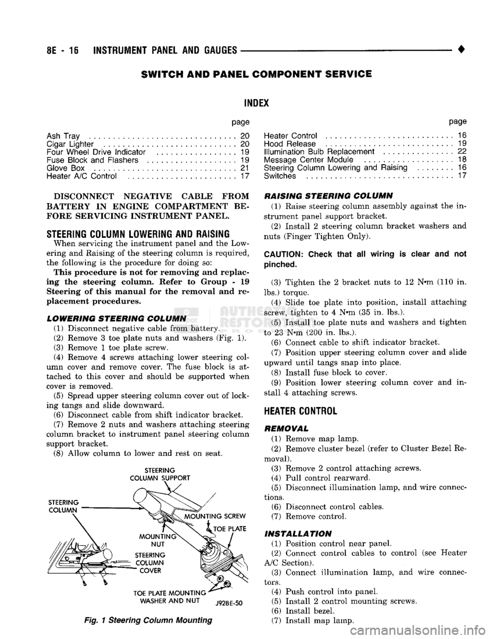
Remove 3 toe plate nuts and washers (Fig. 1).
(3) Remove 1 toe plate screw.
(4) Remove 4 screws attaching lower steering col
umn cover and remove cover. The fuse block is at
tached to this cover and should be supported when cover is removed.
(5) Spread upper steering column cover out of lock
ing tangs and slide downward.
(6)
Disconnect cable from shift indicator bracket.
(7)
Remove 2 nuts and washers attaching steering
column bracket to instrument panel steering column support bracket.
(8)
Allow column to lower and rest on seat.
STEERING
COLUMN SUPPORT
WASHER
AND NUT
Fig.
1 Steering
Column
Mounting
RAISING STEERING COLUMN
(1) Raise steering column assembly against the in
strument panel support bracket. (2) Install 2 steering column bracket washers and
nuts (Finger Tighten Only).
CAUTION:
Check that
all
wiring
is
clear
and not
pinched.
(3) Tighten the 2 bracket nuts to 12 Nnn-(110 in.
lbs.) torque. (4) Slide toe plate into position, install attaching
screw, tighten to 4 N®m (35 in. lbs.).
(5) Install toe plate nuts and washers and tighten
to 23 N*m (200 in. lbs.).
(6)
Connect cable to shift indicator bracket.
(7)
Position upper steering column cover and slide
upward until tangs snap into place.
(8) Install fuse block to cover.
(9)
Position lower steering column cover and in
stall 4 attaching screws.
HEATER CONTROL
REMOVAL
(1) Remove map lamp.
(2) Remove cluster bezel (refer to Cluster Bezel Re
moval). (3) Remove 2 control attaching screws. (4) Pull control rearward.
(5) Disconnect illumination lamp, and wire connec
tions.
(6)
Disconnect control cables.
(7)
Remove control.
INSTALLATION
(1) Position control near panel.
(2) Connect control cables to control (see Heater
A/C Section). (3) Connect illumination lamp, and wire connec
tors.
(4) Push control into panel.
(5) Install 2 control mounting screws.
(6)
Install bezel.
(7)
Install map lamp.
Page 404 of 1502
AUDIO SYSTEMS
CONTENTS
SERVICE
PROCEDURES
page
.. 7
TEST PROCEDURES
page
.. 2
GENERAL
INFORMATION
For operation of the factory installed radios, refer
to the Owner Manual supplied with the vehicle. When connecting or disconnecting the Ignition Off
Draw (IOD) connector, it is important that the igni
tion switch be in the OFF position. Failure to place the ignition switch in the OFF po
sition can cause the radio display to become scram
bled when the IOD is disconnected. Connecting the IOD will correct the scrambled display.
INTERFERENCE
ELIMINATION
Many components are used on vehicles equipped
with a radio to suppress radio frequency interference (static). A capacitor is mounted inside the generator and
ground straps are utilized from cab to box and from
the engine to cowl. The previously mentioned Capacitor and Ground
Straps should be securely mounted to a clean ground
surface to work effectively. Radio resistance spark plug wires complete the in
terference suppression system. Faulty or deteriorated spark plug wires should be replaced.
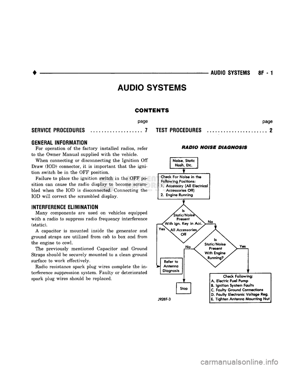
RADIO NOISE DIAGNOSIS
Noise,
Static
Hash,
Etc.
Check
For Noise in
the
Following
Positions:
1.
Accessory (All Electrical
Accessories
Off)
2. Engine Running
Is
'Static/NoiseS
Present
'With
Ign.
Key in Acc.
Yes\^|j
Accessories/
Off
No
Refer
to
Antenna
Diagnosis
f
Stop
No
Is
Static/Noise Present
With Engine
Running?.
Yes
J928F-3
Check
Following:
A.
Electric
Fuel
Pump
B.
Ignition
System
Faults
C.
Faulty Ground Connections
D.
Faulty Electronic Voltage Reg.
E.
Tighten Antenna Mounting Nut
Page 407 of 1502
8F - 4
AUDIO SYSTEMS
• ANTENNA DIAGNOSIS
Turn Ign. Key
to
ACC
Tune
to
Known
Strong AM
Station
f
Check
Antenna Connections
1
1
No
Check
for
Reception Using
A
Test Antenna Repair as
Required*
*Be
Sure
Antenna
is
Properly
Grounded
to
Car.
(Poor
Grounding
of
Antenna
May
Cause
Engine Noise
or
Yes
Static Especially on AM)
Remove
Radio
For
Service
Replace
or
Repair
Defective
Antenna
Or
Lead
in
J928F-4
TIP
OF
MAST
TEST
POINT
RY684
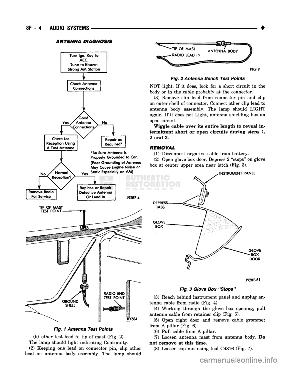
Fig. 1 Antenna Test Points
(b) other test lead to tip of mast (Fig. 2).
The lamp should light indicating Continuity. (2) Keeping one lead on connector pin, clip other
lead on antenna body assembly. The lamp should
-TIP
OF
MAST
•
RADIO LEAD
IN
PR519
Fig.
2 Antenna Bench Test
Points
NOT light. If it does, look for a short circuit in the
body or in the cable probably at the connector.
(3) Remove clip lead from connector pin and clip
on outer shell of connector. Connect other clip lead to
antenna body assembly. The lamp should LIGHT
again. If it does not Light, antenna shielding has an
open circuit.
Wiggle cable over its entire length to reveal in
termittent short or open circuits during steps 1,
2 and 3.
REMOVAL
(1) Disconnect negative cable from battery.
(2) Open glove box door. Depress 2 "stops" on glove
box at center upper area near latch (Fig. 3).
INSTRUMENT
PANEL
DEPRESS
TABS
GLOVE BOX
GLOVE
BOX
DOOR
J928E-51
Fig.
3
Glove
Box
"Stops"
(3) Reach behind instrument panel and unplug an
tenna cable from radio (Fig. 4).
(4) Working through the glove box opening, pull
antenna cable from retainer clip (Fig. 5).
(5) Open right door and remove cable grommet
from A pillar (Fig. 6). (6) Pull cable from A pillar. (7) Loosen antenna mast from antenna body. Do
not remove at this time.
(8) Loosen cap nut using tool C4816 (Fig. 7).
Page 418 of 1502
VEHICLE
SPEED
CONTROL
SYSTEM
8H - 3
GAS
ENGINE
warnings the usi of THE
SPEED
control is NOT recommended when
DRIVING
CONDITIONS
DO not
PERMIT
maintaining
A
constant
SPEED, SUCH
AS
HEAVY
TRAFFIC
©r on
ROADS
THAT ARE
WINDING, ICY, SNOW COVERED
OR
SLIPPERY*
START
ENGINE
r
ACCELERATE
VEHICLE TO DESIRED SPEED
SPEED
CONTROL
ENGAGES
WHEN
mmm is
STARTED
PUSH
ON/OFF
BUTTON
TO "ON"
POSITION.
E
FAULTY
ELECTRICAL CIRCUIT*
SPEED
CONTROL ENGAGES
WITHOUT
PUSHING
THE
"SET/DECEL"
BUTTON
PUSH
AND
RELEASE
"SET/DECEL'
'
BUTTON
FAULTY
ELECTRICAL CIRCUIT* DEFECTIVE SERVO
i
DEFECTIVE SERVO
REMOVE
FOOT
FROM
ACCELERATOR.
SPEED
SHOULD
BE
CONTROLLED
T
1
i
1
*
NO
WEED
CONTROL
WHEN
SET/DECEL
BUTTON IS
PRESSED
AND RELEASED
HUNTING
SURGE
OR
SPEED
VARIATIONS AT
LOW
SPEEDS
EXCESSIVE
SAG
ON
HILLS
OR
IN
TRAILER TOWING
SPEED
SETTING AFTER
LOCK-IN,
TOO
HIGH
C3«t LOW
4 *
FUSE
BLOWN
LOCK-UP
TORQUE CONVERTER
ROUGHNESS
ENGINE
PERFORMANCE
VACUUM LEAK
# f
t f
NO
VACUUM
AT
SERVO
AMPLIFICATION
OF ENGINE
SURGE
VACUUM
LEAK
DEFECTIVE SERVO
1
f
it
t
t
SPEED
CONTROL
THROTTLE
CABLE
DISCONNECTED
DEFECTIVE SERVO
EXCESSIVE
LOAD
MAY
REQUIRE MANUAL
ASSISTANCE
ON
HILLS DEFECTIVE
CABLE
i
f
f • *
IMPROPER
STOP LAMP
AND
SPEED CONTROL SWITCH ADJUSTMENT DEFECTIVE
CABLE
DEFECTIVE VACUUM
RESERVOIR
(CHECK VALVE) DEFECTIVE
VACUUM RESERVOIR
1
f
*
FAULTY
ELECTRICAL CIRCUIT* DEFECTIVE
ENGINE
CONTROLLER
DEFECTIVE SERVO
* TESTS AND
ADJUSTMENTS
ARE DESCRIBED
IN
APPROPRIATE
SECTION
OF SERVICE
MANUAL.
DEFECTIVE VACUUM
RESERVOIR
J918H-7
Page 422 of 1502
•
VEHICLE
SPEED
CONTROL SYSTEM
8H - 7
TEST
PROCEDURES
INDEX
page
Checking
for
Diagnostic
Trouble
Code
7
General
Information
7
Inoperative
System
7
Road
Test
7
Speed
Control
Cable Adjustment—Diesel Engine
. 9
Speed
Control
Cable
Attachment
10
GENERAL
INFORMATION
Before starting diagnosis and repair procedures for
a speed control malfunction, verify that the speed
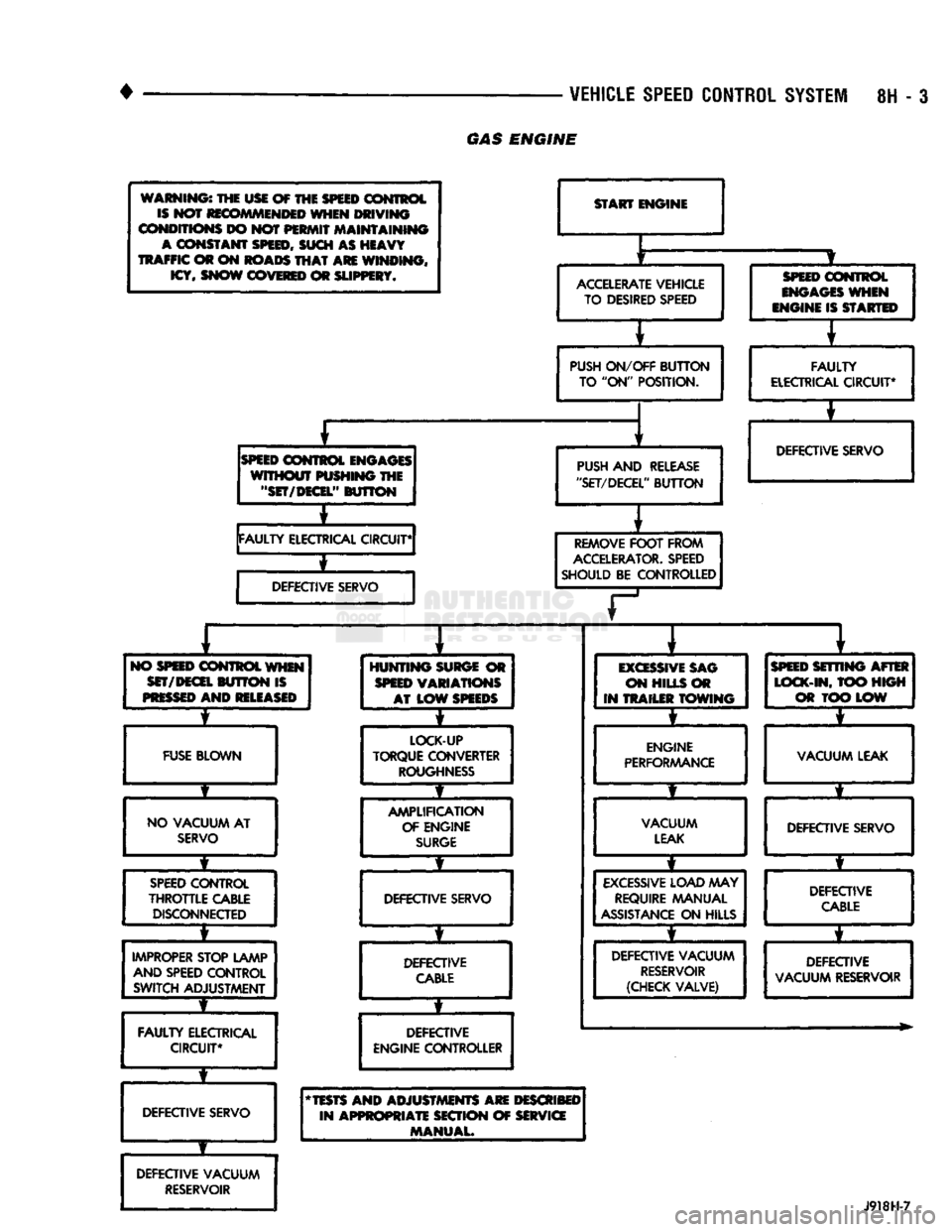
control wire harness is properly connected to all con nectors. Refer to Diagnosis Chart.
ROAD
TEST
Road test vehicle to verify reports of speed control
system malfunction. The road test should include at
tention to the speedometer. Speedometer operation should be smooth and without flutter at all speeds. Flutter in the speedometer indicates a problem
which might cause surging in the speed control sys
tem. The cause of any speedometer deficiencies should be corrected before proceeding.
INOPERATIVE SYSTEM
If road test verifies a system problem and the
speedometer operates properly, check for:
• loose electrical and vacuum connections at the
servo.
• check for correct installation of the vacuum check
valve in the hose from servo to vacuum source (Gas
Engine Only). The word VAC on the valve must
point toward the vacuum source. • corrosion that should be removed from electrical
terminals and a light coating of Mopar Multi-Pur
pose Grease, or equivalent, applied. • secure attachment of both ends of speed control ca
ble.
CHECKING
FOR DIAGNOSTIC TROUBLE CODE
(1) When trying to verify a speed control system
electrical problem, use a DRB II Scan Tool to find
the cause. Refer to Powertrain Diagnostic Procedures manual. If the DRBII is not available, the Diagnostic Trou
ble Code (DTC) may be determined with the follow ing method: (a) With key inserted in ignition switch, cycle
switch to ON position 3 times. On third cycle, leave
switch in ON position. (b) After switch has been cycled 3 times, observe
Malfunction Indicator Lamp (CHECK ENGINE) on instrument cluster. If a DTC is present, the code
page
Speed
Control
Cable Attachment—Servo
10
Stop Lamp Switch Test
9
Vacuum Supply Test
....................... 9
Vehicle Speed
Control
Switch Test
. 9
Vehicle Speed
Control
System
Electrical
Tests
... 7
Vehicle Speed Sensor Test
7
will be displayed in a series of flashes representing
digits.
Three flashes in rapid succession, a slight
pause, then 4 flashes in rapid succession would in dicate DTC 34.
(2) If a DTC 34 is observed, perform the tests in
the sections Electrical Tests at Servo and Electrical
Tests at Powertrain Control Module.
If a DTC 15 is observed, perform the test for a
faulty Vehicle Speed Sensor.
(3) If a fault code 11 is observed (Diesel only), per
form the test for a faulty engine speed sensor. Refer
to the Powertrain Diagnostics Procedures Manual.
(4) Correct any problems found when performing
these tests and recheck for DTC if changes were made.
VEHICLE SPEED SENSOR TEST
For testing of the Vehicle Speed Sensor and related
components refer to the Powertrain Diagnostic Proce
dures manual.
VEHICLE SPEED CONTROL SYSTEM ELECTRICAL
TESTS
Vehicle speed control systems may be tested using
two different methods. One involves the use of the DRBII Scan Tool. If this test method is desired,
please refer to the Powertrain Diagnostic Procedures manual. The other test method uses a voltmeter. The volt
meter method is described in the following tests.
If any information is needed concerning wiring, re
fer to Group 8W - Wiring Diagrams.
CAUTION:
When test probing
for
voltage
or
continuity
at
electrical
connectors, care must
be
taken
not
to
damage connector, terminals,
or
seals.
If
these components
are
damaged,
intermittent
or
complete system
failure
may
occur.
ELECTRICAL
TESTS
AT
SERVO
(1) Turn ignition switch to ON position.
(2) Push speed control switch to ON position.
(3) Connect the negative lead of a voltmeter to a
good chassis ground near the servo.
Page 423 of 1502
8H - 8
VEHICLE SPEED CONTROL SYSTEM
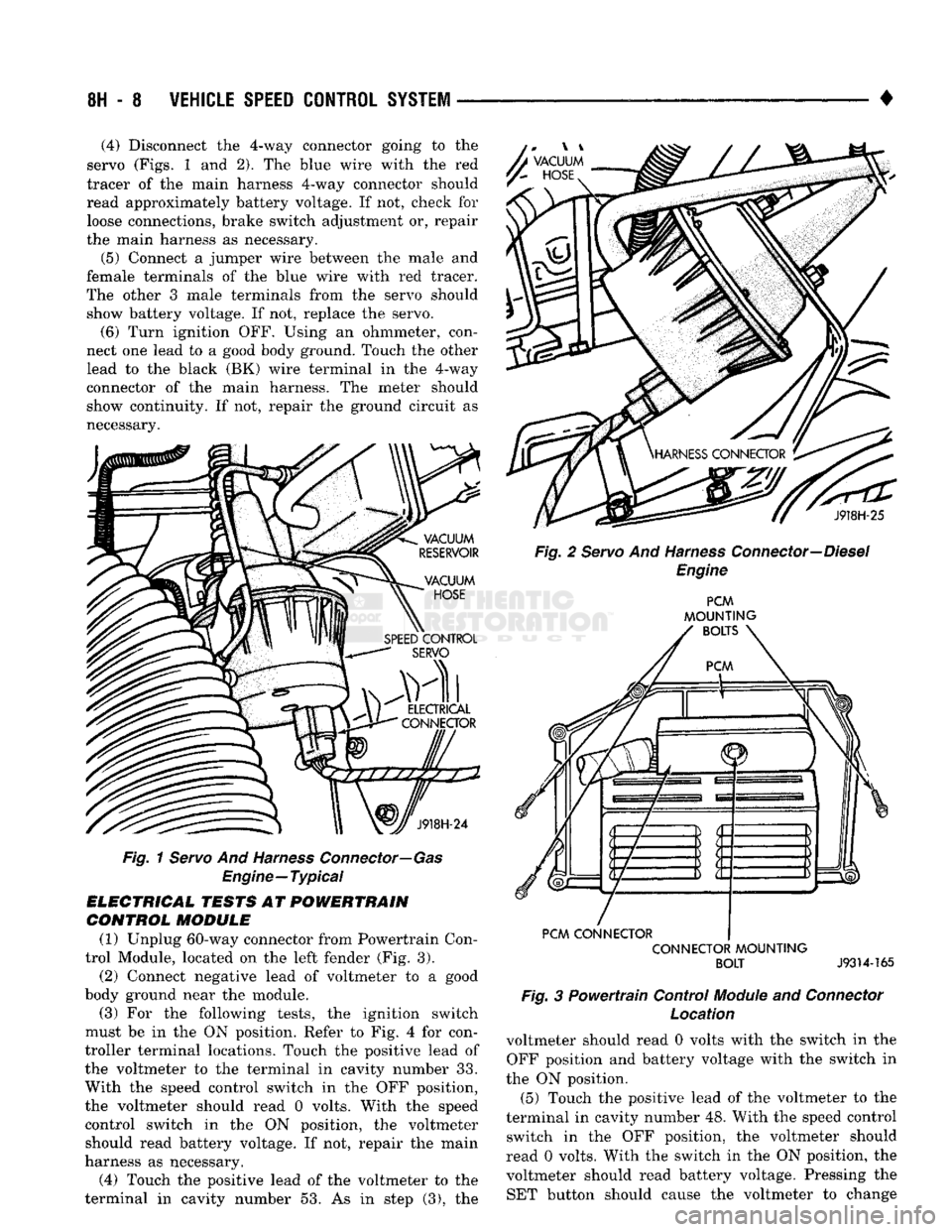
• (4) Disconnect the 4-way connector going to the
servo (Figs. 1 and 2), The blue wire with the red
tracer of the main harness 4-way connector should
read approximately battery voltage. If not, check for loose connections, brake switch adjustment or, repair
the main harness as necessary.
(5) Connect a jumper wire between the male and
female terminals of the blue wire with red tracer.
The other 3 male terminals from the servo should show battery voltage. If not, replace the servo. (6) Turn ignition OFF. Using an ohmmeter, con
nect one lead to a good body ground. Touch the other
lead to the black (BK) wire terminal in the 4-way
connector of the main harness. The meter should
show continuity. If not, repair the ground circuit as
necessary. A
VACUUM
y~
HOSE
J918H-24
Fig.
1 Servo And Harness Connector—Gas
Engine—Typical
ELECTRICAL TESTS AT POWERTRAIN CONTROL MODULE
(1) Unplug 60-way connector from Powertrain Con
trol Module, located on the left fender (Fig. 3).
(2) Connect negative lead of voltmeter to a good
body ground near the module. (3) For the following tests, the ignition switch
must be in the ON position. Refer to Fig. 4 for con
troller terminal locations. Touch the positive lead of
the voltmeter to the terminal in cavity number 33.
With the speed control switch in the OFF position,
the voltmeter should read 0 volts. With the speed
control switch in the ON position, the voltmeter should read battery voltage. If not, repair the main
harness as necessary.
(4) Touch the positive lead of the voltmeter to the
terminal in cavity number 53. As in step (3), the J918H-25
Fig. 2 Servo And Harness Connector—Diesel Engine PCM
MOUNTING
BOLTS
PCM CONNECTOR CONNECTOR MOUNTING BOLT
J9314-165
Fig.
3 Powertrain Control
Module
and
Connector
Location
voltmeter should read 0 volts with the switch in the OFF position and battery voltage with the switch in
the ON position. (5) Touch the positive lead of the voltmeter to the
terminal in cavity number 48. With the speed control switch in the OFF position, the voltmeter should
read 0 volts. With the switch in the ON position, the voltmeter should read battery voltage. Pressing the SET button should cause the voltmeter to change
Page 424 of 1502
![DODGE TRUCK 1993 Service Repair Manual
VEHICLE
SPEED
CONTROL SYSTEM
8H - 9
rain
oooooooooo
1 10,
.oooooooooo
\21 30
„. \£] 50 x
OOOOOOOOOO OOOOOOOOOO^
11
20
OOOOOOOOOO
51
31 1 6ooooooooo60y/ Tratr
TJKT
RR8HC DODGE TRUCK 1993 Service Repair Manual
VEHICLE
SPEED
CONTROL SYSTEM
8H - 9
rain
oooooooooo
1 10,
.oooooooooo
\21 30
„. \£] 50 x
OOOOOOOOOO OOOOOOOOOO^
11
20
OOOOOOOOOO
51
31 1 6ooooooooo60y/ Tratr
TJKT
RR8HC](/manual-img/12/56922/w960_56922-423.png)
VEHICLE
SPEED
CONTROL SYSTEM
8H - 9
rain
oooooooooo
1 10,
.oooooooooo
\21 30
„. \£] 50 x
OOOOOOOOOO OOOOOOOOOO^
11
20
OOOOOOOOOO
51
31 1 6ooooooooo60y/ Tratr
TJKT
RR8HC7
Fig.
4 Powertrain Control Module 60-Way Connector
Shown from Terminal End
from battery voltage to 0 volts for as long as the switch is held. If not, perform the speed control
switch test. If the switch is not at fault, then check
the main harness and repair as necessary.
(6) Touch the positive lead of the voltmeter to the
terminal in cavity number 50. The voltmeter should read 0 volts with the speed control switch in either
the OFF or ON position. With switch in either RE SUME or SET position, the voltmeter should read
battery voltage. If not, perform the speed control switch test. If the switch is not at fault, then check
the main harness and repair as necessary.
(7) Touch the positive lead of the voltmeter to the
terminal in cavity number 49. The voltmeter should read 0 volts with the switch in the OFF position.
With the switch in the ON position, the voltmeter should read battery voltage. The voltmeter will con
tinue to read battery voltage when either the SET or
RESUME switch is pressed. If not, perform the speed control switch test. If the switch is not at fault, then
check the main harness and repair as necessary . (8) Turn key OFF. Using an ohmmeter, connect
one lead to a good body ground and touch the other
lead to the terminal in cavity number 29. With the
brake pedal released, the meter should show continu ity. When the pedal is depressed, the meter should
show open circuit.
VEHICLE
SPEED
CONTROL SWITCH TEST
To check the switch, remove the switch from its
mounting position. Use an ohmmeter and refer to the
Switch Continuity Chart to determine if continuity is
correct. If there is no continuity at any one of the
switch positions, replace the switch.
STOP
LAMP SWITCH TEST
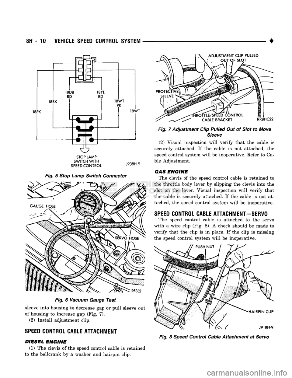
(1) Disconnect connector at stop lamp switch. Us
ing an ohmmeter, continuity may be checked at
switch side of connector as follows (Fig. 5): (a) With brake pedal released, there should be:
• continuity between black (BK) and white with
pink tracer (WT/PK) wires
• continuity between yellow with red tracer (YL/RD) and dark blue with red tracer (DB/RD) wires
• No continuity between pink (PK) and white (WT)
wires.
SPEED CONTROL SWITCH CONTINUITY
CHART
CONNECTOR
TERMINAL
END
JE
El
SWITCH
SPEED
CONTROL
SWITCH
CONTINUITY
SWITCH!
rea?!®^
CONTINUITY
BETWEEN
OFF PIN 1
AND PIN 4
ON PIN
1 AND PIN 4
PIN 1
AND PIN 2
PIN
2 AND PIN 4
ON
AND
SET PIN
1
AN D
PIN 2
ON
AND
RESUME PIN
1 AND PIN 3
J928H-4
(b) With brake pedal depressed, there should be:
• continuity between pink (PK) and white (WT)
wires.
• No continuity between black (BK) and white with
pink tracer (WT/PK) wires.
• No continuity between yellow with red tracer (YL/
RD) and dark blue with red tracer (DB/RD) wires. (2) If the above results are not obtained, the stop
lamp switch is defective or out of adjustment.
Stop lamp switch adjustment is detailed in Group 5 -
Brakes.
VACUUM SUPPLY TEST
(1) Disconnect vacuum hose at the servo and in
stall a vacuum gauge in the hose (Fig. 6). (2) Start engine and observe gauge at idle. Vac
uum gauge should read at least ten inches of mer
cury. (3) If vacuum does not meet this requirement,
check for vacuum leaks or poor engine performance.
SPEED
CONTROL
CABLE
ADJUSTMENT-DIESEL
ENGINE
(1) The gap between the end of the slot on the ca
ble and the bellcrank pin must be as small as possi
ble (0 to 1mm) without moving the throttle. If gap is not correct, remove adjustment clip. Push protective
Page 425 of 1502
8H
- 10
VEHICLE
SPEED
CONTROL
SYSTEM
•
18PK ADJUSTMENT CLIP PULLED
OUT
OF
SLOT
18WT
STOP LAMP
SWITCH
WITH
SPEED
CONTROL
J938H-9
Fig.
5
Stop
Lamp
Switch
Connector
Fig.
6
Vacuum
Gauge
Test
sleeve into housing to decrease gap or pull sleeve out
of housing to increase gap (Fig. 7). (2) Install adjustment clip.
SPEED
CONTROL CABLE ATTACHMENT
DIESEL
ENGINE
(1) The clevis of the speed control cable is retained
to the bellcrank by a washer and hairpin clip.
-TfiROTTLE/SPEED CONTROL
CABLE
BRACKET
RR8HC22
Fig.
7 Adjustment Clip
Pulled
Out of
Slot
to
Move
Sleeve
(2) Visual inspection will verify that the cable is
securely attached. If the cable is not attached, the
speed control system will be inoperative. Refer to Ca
ble Adjustment. GAS ENGINE
The clevis of the speed control cable is retained to
the throttle body lever by slipping the clevis into the slot on the lever. Visual inspection will verify that
the cable is securely attached. If the cable is not at
tached, the speed control system will be inoperative.
SPEED
CONTROL CABLE ATTACHMENT-SERVO
The speed control cable is attached to the servo
with a wire clip (Fig. 8). A check should be made to verify that the clip is in place. If the clip is missing
the speed control system will be inoperative.
HAIRPIN CLIP
/ J918H-9
Fig.
8
Speed
Control Cable Attachment at
Servo