1993 DODGE TRUCK check engine
[x] Cancel search: check enginePage 256 of 1502
•
CLUTCH
6 - 3 Check condition of the clutch before installation. A
warped cover or diaphragm spring will cause grab and incomplete release or engagement.
Be careful when handling the cover and disc. Im
pact can distort the cover, diaphragm spring, release
fingers and the hub of the clutch disc.
Use an alignment tool when positioning the disc on
the flywheel. The tool prevents accidental misalign ment which could result in cover distortion and disc
damage.
A frequent cause of clutch cover distortion (and
consequent misalignment) is improper bolt tighten
ing. To avoid warping the cover, tighten the bolts al
ternately (in a diagonal pattern) and evenly (2-3
threads at a time) to specified torque.
Clutch
Housing
Misalignment And Runout Clutch housing alignment is important to proper
operation. The housing bore maintains alignment be
tween the crankshaft and transmission input shaft.
Misalignment can cause noise, incomplete clutch
release and chatter. It can also result in premature
wear of the pilot bearing, cover release fingers and
clutch disc. In severe cases, misalignment can also cause premature wear of the transmission input
shaft and bearing.
Housing face misalignment is generally caused by
incorrect seating on the engine or transmission, loose
housing bolts, missing alignment dowels or housing damage. Infrequently, misalignment may also be
caused by housing mounting surfaces that are not
parallel. If housing misalignment is suspected, housing bore
and face runout can be checked with a dial indicator
as described in the following two procedures:
MEASURING
CLUTCH HOUSING BORE
RUNOUT
(1) Remove the clutch housing and strut.
(2) Remove the clutch cover and disc.
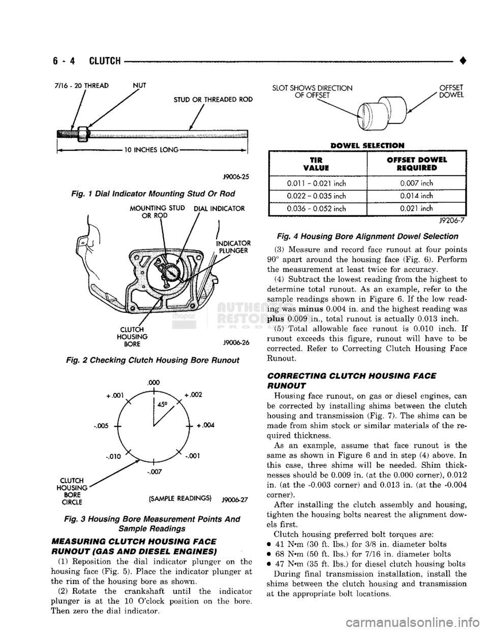
(3) Replace one of the flywheel bolts with a 7/16-20
threaded rod that is 10 in. (25.4 cm) long (Fig. 1).
The rod will be used to mount the dial indicator.
(4) Remove the release fork from the clutch hous
ing. (5) Reinstall the clutch housing. Tighten the hous
ing bolts nearest the alignment dowels first. (6) Mount the dial indicator on the threaded rod
and position the indicator plunger on the surface of
the clutch housing bore (Fig. 2).
(7) Rotate the crankshaft until the indicator
plunger is at the top center of the housing bore. Zero the indicator at this point.
(8) Rotate the crankshaft and record the indicator
readings at eight points (45° apart) around the bore (Fig. 3). Repeat the measurement at least twice for
accuracy. (9) Subtract each reading from the one 180° oppo
site to determine magnitude and direction of runout.
Refer to Figure 3 and following example.
Bore runout example: 0.000 - (-0.007) = 0.007 in. + 0.002 - (-0.010) = 0.012 in.
+ 0.004 - (-0.005) = 0.009 in.
-0.001 -
(
+ 0.001) = -0.002 in. (= 0.002 inch)
In the above example, the largest difference is
0.012 in. and is called the total indicator reading
(TIR).
This means that the housing bore is offset
from the crankshaft centerline by 0.006 in. (which is 1/2 of 0.012 in.).
On gas engines, the acceptable maximum TIR for
housing bore runout is 0.010 inch. If measured TIR is more than 0.010 in. (as in the example), bore runout
will have to be corrected with offset dowels. Offset dowels are available in 0.007, 0.014 and 0.021 in.
sizes for this purpose (Fig. 4). Refer to Correcting
Housing Bore Runout for dowel installation.
On diesel engines, the acceptable maximum
TIR for housing bore runout is 0.015 inch. How
ever, unlike gas engines, offset dowels are not available to correct runout on diesel engines. If
bore runout exceeds the stated maximum on a diesel engine, it may be necessary to replace ei
ther the clutch housing, or transmission adapter
plate.
CORRECTING CLUTCH HOUSING BORE
RUNOUT
(GAS
ENGINE
ONLY)
On gas engine vehicles, clutch housing bore runout
is corrected with offset dowels. However, if bore
runout exceeds 0.015 in. TIR on a diesel equipped model, the clutch housing, or transmission adapter
plate may have to be replaced. Offset dowels are not available for diesel models.
The dial indicator reads positive when the plunger
moves inward (toward indicator) and negative when it moves outward (away from indicator). As a result,
the lowest or most negative reading determines the
direction of housing bore offset (runout).
In the sample readings shown in Figure 3 and in
step (7) above, the bore is offset toward the 0.010
inch reading. To correct this, remove the housing and
original dowels. Then install the new offset dowels in
the direction needed to center the bore with the crankshaft centerline.
In the example, TIR was 0.012 inch. The dowels
needed for correction would have an offset of 0.007
in. (Fig. 4).
Install the dowels with the slotted side facing out
so they can be turned with a screwdriver. Then in
stall the housing, remount the dial indicator and
check bore runout again. Rotate the dowels until the
TIR is less than 0.010 in. if necessary.
If a TIR of 0.053 in. or greater is encountered, it
may be necessary to replace the clutch housing.
Page 257 of 1502
e - 4
CLUTCH
•
7/16 - 20
THREAD
NUT
10 INCHES LONG J9006-25
CLUTCH
HOUSING
BORE
J9006-26
Fig.
2 Checking Clutch Housing Bore Runout
.000
CLUTCH
HOUSING
qroe {Smm READINGS) J9006-27
Fig.
3
Housing
Bore Measurement Points And Sample Readings
MEASURING
CLUTCH
HOUSING FACE
RUNOUT (GAS AND DIESEL ENGINES) (1) Reposition the dial indicator plunger on the
housing face (Fig. 5). Place the indicator plunger at
the rim of the housing bore as shown.
(2) Rotate the crankshaft until the indicator
plunger is at the 10 O'clock position on the bore.
Then zero the dial indicator.
SLOT SHOWS DIRECTION OFFSET
DOWEL
DOWEL SELECTION
TIR
VALUE OFFSET DOWEL
REQUIRED
0.011
-0.021
inch
0.007
inch
0.022
-
0.035
inch
0.014
inch
0.036
-
0.052
inch
0.021
inch
J9206-7
Fig.
4
Housing
Bore
Alignment
Dowel
Selection
(3)
Measure and record face runout at four points
90° apart around the housing face (Fig. 6). Perform
the measurement at least twice for accuracy.
(4)
Subtract the lowest reading from the highest to
determine total runout. As an example, refer to the
sample readings shown in Figure 6. If the low read
ing was minus
0.004
in. and the highest reading was
plus
0.009
in., total runout is actually
0.013
inch.
(5)
Total allowable face runout is 0.010 inch. If
runout exceeds this figure, runout will have to be
corrected. Refer to Correcting Clutch Housing Face
Runout.
CORRECTING CLUTCH HOUSING FACE
RUNOUT
Housing face runout, on gas or diesel engines, can
be corrected by installing shims between the clutch
housing and transmission (Fig. 7). The shims can be made from shim stock or similar materials of the re
quired thickness.
As an example, assume that face runout is the
same as shown in Figure 6 and in step (4) above. In
this case, three shims will be needed. Shim thick
nesses should be
0.009
in. (at the
0.000
corner),
0.012
in. (at the
-0.003
corner) and
0.013
in. (at the
-0.004
corner).
After installing the clutch assembly and housing,
tighten the housing bolts nearest the alignment dow els first.
Clutch housing preferred bolt torques are:
• 41 N-m (30 ft. lbs.) for 3/8 in. diameter bolts
• 68 Nnn (50 ft. lbs.) for 7/16 in. diameter bolts
• 47 Nth (35 ft. lbs.) for diesel clutch housing bolts During final transmission installation, install the
shims between the clutch housing and transmission at the appropriate bolt locations.
Page 259 of 1502
6 - 6
CLUTCH
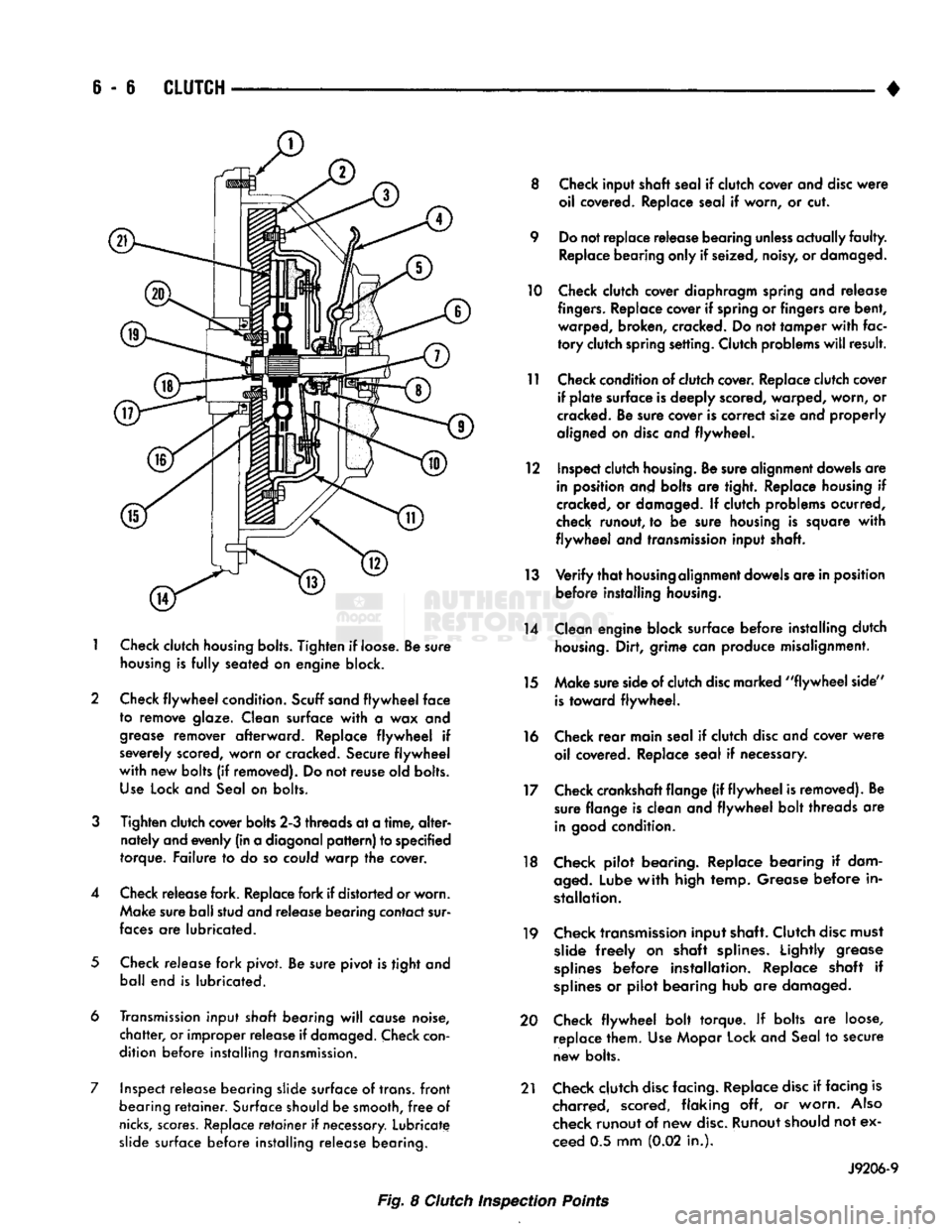
1
Check
clutch
housing bolts.
Tighten
if loose. Be sure
housing
is
fully
seated on engine block.
2 Check
flywheel
condition.
Scuff sand
flywheel
face
to remove glaze. Clean surface
with
a wax and
grease
remover afterward. Replace
flywheel
if
severely scored, worn or cracked. Secure
flywheel
with
new bolts (if removed). Do not reuse old bolts.
Use
Lock and Seal on bolts.
3
Tighten clutch cover bolts 2-3 threads at a
time,
alter
nately and evenly (in a diagonal
pattern)
to specified
torque. Failure to do so could warp the cover.
4 Check release fork. Replace fork if distorted or worn. Make sure ball stud and release bearing contact sur
faces
are lubricated.
5
Check release fork pivot. Be sure pivot is tight and ball end is lubricated.
6 Transmission input
shaft
bearing
will
cause noise,
chatter,
or improper release if
damaged.
Check
con
dition before installing transmission.
7 Inspect release bearing slide surface of trans,
front
bearing
retainer.
Surface should be smooth,
free
of
nicks,
scores.
Replace
retainer
if
necessary.
Lubricate slide surface before installing release bearing. 8 Check input shaft seal if clutch cover and
disc
were
oil covered. Replace seal if worn, or cut.
9 Do not replace release bearing
unless
actually
faulty.
Replace bearing only if seized, noisy, or damaged.
10 Check clutch cover diaphragm spring and release
fingers.
Replace cover if spring or fingers are bent, warped, broken, cracked. Do not tamper
with
fac
tory
clutch spring setting. Clutch problems
will
result.
11 Check condition of clutch cover. Replace clutch cover if
plate
surface is deeply scored, warped, worn, or
cracked. Be sure cover is correct size and properly
aligned on
disc
and flywheel.
12 Inspect clutch
housing.
Be sure alignment dowels are in position and bolts are tight. Replace housing if
cracked, or damaged. If clutch problems ocurred,
check runout, to be sure housing is square
with
flywheel
and transmission input shaft.
13
Verify
that
housing
alignment dowels are in position before installing
housing.
14 Clean engine block surface before installing clutch
housing.
Dirt, grime can produce misalignment.
15 Make sure side of clutch
disc
marked
"flywheel
side"
is
toward flywheel.
16 Check
rear
main seal if clutch
disc
and cover
were
oil covered. Replace seal if necessary.
17 Check crankshaft flange (if
flywheel
is removed). Be sure flange is clean and
flywheel
bolt threads are
in
good
condition.
18 Check pilot bearing. Replace bearing if dam
aged.
Lube
with
high temp. Grease before in
stallation.
19 Check transmission input shaft. Clutch
disc
must slide
freely
on shaft splines. Lightly grease
splines
before installation. Replace shaft if
splines
or pilot bearing hub are damaged.
20 Check
flywheel
bolt torque. If bolts are loose, replace them. Use Mopar Lock and Seal to secure
new bolts.
21 Check clutch
disc
facing. Replace
disc
if facing is charred, scored, flaking off, or worn.
Also
check runout of new
disc.
Runout should not ex
ceed 0.5 mm (0.02 in.).
J9206-9
Fig. 8 Clutch Inspection Points
Page 262 of 1502
•
CLUTCH
6 - 9 CLUTCH GRAB/CHATTER
Condition
Found
Cause
T
Correction
1.
Clutch
disc
facing covered
with
oil, grease, or clutch fluid. a) Oil leak at
rear
main or input
shaft seal.
b) Too much grease applied to
splines
or
disc
and input shaft. a) Correct leak and replace
disc
(do not clean and reuse the
disc).
b) Apply lighter grease coating to splines and replace
disc
(do not clean and reuse the disc).
2. Clutch
disc
and/or cover warped, or
disc
facings
exhibit
unusual
wear or appear to be
wrong type. Incorrect or substandard parts.
Replace
disc
and/or cover
with
correct parts.
3. Clutch master or slave cylinder plunger dragging-binding. a) Master or slave cylinder
components worn or corroded. a) Replace both cylinders as
assembly
(and reservoir).
4. No
fault
found
with
clutch
components.
a) Problem actually
related
to
suspension
or driveline
component.
b) Engine
related
problem. a)
Further
diagnosis
required.
Check
engine/transmission
mounts,
propeller shafts and U-joints, tires,
suspension
attaching parts and other
driveline components as needed.
b) Check EFI and igniton
systems.
5.
Partial
engagement of clutch
disc
(one side worn-opposite
side
glazed and lightly worn). a) Clutch pressure
plate
position
setting incorrect or modified.
b) Clutch cover, spring, or release fingers bent, distorted (rough
handling,
improper assembly).
c) Clutch
disc
damaged or distorted.
d) Clutch misalignment. a) Replace clutch cover and
disc.
b) Replace clutch cover and
disc.
c) Replace
disc.
d) Check alignment and runout of flywheel,
disc,
or cover and/or clutch
housing.
Correct as
necessary.
J9006-23
Page 264 of 1502
•
CLUTCH
S - 11
CLUTCH
SERVICE
INDEX
page
Clutch
Cover
and
Disc
Installation—All
11
Clutch
Cover
and
Disc
Removal—All
. 11
Clutch
Housing
Installation
13
Clutch
Housing
Removal
12
Clutch
Linkage
Service
14
CLUTCH
COVER
AND
DISC
REMOVAL—ALL
(1) Raise vehicle.
(2) Remove transmission and remove transfer case
if equipped. Refer to Group 21 for procedures. (3) Remove clutch housing from engine.
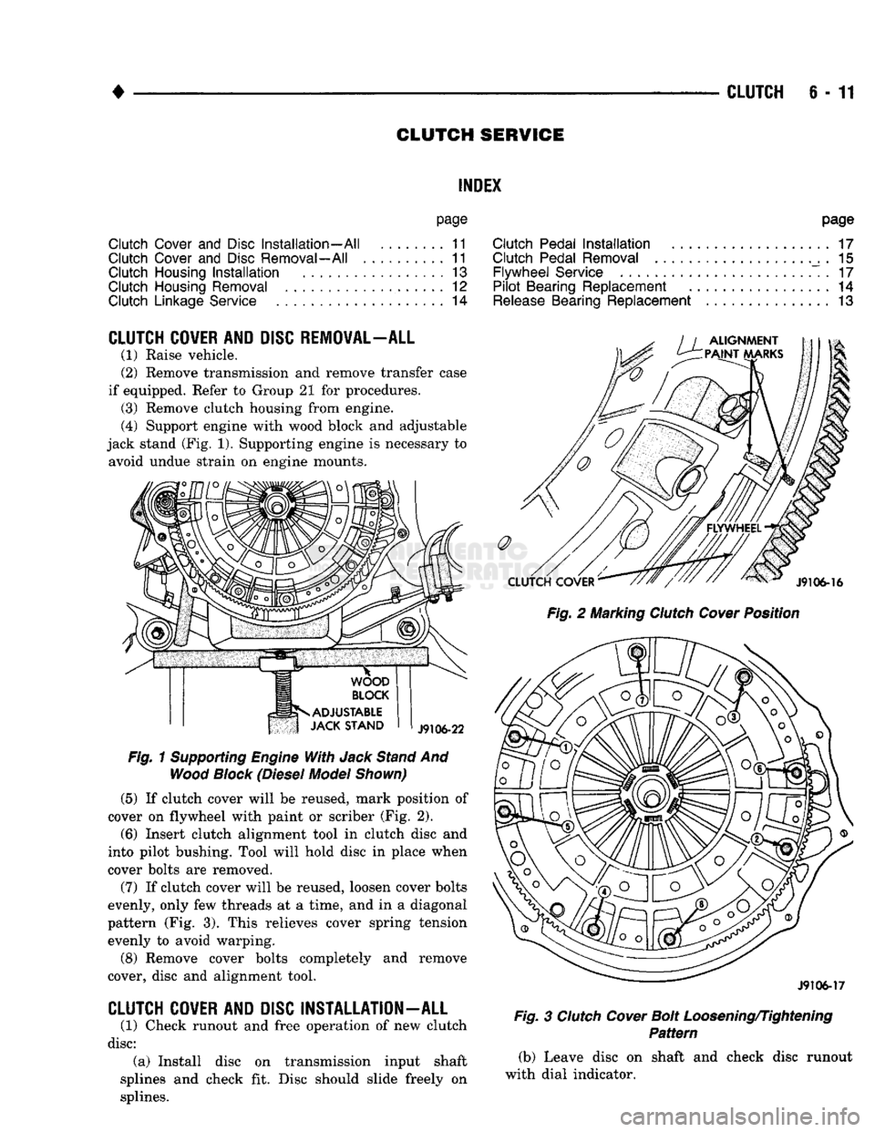
(4) Support engine with wood block and adjustable
jack stand (Fig. 1). Supporting engine is necessary to avoid undue strain on engine mounts.
Fig.
1
Supporting
Engine
With
Jack
Stand
And
Wood
Block
(Diesel
Model
Shown)
(5)
If clutch cover will be reused, mark position of
cover on flywheel with paint or scriber (Fig. 2).
(6)
Insert clutch alignment tool in clutch disc and
into pilot bushing. Tool will hold disc in place when
cover bolts are removed.
(7) If clutch cover will be reused, loosen cover bolts
evenly, only few threads at a time, and in a diagonal
pattern (Fig. 3). This relieves cover spring tension evenly to avoid warping.
(8) Remove cover bolts completely and remove
cover, disc and alignment tool.
CLUTCH
COVER
AND
DISC
INSTALLATION
-
ALL
(1) Check runout and free operation of new clutch
disc:
(a) Install disc on transmission input shaft
splines and check fit. Disc should slide freely on
splines.
page
Clutch
Pedal
Installation
17
Clutch
Pedal
Removal
. 15
Flywheel
Service
. 17
Pilot
Bearing
Replacement
14
Release
Bearing
Replacement
13
Fig.
2 Marking
Clutch
Cover
Position
J9106-17
Fig.
3
Clutch
Cover
Bolt
Loosening/Tightening
Pattern
(b) Leave disc on shaft and check disc runout
with dial indicator.
Page 265 of 1502
6-12
CLUTCH
(c) Position indicator plunger about 1/4 inch from
outer edge of disc facing.
(d) Runout should not exceed 0.5 mm (0.020 in.).
Obtain another clutch disc if runout exceeds this
limit.
(2) Lubricate crankshaft pilot bearing with Mopar
high temperature bearing grease.
(3) Insert clutch alignment tool in clutch disc hub,
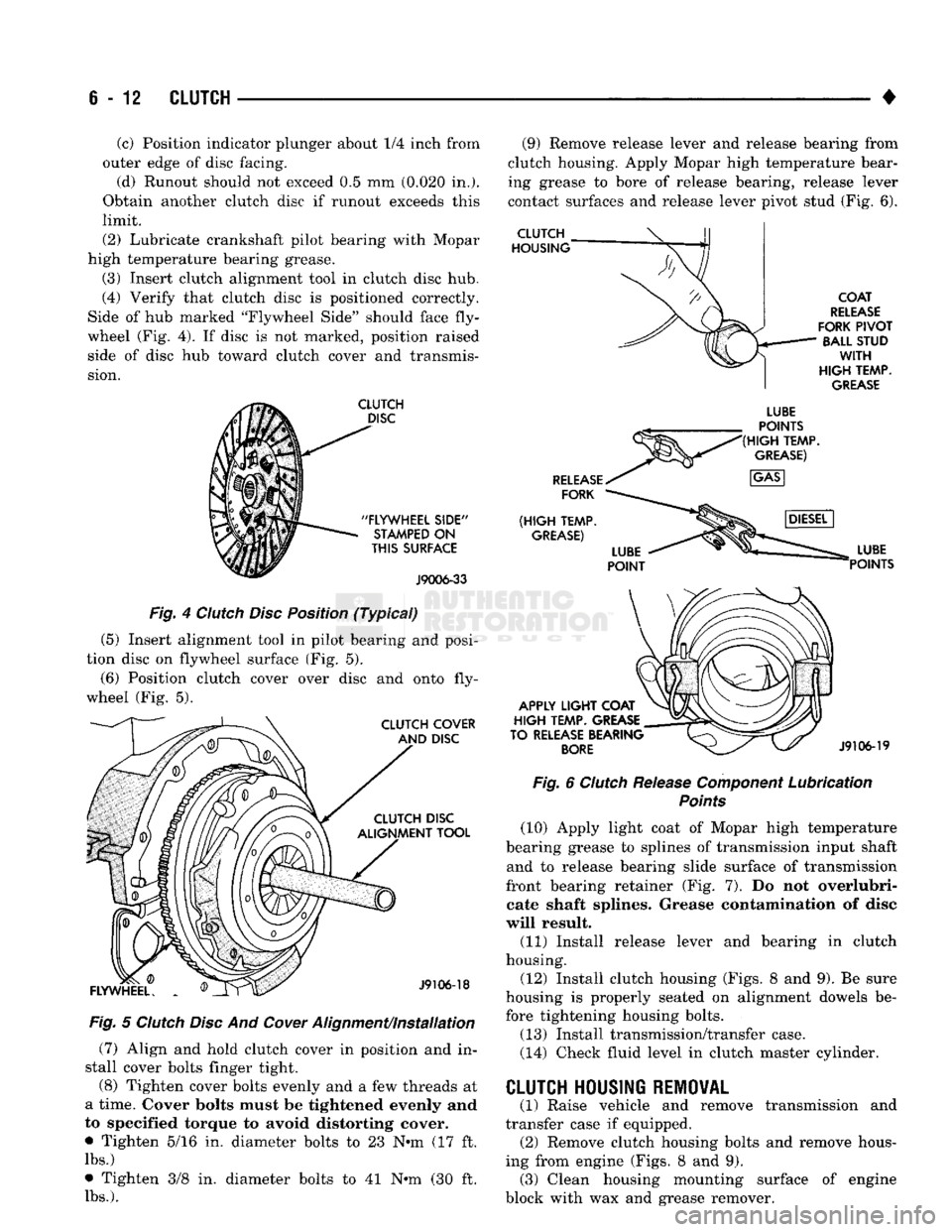
(4) Verify that clutch disc is positioned correctly.
Side of hub marked "Flywheel Side" should face fly
wheel (Fig. 4). If disc is not marked, position raised side of disc hub toward clutch cover and transmis
sion.
CLUTCH
DISC
"FLYWHEEL
SIDE"
STAMPED
ON
THIS
SURFACE
J9006-33
Fig. 4 Clutch Disc Position (Typical)
(5) Insert alignment tool in pilot bearing and posi
tion disc on flywheel surface (Fig. 5).
(6) Position clutch cover over disc and onto fly
wheel (Fig. 5).
CLUTCH COVER AND DISC CLUTCH DISC
ALIGNMENT TOOL
FLYWHEEL.
J9106-18
Fig. 5 Clutch Disc And
Cower
Alignment/installation (7) Align and hold clutch cover in position and in
stall cover bolts finger tight.
(8) Tighten cover bolts evenly and a few threads at
a time. Cover bolts must be tightened evenly and
to specified torque to avoid distorting cover.
• Tighten 5/16 in. diameter bolts to 23 N-m (17 ft.
lbs.)
• Tighten 3/8 in. diameter bolts to 41 N-m (30 ft.
lbs.).
(9) Remove release lever and release bearing from
clutch housing. Apply Mopar high temperature bear
ing grease to bore of release bearing, release lever
contact surfaces and release lever pivot stud (Fig. 6).
CLUTCH
HOUSING
COAT
RELEASE
FORK
PIVOT
BALL STUD
WITH
HIGH
TEMP.
GREASE
RELEASE
FORK
(HIGH
TEMP.
GREASE)
LUBE
POINTS
(HIGH
TEMP.
GREASE)
APPLY
LIGHT
COAT
HIGH
TEMP. GREASE
TO RELEASE BEARING
BORE
LUBE
POINTS
J9106-19
Fig. 6 Clutch Release Component Lubrication
Points
(10) Apply light coat of Mopar high temperature
bearing grease to splines of transmission input shaft and to release bearing slide surface of transmission
front bearing retainer (Fig. 7). Do not overlubri- cate shaft splines. Grease contamination of disc
will result. (11) Install release lever and bearing in clutch
housing.
(12) Install clutch housing (Figs. 8 and 9). Be sure
housing is properly seated on alignment dowels be fore tightening housing bolts.
(13) Install transmission/transfer case.
(14) Check fluid level in clutch master cylinder. transmission and
CLUTCH HOUSING REMOVAL
(1) Raise vehicle and remove
transfer case if equipped. (2) Remove clutch housing bolts and remove hous
ing from engine (Figs. 8 and 9). (3) Clean housing mounting surface of engine
block with wax and grease remover.
Page 270 of 1502

•
CLUTCH
6-17
CLUTCH PEDAL INSTALLATION
(1) Lubricate pedal shaft, pedal shaft bore and all
bushings with Mopar Multi Mileage grease. (2) Insert pedal pin into cylinder push rod. Then
position clutch pedal in support. (3) Slide pedal shaft through clutch pedal bore and
bushings. (4) Install bolt that retains pedal shaft in support.
(5) Secure push rod to pedal pin with wave washer,
flat washer and retaining ring.
FLYWHEEL SERVICE
Inspect the flywheel whenever the clutch disc,
cover and housing are removed for service. Check
condition of the flywheel face, hub, ring gear teeth,
and flywheel bolts. Minor scratches, burrs, or glazing on the flywheel
face can be scuff sanded with 180 grit emery cloth. However, the flywheel should be replaced if the disc
contact surface is severely scored, heat checked,
cracked, or obviously worn. Cleanup of minor flywheel scoring should be per
formed with surface grinding equipment. Remove
only enough material to reduce scoring (approximate
ly 0.001 - 0.003 in.). Heavy stock removal is not rec
ommended. Replace the flywheel if scoring is severe
and deeper than 0.076 mm (0.003 in.). Excessive
stock removal can result in flywheel cracking or
warpage after installation; it can also weaken the flywheel and interfere with proper clutch release. Check flywheel runout if misalignment is sus
pected. Runout should not exceed 0.08 mm (0.003
in.).
Measure runout at the outer edge of the fly
wheel face with a dial indicator. Mount the dial in
dicator on a stud installed in place of one of the
flywheel attaching bolts. Clean the crankshaft flange before mounting the
flywheel. Dirt and grease on the flange surface may cock the flywheel causing excessive runout. Check condition of the flywheel hub and attaching
bolts.
Replace the flywheel if the hub exhibits cracks in the area of the attaching bolt holes. Install new attaching bolts whenever the flywheel
is replaced and use Mopar Lock N' Seal, or Loctite
242 on replacement bolt threads.
Recommended flywheel bolt torques are:
• 75 N»m (55 ft. lbs.) for gas engine flywheels
• 137 N*m (101 ft. lbs.) for diesel flywheels Inspect the teeth on the starter ring gear. If the
teeth are worn or damaged, the flywheel should
be replaced as an assembly. This is the recom mended and preferred method of repair.
In cases where a new flywheel is not readily avail
able,
a replacement ring gear can be installed. How
ever, the following precautions must be observed to
avoid damaging the flywheel and replacement gear.
(a) Mark position of the old gear for alignment
reference on the flywheel. Use a scriber for this
purpose.
(b) Wear protective goggles or approved safety
glasses. Also wear heat resistent gloves when han
dling a heated ring gear. (c) Remove the old gear by cutting most of the
way through it (at one point) with an abrasive cut off wheel. Then complete removal with a cold chisel
or punch. (d) The ring gear is a shrink fit on the flywheel.
This means the gear must be expanded by heating in order to install it. The method of heating and expanding the gear is extremely important. Ev
ery surface of the gear must be heated at the same
time to produce uniform expansion. An oven or
similar enclosed heating device must be used. Tem
perature required for uniform expansion is 325-350° F.
CAUTION:
Never
use an
oxy/acetylene torch
to re
move
the old
gear,
or to
heat
and
expand
a new
gear.
The
high temperature
of the
torch flame
will
cause
localized heating
and
damage
the
flywheel.
In
addition,
using
the
torch
to
heat
a
replacement gear
will
cause uneven heating
and
expansion.
The
torch
flame
will
also
anneal
the
gear
teeth
resulting
in
rapid wear
and
damage
after
installation.
(e) The heated gear must be installed evenly to
avoid misalignment or distortion. A shop press and
suitable press plates should be used to install the
gear if at all possible.
(f) Be sure to wear eye and hand protection.
Heat resistent gloves and safety goggles are needed
for personal safety. Also use metal tongs, vise
grips,
or similar tools to position the gear as necessary for installation.
(g) Allow the flywheel and ring gear to cool
down before installation. Set the assembly on a
workbench and let it cool in normal shop air.
CAUTION:
Do not
use water,
or
compressed
air to
cool
the
flywheel.
The
rapid cooling produced
by
water
or
compressed
air can
distort,
or
crack
the
gear
and
flywheel.
Page 275 of 1502
DIAGNOSIS
PRELIMINARY
CHECKS
ENGINE COOLING SYSTEM OVERHEATING Establish what driving conditions caused the com
plaint. Abnormal loads on the cooling system such as
the following may be the cause:
1.
PROLONGED IDLE, VERY HIGH AMBI
ENT TEMPERATURE, SLIGHT TAIL WIND AT
IDLE, SLOW TRAFFIC, TRAFFIC JAMS, HIGH SPEED OR STEEP GRADES.
Driving techniques that avoid overheating are:
• Idle with A/C off when temperature gauge is at
end of normal range. * Increasing engine speed for more air flow is recom
mended.
2.
TRAILER TOWING: Consult Trailer Towing section of owners manual.
Do not exceed limits.
3.
AIR CONDITIONING; ADD-ON OR AFTER
MARKET: A maximum cooling package should have been or
dered with vehicle if add-on or after market A/C is
SYMPTOM AND ACTION
SYMPTOM
installed. If not, maximum cooling system compo
nents should be installed for model involved per
manufacturer's specifications.
4.
RECENT SERVICE OR ACCIDENT RE
PAIR:
Determine if any recent service has been performed
on vehicle that may effect cooling system. This may
be:
• Engine adjustments (incorrect timing)
• Slipping engine accessory drive belt(s) • Brakes (possibly dragging)
• Changed parts. Incorrect water pump or pump ro
tating in wrong direction due to belt not correctly
routed
• Reconditioned radiator or cooling system refilling (possibly under filled or air trapped in system).
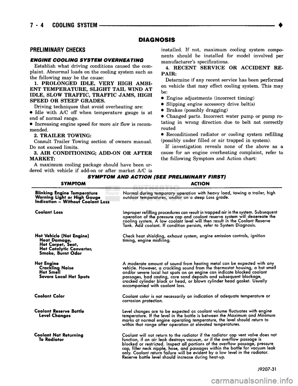
If investigation reveals none of the above as a
cause for an engine overheating complaint, refer to
the following Symptom and Action chart:
PRELIMINARY FIRST) ACTION
Blinking Engine Temperature
Warning Light or High Gauge indication - Without Coolant Loss
Normal during temporary operation
with
heavy load, towing
a
trailer,
high
outdoor temperatures, and/or on
a
steep
Loss
grade.
Coolant Loss
Hot Vehicle (Not Engine) Heat Damage,
Hot Carpet, Seat,
Hot
Catalytic
Converter,
Smoke, Burnt Odor
Hot Engine Crackling Noise Hot Smell
Severe Local Hot Spots
Coolant Color
Coolant Reserve Bottle Level Changes
Coolant Not Returning To Radiator
Improper refilling procedures
can
result
in
trapped air
in
the
system.
Subsequent
operation
of the
pressure cap and coolant reserve system
will
deaereate
the
cooling
system.
A low
coolant
level
will
then result
in the
Coolant Reserve
Tank. Add coolant.
If
condition persists,
refer
to
System
Diagnosis.
Check
heat shielding, exhaust
system,
engine emission controls, ignition
timing, engine misfiring.
A
moderate amount
of
sound from heating
metal
can
be
expected
with
any
vehicle. However,
a
crackling sound from
trie
thermostat
housing,
a hot
smell and/or severe local
hot
spots on
an
engine can indicate blocked coolant
passages,
bad castina, core sand deposits and subsequent blockage,
cracked cylinder block
or
head,
or
blown cylinder head gasket. Usually
accompanied
with
coolant
loss.
Coolant
color is
not
necessarily
an
indication
of
adequate
temperature
or
corrosion
protection.
Level changes
are to be
expected as coolant volume fluctuates
with
engine
temperature.
If the
level
in the
bottle
is
between
the
Maximum and Minimum
marks
at
normal engine operating temperature,
the
level
should
return
to
within
that
range
after
operation
at
elevated temperatures.
Coolant
will
not
return
to the
radiator
if the
radiator cap vent valve does
not
function,
if
an
air
leak destroys vacuum,
or if the
overflow
passage
is
blocked
or
restricted. Inspect
all
portions
of the
overflow
passage,
pressure
cap,
filler
neck nipple, hose, and
passages
within
the
bottle
for
vacuum leak
only. Coolant
return
failure
will
be
evident
by a low
level
in the
radiator.
Reserve
bottle
level
should increase during heat-up.
J9207-31