1993 DODGE TRUCK stop start
[x] Cancel search: stop startPage 751 of 1502
9
- 148 5.9L
(DIESEL) ENGINE
• Make sure the idler gear pin is installed in the lo
cating bore in the cylinder block. (2) Install the pump. Tighten the oil pump mount
ing bolts in two steps and in the sequence shown (Fig. 2).
• Step
1—Tighten
to 5 N«m (44 in. lbs.) torque.
• Step 2-Tighten to 24 N*m (18 ft. lbs.) torque. (3) The back plate on the pump seats against the
bottom of the bore in the cylinder block. When the
pump is correctly installed, the flange on the pump will not touch the cylinder block.
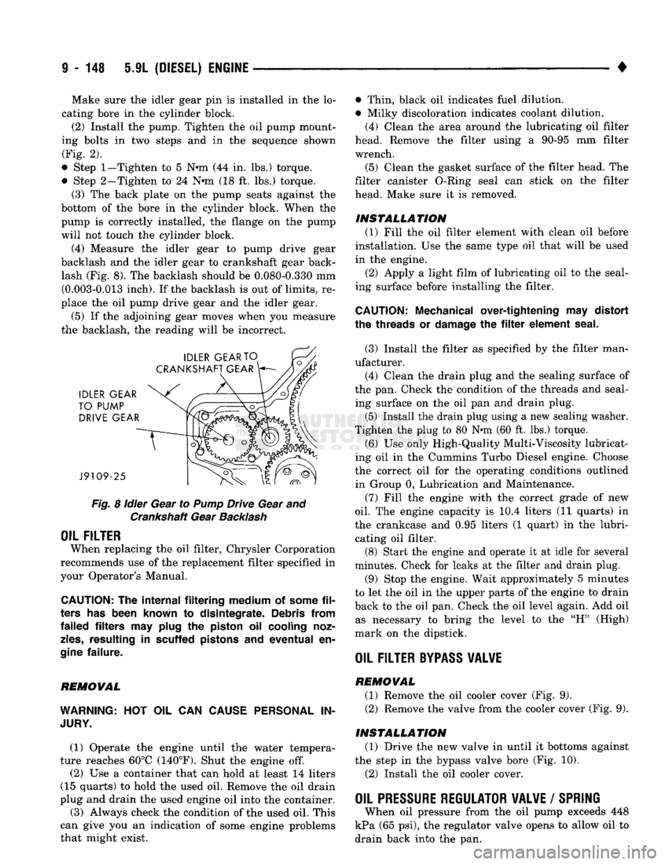
(4) Measure the idler gear to pump drive gear
backlash and the idler gear to crankshaft gear back lash (Fig. 8). The backlash should be 0.080-0.330 mm (0.003-0.013 inch). If the backlash is out of limits, re
place the oil pump drive gear and the idler gear.
(5) If the adjoining gear moves when you measure
the backlash, the reading will be incorrect.
Fig.
8
idler
Gear to
Pump
Drive Gear and Crankshaft Gear
Backlash
OIL FILTER
When replacing the oil filter, Chrysler Corporation
recommends use of the replacement filter specified in
your Operator's Manual.
CAUTION:
The
internal filtering medium
of
some
fil
ters
has
been known
to
disintegrate. Debris from
failed filters
may
plug
the
piston
oil
cooling noz
zles,
resulting
in
scuffed pistons
and
eventual
en
gine
failure.
REMOVAL
WARNING:
HOT OIL CAN
CAUSE PERSONAL
IN
JURY.
(1) Operate the engine until the water tempera
ture reaches 60°C (140°F). Shut the engine off.
(2) Use a container that can hold at least 14 liters
(15 quarts) to hold the used oil. Remove the oil drain
plug and drain the used engine oil into the container.
(3) Always check the condition of the used oil. This
can give you an indication of some engine problems
that might exist. • Thin, black oil indicates fuel dilution.
• Milky discoloration indicates coolant dilution.
(4) Clean the area around the lubricating oil filter
head. Remove the filter using a 90-95 mm filter
wrench.
(5) Clean the gasket surface of the filter head. The
filter canister O-Ring seal can stick on the filter
head. Make sure it is removed.
INSTALLATION (1) Fill the oil filter element with clean oil before
installation. Use the same type oil that will be used
in the engine.
(2) Apply a light film of lubricating oil to the seal
ing surface before installing the filter.
CAUTION:
Mechanical over-tightening
may
distort
the threads
or
damage
the filter
element seal.
(3) Install the filter as specified by the filter man
ufacturer. (4) Clean the drain plug and the sealing surface of
the pan. Check the condition of the threads and seal ing surface on the oil pan and drain plug.
(5) Install the drain plug using a new sealing washer.
Tighten the plug to 80 N-m (60 ft. lbs.) torque.
(6) Use only High-Quality Multi-Viscosity lubricat
ing oil in the Cummins Turbo Diesel engine. Choose
the correct oil for the operating conditions outlined in Group 0, Lubrication and Maintenance.
(7) Fill the enginfe with the correct grade of new
oil.
The engine capacity is i0.4 liters (11 quarts) in
the crankcase and 0.95 liters (1 quart) in the lubri cating oil filter. (8) Start the engine and operate it at idle for several
minutes. Check for leaks at the filter and drain plug.
(9) Stop the engine. Wait approximately 5 minutes
to let the oil in the upper parts of the engine to drain
back to the oil pan. Check the oil level again. Add oil as necessary to bring the level to the "H" (High)
mark on the dipstick.
OIL FILTER
BYPASS
VALWE
REMOVAL
(1) Remove the oil cooler cover (Fig. 9). (2) Remove the valve from the cooler cover (Fig. 9).
INSTALLATION (1) Drive the new valve in until it bottoms against
the step in the bypass valve bore (Fig. 10).
(2) Install the oil cooler cover.
OIL PRESSURE REGULATOR VALVE
/
SPRING
When oil pressure from the oil pump exceeds 448
kPa (65 psi), the regulator valve opens to allow oil to
drain back into the pan.
Page 854 of 1502
•
FUEL SYSTEM
14 - 35
SENSOR
RETURN—PCM
INPUT
Sensor Return provides a low noise ground refer
ence for all system sensors.
THROTTLE POSITION
SENSOR
(TPS)-PCM
INPUT
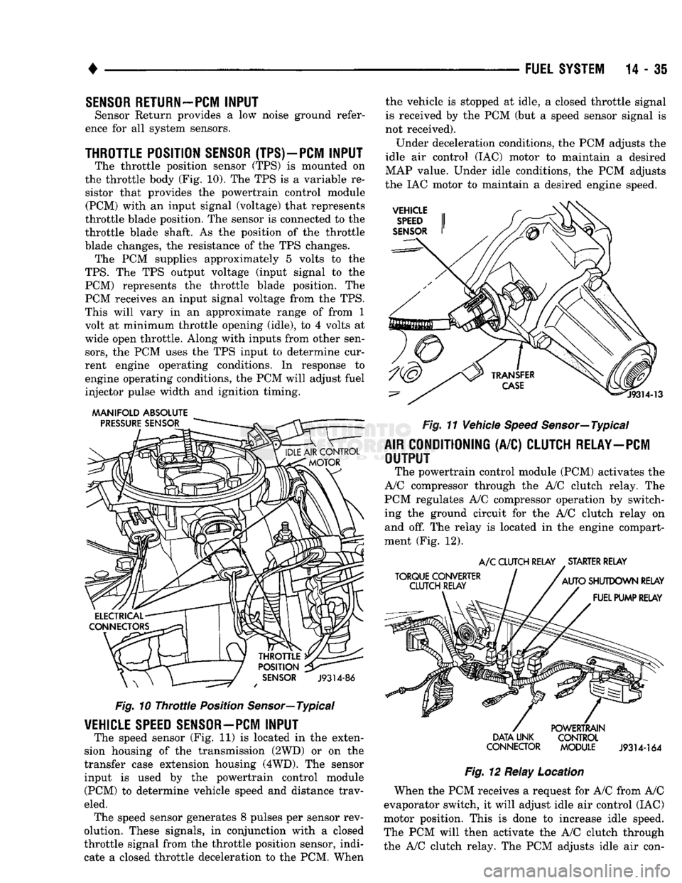
The throttle position sensor (TPS) is mounted on
the throttle body (Fig. 10). The TPS is a variable re sistor that provides the powertrain control module (PCM) with an input signal (voltage) that represents
throttle blade position. The sensor is connected to the
throttle blade shaft. As the position of the throttle
blade changes, the resistance of the TPS changes. The PCM supplies approximately 5 volts to the
TPS.
The TPS output voltage (input signal to the PCM) represents the throttle blade position. The
PCM receives an input signal voltage from the TPS.
This will vary in an approximate range of from 1
volt at minimum throttle opening (idle), to 4 volts at
wide open throttle. Along with inputs from other sen
sors,
the PCM uses the TPS input to determine cur
rent engine operating conditions. In response to
engine operating conditions, the PCM will adjust fuel
injector pulse width and ignition timing.
MANIFOLD ABSOLUTE
Fig.
10
Throttle
Position Sensor—Typical
VEHICLE
SPEED
SENSOR—PCM
INPUT
The speed sensor (Fig. 11) is located in the exten
sion housing of the transmission (2WD) or on the
transfer case extension housing (4WD). The sensor input is used by the powertrain control module (PCM) to determine vehicle speed and distance trav
eled. The speed sensor generates 8 pulses per sensor rev
olution. These signals, in conjunction with a closed
throttle signal from the throttle position sensor, indi
cate a closed throttle deceleration to the PCM. When the vehicle is stopped at idle, a closed throttle signal
is received by the PCM (but a speed sensor signal is
not received).
Under deceleration conditions, the PCM adjusts the
idle air control (IAC) motor to maintain a desired
MAP value. Under idle conditions, the PCM adjusts
the IAC motor to maintain a desired engine speed.
Fig.
11 Vehicle
Speed
Sensor—Typical
AIR
CONDITIONING
(A/C)
CLUTCH RELAY—PCM
OUTPUT
The powertrain control module (PCM) activates the
A/C compressor through the A/C clutch relay. The
PCM regulates A/C compressor operation by switch
ing the ground circuit for the A/C clutch relay on and off. The relay is located in the engine compart
ment (Fig. 12).
A/C
CLUTCH RELAY STARTER RELAY
DATA LINK CONTROL
CONNECTOR MODULE
J9314-164
Fig.
12 Relay Location
When the PCM receives a request for A/C from A/C
evaporator switch, it will adjust idle air control (IAC)
motor position. This is done to increase idle speed.
The PCM will then activate the A/C clutch through
the A/C clutch relay. The PCM adjusts idle air con-
Page 857 of 1502
14 - 38
FUEL SYSTEM
•
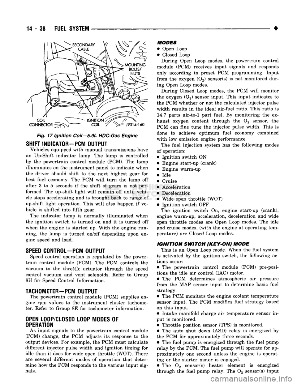
Fig.
17 Ignition Coil—5.9L
HDC-Gas
Engine
SHIFT INDICATOR-PCM
OUTPUT
Vehicles equipped with manual transmissions have
an Up-Shift indicator lamp. The lamp is controlled
by the powertrain control module (PCM). The lamp illuminates on the instrument panel to indicate when
the driver should shift to the next highest gear for
best fuel economy. The PCM will turn the lamp off after 3 to 5 seconds if the shift of gears is not per
formed. The up-shift light will remain off until vehi cle stops accelerating and is brought back to range of
up-shift light operation. This will also happen if ve
hicle is shifted into fifth gear. The indicator lamp is normally illuminated when
the ignition switch is turned on and it is turned off
when the engine is started up. With the engine run
ning, the lamp is turned on/off depending upon en
gine speed and load.
SPEED
CONTROL-PCM
OUTPUT
Speed control operation is regulated by the power-
train control module (PCM). The PCM controls the
vacuum to the throttle actuator through the speed
control vacuum and vent solenoids. Refer to Group
8H for Speed Control Information.
TACHOMETER—PCM
OUTPUT
The powertrain control module (PCM) supplies en
gine rpm values to the instrument cluster tachome ter. Refer to Group 8E for tachometer information.
OPEN
LOOP/CLOSED LOOP MODES
OF
OPERATION
As input signals to the powertrain control module
(PCM) change, the PCM adjusts its response to the
output devices. For example, the PCM must calculate
different injector pulse width and ignition timing for
idle than it does for wide open throttle (WOT). There
are several different modes of operation that deter
mine how the PCM responds to the various input sig
nals.
MODES
• Open Loop
• Closed Loop During Open Loop modes, the powertrain control
module (PCM) receives input signals and responds
only according to preset PCM programming. Input
from the oxygen (02) sensor(s) is not monitored dur
ing Open Loop modes.
During Closed Loop modes, the PCM will monitor
the oxygen (02) sensor input. This input indicates to
the PCM whether or not the calculated injector pulse width results in the ideal air-fuel ratio. This ratio is 14.7 parts air-to-1 part fuel. By monitoring the ex
haust oxygen content through the 02 sensor, the
PCM can fine tune the injector pulse width. This is done to achieve optimum fuel economy combined
with low emission engine performance.
The fuel injection system has the following modes
of operation:
• Ignition switch ON • Engine start-up (crank)
• Engine warm-up
• Idle
• Cruise • Acceleration
• Deceleration
• Wide open throttle (WOT)
• Ignition switch OFF The ignition switch On, engine start-up (crank),
engine warm-up, acceleration, deceleration and wide
open throttle modes are Open Loop modes. The idle and cruise modes, (with the engine at operating tem
perature) are Closed Loop modes.
IGNITION
SWITCH
(KEY-ON)
MODE
This is an Open Loop mode. When the fuel system
is activated by the ignition switch, the following ac
tions occur:
• The powertrain control module (PCM) pre-posi-
tions the idle air control (IAC) motor. • The PCM determines atmospheric air pressure
from the MAP sensor input to determine basic fuel strategy.
• The PCM monitors the engine coolant temperature sensor input. The PCM modifies fuel strategy based
on this input.
• Intake manifold charge air temperature sensor in
put is monitored.
• Throttle position sensor (TPS) is monitored. • The auto shut down (ASD) relay is energized by
the PCM for approximately three seconds. • The fuel pump is energized through the fuel pump
relay by the PCM. The fuel pump will operate for ap
proximately one second unless the engine is operat ing or the starter motor is engaged.
• The 02 sensor(s) heater element is energized
through the fuel pump relay. The 02 sensor(s) input
Page 900 of 1502
•
FUEL
SYSTEM
14-81
AIR
CONDITIONING
(A/C)
CLUTCH RELAY—PCM
OUTPUT
The PCM activates the A/C compressor through the
A/C clutch relay. The PCM regulates A/C compressor
operation by switching the ground circuit for the A/C
clutch relay on and off. The relay is located in the engine compartment (Fig. 3). By switching the ground path for the relay on and
off, the PCM is able to cycle the A/C compressor
clutch. This is based on changes in engine operating
conditions. If, during A/C operation, the PCM senses
a low idle speed, it will de-energize the relay. This
prevents A/C clutch engagement. The relay will re main de-energized until the idle speed increases.
GENERATOR
FIELD-PCM
OUTPUT
The PCM regulates the charging system voltage
within a range of 12.9 to 15.0 volts. It will control
ASD relay operation. The input (through the PCM)
for the ASD relay comes from the engine speed sen sor. When engine running speed is above 384 rpm, a
signal is sent from the PCM to engage the ASD re
lay. This supplies the necessary generator field wind
ing control. When rpm drops below 320, the signal to
the ASD relay is stopped. Refer to Group 8A, for charging system information.
AIR INTAKE HEATER RELAYS-PCM
OUTPUT
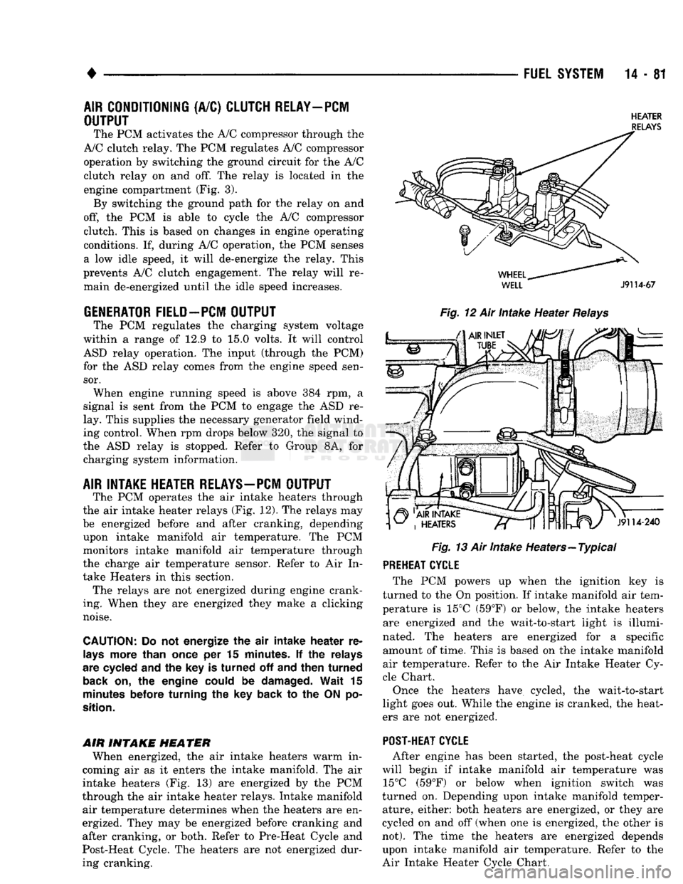
The PCM operates the air intake heaters through
the air intake heater relays (Fig. 12). The relays may
be energized before and after cranking, depending upon intake manifold air temperature. The PCM
monitors intake manifold air temperature through
the charge air temperature sensor. Refer to Air In
take Heaters in this section. The relays are not energized during engine crank
ing. When they are energized they make a clicking
noise.
CAUTION:
Do not energize the air intake heater re
lays
more than
once
per 15
minutes.
If the relays
are
cycled
and the key is turned off and then turned
back
on, the engine
could
be
damaged.
Wait 15
minutes
before
turning the key back to the ON po
sition.
AIR INTAKE
HEATER
When energized, the air intake heaters warm in
coming air as it enters the intake manifold. The air
intake heaters (Fig. 13) are energized by the PCM
through the air intake heater relays. Intake manifold air temperature determines when the heaters are en
ergized. They may be energized before cranking and
after cranking, or both. Refer to Pre-Heat Cycle and
Post-Heat Cycle. The heaters are not energized dur ing cranking.
HEATER
RELAYS
WELL
J9114-67
Fig.
12 Air Intake Heater
Relays
Fig.
13 Air Intake Heaters—Typical PREHEAT CYCLE
The PCM powers up when the ignition key is
turned to the On position. If intake manifold air tem
perature is 15°C (59°F) or below, the intake heaters are energized and the wait-to-start light is illumi
nated. The heaters are energized for a specific amount of time. This is based on the intake manifold
air temperature. Refer to the Air Intake Heater Cy
cle Chart.
Once the heaters have cycled, the wait-to-start
light goes out. While the engine is cranked, the heat
ers are not energized.
POST-HEAT CYCLE
After engine has been started, the post-heat cycle
will begin if intake manifold air temperature was 15°C (59°F) or below when ignition switch was
turned on. Depending upon intake manifold temper ature, either: both heaters are energized, or they are
cycled on and off (when one is energized, the other is
not).
The time the heaters are energized depends upon intake manifold air temperature. Refer to the
Air Intake Heater Cycle Chart.
Page 949 of 1502
16-4 PROPELLER SHAFTS
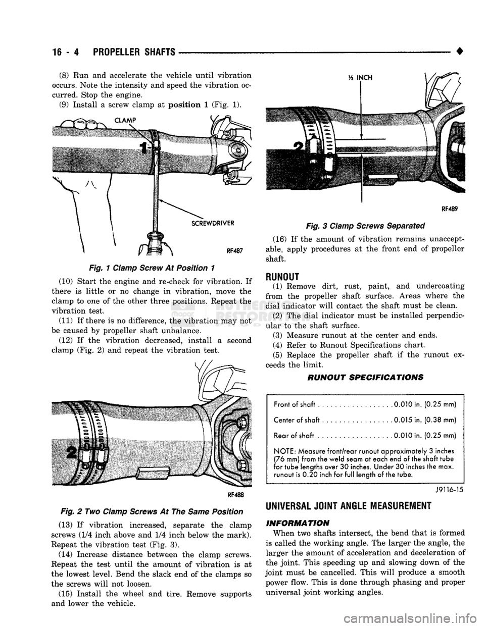
• (8) Run and accelerate the vehicle until vibration
occurs. Note the intensity and speed the vibration oc
curred. Stop the engine. (9) Install a screw clamp at position I (Fig. 1).
Fig.
1 Clamp
Screw
At Position 1
(10) Start the engine and re-check for vibration. If
there is little or no change in vibration, move the clamp to one of the other three positions. Repeat the
vibration test.
(11) If there is no difference, the vibration may not
be caused by propeller shaft unbalance. (12) If the vibration decreased, install a second
clamp (Fig. 2) and repeat the vibration test.
Fig.
2 Two
Clamp
Screws
At The
Same
Position
(13) If vibration increased, separate the clamp
screws (1/4 inch above and 1/4 inch below the mark).
Repeat the vibration test (Fig. 3).
(14) Increase distance between the clamp screws.
Repeat the test until the amount of vibration is at
the lowest level. Bend the slack end of the clamps so the screws will not loosen.
(15) Install the wheel and tire. Remove supports
and lower the vehicle.
RF4B9
Fig.
3
Clamp
Screws
Separated (16) If the amount of vibration remains unaccept
able,
apply procedures at the front end of propeller
shaft.
RUNOUT (1) Remove dirt, rust, paint, and undercoating
from the propeller shaft surface. Areas where the dial indicator will contact the shaft must be clean. (2) The dial indicator must be installed perpendic
ular to the shaft surface. (3) Measure runout at the center and ends. (4) Refer to Runout Specifications chart.
(5) Replace the propeller shaft if the runout ex
ceeds the limit.
RUNOUT
SPECIFICATIONS
Front of shaft 0.010 in. (0.25 mm)
Center of shaft . 0.015 in. (0.38 mm) Rear of
shaft
.
0.010
in. (0.25 mm)
NOTE: Measure front/rear runout approximately 3 inches
(76 mm) from the weld seam at each end of the
shaft
tube
for tube lengths over 30 inches. Under 30 inches the max. runout is 0.20 inch for full length of
the
tube.
J9116-15
UNIVERSAL JOINT
ANGLE
MEASUREMENT
INFORMATION
When two shafts intersect, the bend that is formed
is called the working angle. The larger the angle, the
larger the amount of acceleration and deceleration of
the joint. This speeding up and slowing down of the
joint must be cancelled. This will produce a smooth power flow. This is done through phasing and proper universal joint working angles.
Page 963 of 1502
19
- 2
STEERING
• Dodge
Ram
Truck power steering pumps
are
not interchangeable with
pumps installed
in
other vehicles.
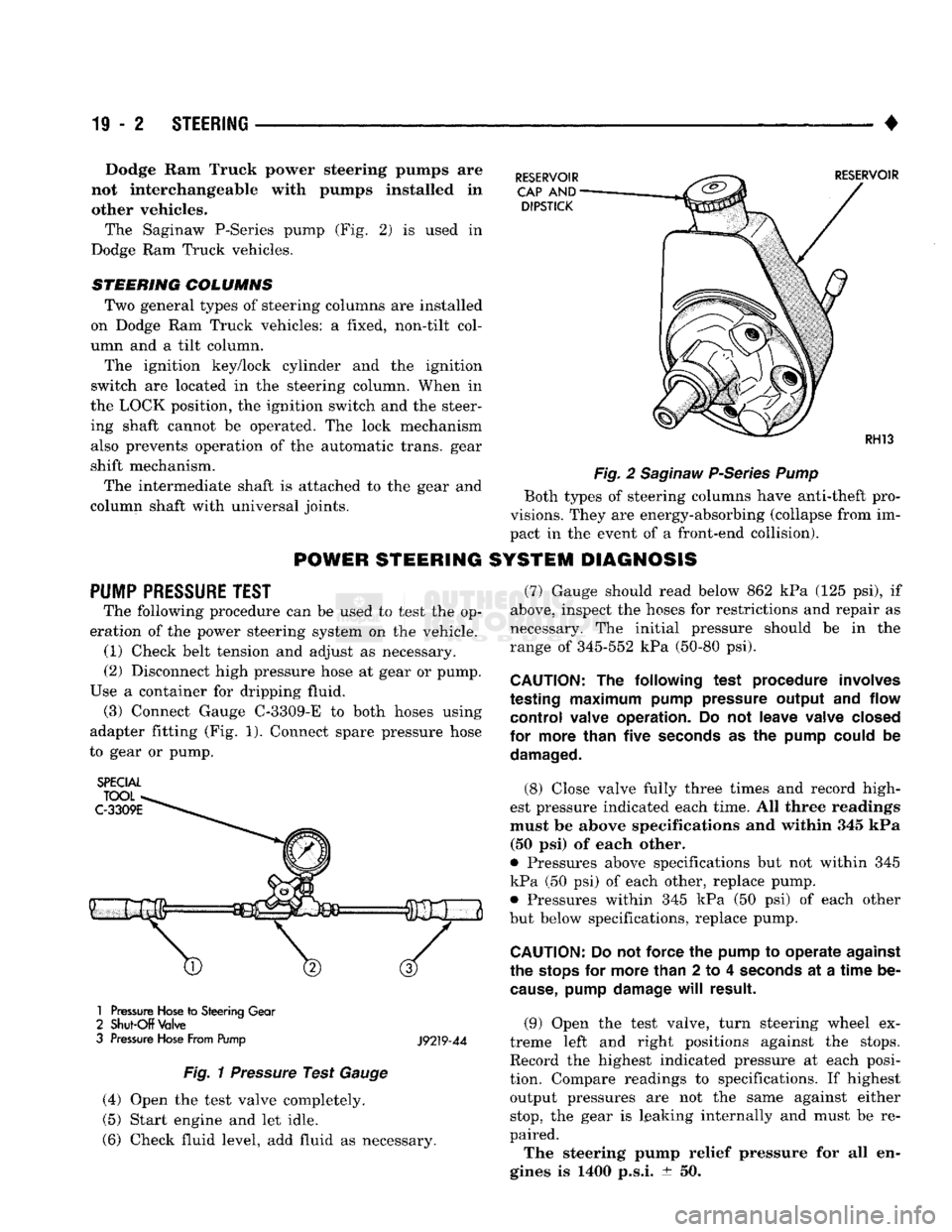
The Saginaw P-Series pump
(Fig. 2) is
used
in
Dodge
Ram
Truck vehicles.
STEERING COLUMNS
Two general types
of
steering columns
are
installed
on Dodge
Ram
Truck vehicles:
a
fixed, non-tilt col
umn
and a
tilt column.
The ignition key/lock cylinder
and the
ignition
switch
are
located
in the
steering column. When
in
the LOCK position,
the
ignition switch
and the
steer ing shaft cannot
be
operated.
The
lock mechanism also prevents operation
of the
automatic trans, gear
shift mechanism.
The intermediate shaft
is
attached
to the
gear
and
column shaft with universal joints.
POWER
STEERING
PUMP
PRESSURE
TEST
The following procedure
can be
used
to
test
the op
eration
of the
power steering system
on the
vehicle. (1) Check belt tension
and
adjust
as
necessary.
(2) Disconnect high pressure hose
at
gear
or
pump.
Use
a
container
for
dripping fluid. (3) Connect Gauge C-3309-E
to
both hoses using
adapter fitting
(Fig. 1).
Connect spare pressure hose
to gear
or
pump.
SPECIAL
1
Pressure
Hose
to
Steering
Gear
2
Shut-Off
Valve
3
Pressure
Hose
From Pump
J9219-44
Fig.
1
Pressure
Test
Gauge
(4) Open
the
test valve completely.
(5) Start engine
and let
idle.
(6) Check fluid level,
add
fluid
as
necessary.
Fig.
2
Saginaw
P-Series
Pump
Both types
of
steering columns have anti-theft pro
visions. They
are
energy-absorbing (collapse from
im
pact
in the
event
of a
front-end collision).
SYSTEM DIAGNOSIS
(7) Gauge should read below
862 kPa (125 psi), if
above, inspect
the
hoses
for
restrictions
and
repair
as
necessary.
The
initial pressure should
be in the
range
of
345-552
kPa
(50-80
psi).
CAUTION:
The
following test procedure involves
testing
maximum
pump pressure output
and
flow control valve operation.
Do not
leave valve closed
for more than five
seconds
as the
pump could
be
damaged.
(8) Close valve fully three times
and
record high
est pressure indicated each time.
All
three readings
must
be
above specifications
and
within
345 kPa
(50
psi) of
each other.
9
Pressures above specifications
but not
within
345
kPa
(50 psi) of
each other, replace pump. • Pressures within
345 kPa (50 psi) of
each other
but below specifications, replace pump.
CAUTION:
Do not
force
the
pump
to
operate against
the
stops
for
more than
2 to 4
seconds
at a
time
be
cause,
pump damage
will
result.
(9) Open
the
test valve, turn steering wheel
ex
treme left
and
right positions against
the
stops.
Record
the
highest indicated pressure
at
each posi
tion. Compare readings
to
specifications.
If
highest output pressures
are not the
same against either
stop,
the
gear
is
leaking internally
and
must
be re
paired.
The steering pump relief pressure
for all en
gines
is 1400
p.s.i.
± 50.
Page 977 of 1502
19
- 16
STEERING
•
EXPANSION PLUG
-
DO NOT
REMOVE; IF DEFORMED
OR
DISLODGED,
REPLACE
HOUSING
RESERVOIR
HOUSING
CAP
SEAL FITTING
75 N-m
(55
FT.
LBS.)
9119-9
(5)
Start the engine. Slowly turn
wheel right and left, lightly contacting the wheel
stops.
(6) Add power steering fluid if necessary.
(7) Lower the vehicle and turn the steering wheel
slowly from lock to lock. (8) Stop the engine. Check the fluid level and refill
as required. (9) If the fluid is extremely foamy, allow the vehi
cle to stand a few minutes and repeat the above pro cedure.
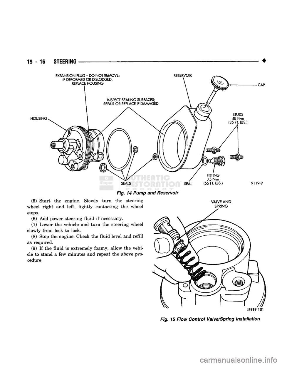
Fig.
14
Pump
and Reservoir
the steering
VALVE
AND
SPRING
J8919-101
Fig.
15 Flow Control Valve/Spring
Installation
Page 981 of 1502
19-20
STEERING
•
RECIRCULATING BALL POWER STEERING GEAR
INDEX
page
Adjuster
Plug Assembly Replacement
26
Check
Valve Replacement
32
Gear
Disassembly
Information
23
Housing
End
Plug
25
Pitman Shaft
and
Side Cover Replacement
25
Pitman Shaft
Seals
— in
Car
Replacement
..... 20
page
Pitman Shaft
Seals
and
Bearing Replacement
. . . 31
Rack
Piston
and
Worm Shaft Replacement
..... 29
Service
Information
20
Steering Gear Adjustments
22
Steering Gear Replacement
32
Valve
Replacement
27
SERVICE
INFORMATION
A recirculating-ball steering gear
is
used with
the
power (assisted) steering system.
The
power steering gear
can be
adjusted
and
internally serviced.
PITMAN
SHAFT
SEALS
- IN
CAR
REPLACEMENT
REMOVAL (1)
Remove pitman
arm
from gear. Refer
to
Pit
man
Arm
Removal
in
Steering Linkage.
(2)
Clean exposed
end of
pitman shaft
and
housing.
Use
a
wire brush
to
clean
the
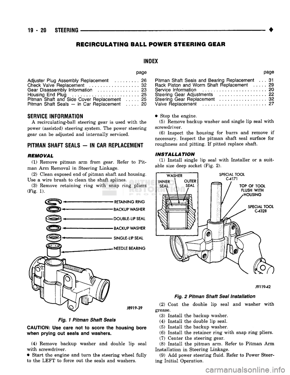
shaft splines. (3) Remove retaining ring with snap ring pliers
(Fig.
1).
RETAINING RING
BACKUP
WASHER
DOUBLE-UP SEAL
BACKUP
WASHER
SINGLE-LIP
SEAL
NEEDLE
BEARING
J8919-39
Fig.
1
Pitman Shaft
Seals
CAUTION:
Use
care
not to
score
the
housing bore
when prying
out
seals
and
washers.
(4) Remove backup washer
and
double
lip
seal
with screwdriver.
• Start
the
engine
and
turn
the
steering wheel fully
to
the
LEFT
to
force
out the
seals
and
washers. • Stop
the
engine.
(5)
Remove backup washer
and
single
lip
seal with
screwdriver.
(6)
Inspect
the
housing
for
burrs
and
remove
if
necessary. Inspect
the
pitman shaft seal surface
for
roughness
and
pitting.
If
pitted replace shaft.
INSTALLATION
(1)
Install single
lip
seal with Installer
or a
suit
able size deep socket
(Fig. 2).
SPECIAL
TOOL
C4171
TOP
OF
TOOL
FLUSH
WITH
HOUSING
SPECIAL
TOOL
G4328
J9119-42
Fig.
2
Pitman Shaft
Seal
Installation
(2)
Coat
the
double
lip
seal
and
washer with
grease.
(3) Install
the
backup washer.
(4) Install
the
double
lip
seal.
(5)
Install
the
backup washer.
(6)
Install
the
retainer ring with snap ring pliers. (7) Center
the
steering gear.
(8) Install
the
pitman
arm.
Refer
to
Pitman
Arm
Installation
in
Steering Linkage. (9)
Add
power steering fluid. Refer
to
Power Steer
ing Initial Operation.