1993 DODGE TRUCK fuel filter
[x] Cancel search: fuel filterPage 721 of 1502
9
- 116 5.9L
(DIESEL) ENGINE
•
CYLINDER HEAD
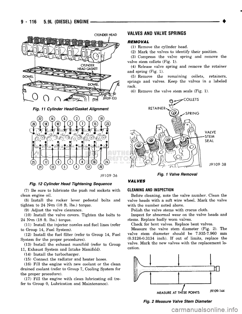
Fig. 11 Cylinder Head/Gasket Alignment J9109-36
Fig. 12 Cylinder Head Tightening Sequence
(7) Be sure to lubricate the push rod sockets with
clean engine oil.
(8) Install the rocker lever pedestal bolts and
tighten to 24 N*m (18 ft. lbs.) torque. (9) Adjust the valve clearance.
(10) Install the valve covers. Tighten the bolts to
24 N*m (18 ft. lbs.) torque.
(11) Install the injector nozzles and fuel lines (refer
to Group 14, Fuel System).
(12) Install the fuel filter (refer to Group 14, Fuel
System for the proper procedures). (13) Install the exhaust manifold (refer to Group
11,
Exhaust System and Intake Manifold).
(14) Install the turbocharger.
(15) Connect the radiator and heater hoses. (16) Fill the engine with new coolant or the clean
drained coolant (refer to Group 7, Cooling System for
the proper procedure). (17) Fill the engine with clean lubricating oil (re
fer to Group 0, Lubrication and Maintenance).
VALVES
AND VALVE
SPRINGS
REMOWAL
(1) Remove the cylinder head.
(2) Mark the valves to identify their position.
(3) Compress the valve spring and remove the
valve stem collets (Fig. 1). (4) Release valve spring and remove the retainer
and spring (Fig. 1).
(5) Remove the remaining collets, retainers,
springs and valves. Keep the valves in a labeled
rack.
(6) Remove the valve stem seals (Fig. 1). -38
Fig. 1 Valve Removal
WALVES
CLEANING AND INSPECTION
Before cleaning, note the valve number. Clean the
valve heads with a soft wire wheel. Mark the valve
with the numbet* noted above.
Polish the valve stems with crocus cloth.
Inspect for abnormal wear on the valve heads and
stems.
Replace badly worn valves. Check for bent valves. Replace bent valves.
Measure the valve stem diameter (Fig. 2). The
valve stem diameter should be 7.935-7.960 mm (0.3126-0.3134 inch). If out of limits, replace the
valve. Mark the new valves with the replacement lo cation. Ik 1
MEASURE
AT THESE POINTS
Fig. 2 Measure Valve Stem Diameter
Page 751 of 1502
9
- 148 5.9L
(DIESEL) ENGINE
• Make sure the idler gear pin is installed in the lo
cating bore in the cylinder block. (2) Install the pump. Tighten the oil pump mount
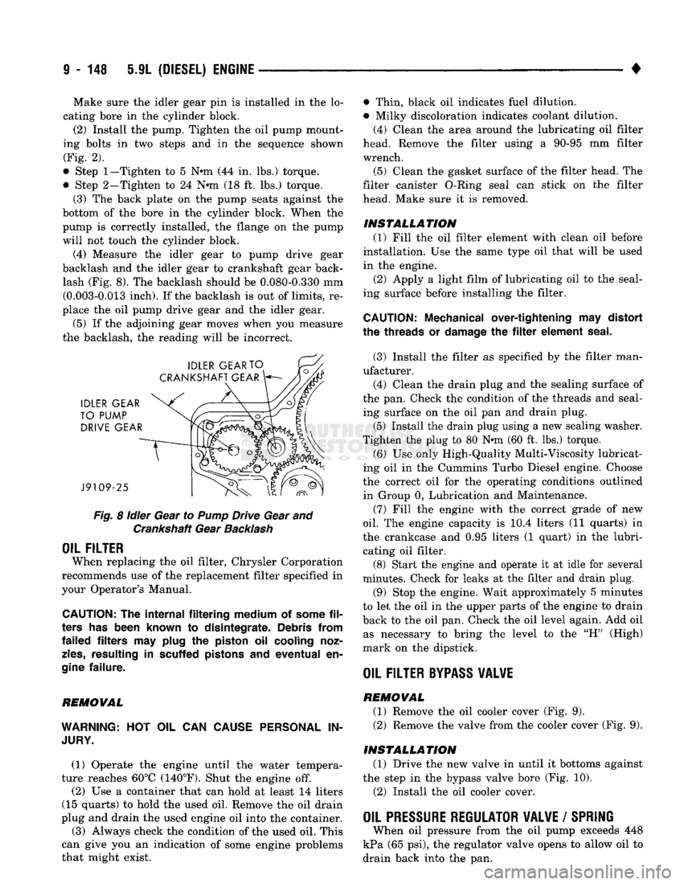
ing bolts in two steps and in the sequence shown (Fig. 2).
• Step
1—Tighten
to 5 N«m (44 in. lbs.) torque.
• Step 2-Tighten to 24 N*m (18 ft. lbs.) torque. (3) The back plate on the pump seats against the
bottom of the bore in the cylinder block. When the
pump is correctly installed, the flange on the pump will not touch the cylinder block.
(4) Measure the idler gear to pump drive gear
backlash and the idler gear to crankshaft gear back lash (Fig. 8). The backlash should be 0.080-0.330 mm (0.003-0.013 inch). If the backlash is out of limits, re
place the oil pump drive gear and the idler gear.
(5) If the adjoining gear moves when you measure
the backlash, the reading will be incorrect.
Fig.
8
idler
Gear to
Pump
Drive Gear and Crankshaft Gear
Backlash
OIL FILTER
When replacing the oil filter, Chrysler Corporation
recommends use of the replacement filter specified in
your Operator's Manual.
CAUTION:
The
internal filtering medium
of
some
fil
ters
has
been known
to
disintegrate. Debris from
failed filters
may
plug
the
piston
oil
cooling noz
zles,
resulting
in
scuffed pistons
and
eventual
en
gine
failure.
REMOVAL
WARNING:
HOT OIL CAN
CAUSE PERSONAL
IN
JURY.
(1) Operate the engine until the water tempera
ture reaches 60°C (140°F). Shut the engine off.
(2) Use a container that can hold at least 14 liters
(15 quarts) to hold the used oil. Remove the oil drain
plug and drain the used engine oil into the container.
(3) Always check the condition of the used oil. This
can give you an indication of some engine problems
that might exist. • Thin, black oil indicates fuel dilution.
• Milky discoloration indicates coolant dilution.
(4) Clean the area around the lubricating oil filter
head. Remove the filter using a 90-95 mm filter
wrench.
(5) Clean the gasket surface of the filter head. The
filter canister O-Ring seal can stick on the filter
head. Make sure it is removed.
INSTALLATION (1) Fill the oil filter element with clean oil before
installation. Use the same type oil that will be used
in the engine.
(2) Apply a light film of lubricating oil to the seal
ing surface before installing the filter.
CAUTION:
Mechanical over-tightening
may
distort
the threads
or
damage
the filter
element seal.
(3) Install the filter as specified by the filter man
ufacturer. (4) Clean the drain plug and the sealing surface of
the pan. Check the condition of the threads and seal ing surface on the oil pan and drain plug.
(5) Install the drain plug using a new sealing washer.
Tighten the plug to 80 N-m (60 ft. lbs.) torque.
(6) Use only High-Quality Multi-Viscosity lubricat
ing oil in the Cummins Turbo Diesel engine. Choose
the correct oil for the operating conditions outlined in Group 0, Lubrication and Maintenance.
(7) Fill the enginfe with the correct grade of new
oil.
The engine capacity is i0.4 liters (11 quarts) in
the crankcase and 0.95 liters (1 quart) in the lubri cating oil filter. (8) Start the engine and operate it at idle for several
minutes. Check for leaks at the filter and drain plug.
(9) Stop the engine. Wait approximately 5 minutes
to let the oil in the upper parts of the engine to drain
back to the oil pan. Check the oil level again. Add oil as necessary to bring the level to the "H" (High)
mark on the dipstick.
OIL FILTER
BYPASS
VALWE
REMOVAL
(1) Remove the oil cooler cover (Fig. 9). (2) Remove the valve from the cooler cover (Fig. 9).
INSTALLATION (1) Drive the new valve in until it bottoms against
the step in the bypass valve bore (Fig. 10).
(2) Install the oil cooler cover.
OIL PRESSURE REGULATOR VALVE
/
SPRING
When oil pressure from the oil pump exceeds 448
kPa (65 psi), the regulator valve opens to allow oil to
drain back into the pan.
Page 756 of 1502
5.9L
(DIESEL)
ENGINE
9-153
TORQUE
SPECIFICATIONS
COMPONENT
Air
Fuel
Control
Banjo Screw (In Pump) ....
Air
Fuel
Control
Fitting
(In
Head)
Alternator
Ground Cable Mounting to
Block
Alternator
Mounting to
Water
Pump
Inlet
..
Alternator
Pulley
Alternator
Support
(Upper)
Battery
Cable
(Negative)
Mounting to Block ,
Belt
Tensioner
Mounting
Block
Heater
Mounting
Cab
Heater
Hose
Clamp
Cab
Heater
Tubing
Clamp Mounting.......
Camshaft
Thrust
Plate
Clutch Cover Mounting to
Flywheel
...
Connecting Rod
(Alternately
tighten
in 3 steps) Step 1
Step 2
Step 3 .
Cooling Fan Mounting to
Fan
Clutch
Crossover
Clamp (Air)
Cylinder
Head
Mounting Bolts
1.
All
Bolts....
2.
Long
Bolts
.........
3.
Tighten
All
Bolts
An
Additional
Exhaust
Manifold
Exhaust
Outlet
Pipe
- V
Band
Clamp
Exhaust
Pipe
Clamp Mounting
Exhaust
Pipe
Steady
Rest
Mounting to Trans .
Fan
Clutch Mounting/Fan Hub
(L
Hand
Threads)..
Fan Hub
Bracket
Mounting
Fan Hub Bearing
Retaining
Capscrew
Fan
Pulley
to
Fan
Hub
Fan
Pulley
Crankshaft .
Fan
Shroud
Mounting Nuts
Flywheel
Bolts
Flywheel
Housing
- Adaptor
Front
Engine
Mount Isolator Mounting to Mount..
Front
Engine
Mount Through Bolt
Front
Engine
Mount to Block
Front
Oil
Filler
Pipe
-
Access
Cover
Fuel
Banjo Screw (In
Fuel
Pump)
Fuel
Banjo Screw (In
Head)
Fuel
Banjo Screw (In
Injector)
Fuel
Filter
Fuel
Heater
Assembly
Mounting
Fuel
Heater
Ground Mounting to
Intake
Manifold
Fuel
Link
Fitting
(High Pressure)
Fuel
Low Pressure Supply
Fuel
Pump
Drive
Gear
(With
Pump
Unlocked)
Fuel
Pump Lock (Bosch)
TORQUE
12 N-m 9 ft. lbs.
8 N-m 6 ft. lbs.
24 N-m 18 ft. lbs.
41 N*m 30 ft. lbs.
80 N-m 60 ft. lbs.
24 N-m 18 ft. lbs.
77 N-m 57 ft. lbs.
43 N-m 32 ft. lbs.
12 N-m 9 ft. lbs.
4 N-m (35 in. lbs.)
24 N-m 18 ft. lbs.
24 N-m 18 ft. lbs.
23 N-m 17 ft. lbs.
35 N-m 26 ft. lbs.
70 N-m 51 ft. lbs.
100 N-m 73 ft. lbs.
20 N-m 15 ft. lbs.
5
N-m (44 in. lbs.)
90 N-m 66 ft. lbs.
120 N-m 89 ft. lbs.
90°
43 N-m 32 ft. lbs.
8 N-m (72 in. lbs.)
27 N-m 20 ft. lbs.
68 N-m 50 ft. lbs.
57 N-m 42 ft. lbs.
24 N-m 18 ft. lbs.
77 N-m 57 ft. lbs.
9 N-m 7 ft. lbs.
9 N-m 7 ft. lbs.
11 N-m (95 in. lbs.)
137 N-m 101 ft. lbs.
60 N-m 44 ft. lbs.
109 N-m 80 ft. lbs.
41 N-m 30 ft. lbs.
60 N-m 44 ft. lbs.
Hand
Tighten
32 N-m 24 ft. lbs.
24 N-m 18 ft. lbs.
8 N-m 6 ft. lbs.
Vi
Turn
after
contact
32 N-m 24 ft. lbs.
12 N-m 9 ft. lbs.
24 N-m 18 ft. lbs.
24 N-m 18 ft. lbs.
65 N-m 48 ft. lbs.
30 N-m 22 ft. lbs.
J9109-261
Page 757 of 1502
9
- 154 5.9L
(DIESEL)
ENGINE
TORQUE
SPECIFICATIONS
(CONT.J
COMPONENT
TORQUE
Fuel
Pump
Mounting
Nut
..
Fuel
Pump
Solenoid
Fuel
Pump
Support
Bracket
Fuel
Pump
Unlock
(Bosch)
.
Fuel
Vent
Screw
(In Banjo)
.
Gear
Cover
Gear
Housing-to-Block
Injector
Retaining Nut.
Intake
Manifold
Cover
Intercooler
Attaching
Bolts
•
•
Intercooler
Duct
Clamp
Nuts.
Lift
Pump
Mounting
Lifting Bracket (Rear)
..
Main
Bearing
Cap
Bolts.
Step!.
Step
2.
Steo3.
Oil
Cooler
Assembly
Oil
Fill
Tube Bracket
Oil
Filter
Oil
Pan
Drain
Plug
Oil
Pan
Mounting.........
Oil
Pressure
Regulator
Plug
Oil
Pressure
Sender/Switch
Oil
Pump
Mounting
Oil
Suction
Tube (Flange)
..
Oil
Suction
Tube
Brace
Power Steering
Pump
to
Vacuum
Pump
Mounting
Radiator Hose Clamp
-
Upper
Radiator Mounting Nuts Rear Seal Mounting
Refrigerant
Compressor
Lines
-
Flange Mounting
Refrigerant
Compressor
Mounting
Rocker Lever Nut
Rocker Support
Starter
Mounting
Starter
Battery
(Positive) Cable Nut
Starter
Solenoid Nut
Tappet
Cover/Fuel Drain Line Supports
Thermistor
,
Thermostat Housing
Throttle
Bracket Mounting to Mounting Bracket.
Throttle
Rod
Mounting to
Throttle
Lever Nut
...
Timing Pin Flange Mounting
Torque Converter
Access
Cover
Plate
Mounting
Transfer
Case
Linkage Bracket Mounting/Trans Transfer
Case
Mounting to
Transmission
..
24
N-m
18
ft.
lbs.
43
N-m
32 ft. lbs.
24
N-m
18
ft.
lbs.
13
N-m
10
ft. lbs.
8
N-m
6 ft. lbs.
24
N-m
18
ft.
lbs.
24
N-m
18
ft.
lbs.
60
N-m
44
ft.
lbs.
24
N-m
18
ft.
lbs.
2
N-m
(17
in.
lbs.)
8
N-m
(72
in.
lbs.)
24
N-m
18
ft.
lbs.
77
N-m
57
ft.
lbs.
60 N-m 45 ft. lbs.
119
N-m
88
ft.
lbs.
176 N-m 129
ft.
lbs.
24
N-m
18
ft.
lbs.
43
N-m
32
ft.
lbs.
Turn
after
contact
80 N-m 60 ft. lbs.
24
N-m
18
ft.
lbs.
80 N-m 60 ft. lbs.
16
N-m
12 ft. lbs.
24
N-m
18
ft.
lbs.
24
N-m
18
ft.
lbs.
24
N-m
18
ft.
lbs.
24
N-m
18
ft.
lbs.
4
N-m
(35 in. lbs.)
11
N-m
(95 in. lbs.)
9 N-m 7
ft.
lbs.
20
N-m
15
ft.
lbs.
47
N-m
35 ft. lbs.
24
N-m
18
ft.
lbs.
24
N-m
18
ft.
lbs.
43
N-m
32
ft.
lbs.
22
N-m
16
ft. lbs.
5
N-m
(44 in. lbs.)
24
N-m
18
ft.
lbs.
24
N-m
18
ft.
lbs.
24
N-m
18
ft.
lbs.
24
N-m
18
ft.
lbs.
10 N-m
73
ft.
lbs.
5
N-m
(44 in. lbs.)
4
N-m
(35
in. lbs.)
41
N-m
30 ft. lbs.
47
N-m
35 ft. lbs.
J9109-262
Page 820 of 1502
•
FUEL
SYSTEM
14 - 1
FUEL
SYSTEM
page
ACCELERATOR
PEDAL
AND THROTTLE
CABLE
................ 25
DIESEL
FUEL
INJECTION-COMPONENT
DESCRIPTION/SYSTEM
OPERATION
76
DIESEL
FUEL
INJECTION-GENERAL
DIAGNOSIS
88
DIESEL
FUEL
INJECTION-SERVICE
PROCEDURES
....................... 106
FUEL
DELIVERY
SYSTEM-EXCEPT
DIESEL
.. 3
FUEL
DELIVERY-DIESEL
ENGINE
15
FUEL
TANKS
.... 20
page
GENERAL
INFORMATION 1
MULTI-PORT
FUEL
INJECTION (MPI)-
COMPONENT
DESCRIPTION/SYSTEM
OPERATION-EXCEPT
DIESEL
29
MULTI-PORT
FUEL
INJECTION (MPI)-
COMPONENT
REMOVAL/INSTALLATION-
EXCEPT
DIESEL
64
MULTI-PORT
FUEL
INJECTION (MPI)-
GENERAL
DIAGNOSIS-EXCEPT
DIESEL
...43
SERVICE
ADJUSTMENTS-DIESEL
122
SPECIFICATIONS
123
GENERAL INFORMATION
Throughout this group, references are made to par
ticular vehicle models by alphabetical designation or
by the particular vehicle nameplate. A chart showing a breakdown of the alphabetical designations is in
cluded in the Introduction section at the beginning of
this manual.
The 5.9L (V-8) gas powered engine will be referred
to in this group as either the: LDC (Light Duty Cy cle) or HDC (Heavy Duty Cycle) engine. The HDC engine can be easily identified by the use of an en
gine mounted air injection pump. The 3.9L/5.2L/5.9L
LDC engine will not use an air injection pump.
This Fuel System group will cover all fuel system
components for the 3.9L (V-6), 5.2L (V-8), 5.9L LDC
(V-8),
5.9L HDC (V-8) and 5.9L (in-line six cylinder)
diesel engines.
The Fuel System consists of: the fuel tank, an
electric (fuel tank mounted) fuel pump and fuel fil
ter. It also consists of fuel tubes/lines/hoses, vacuum
hoses,
throttle body and fuel injector(s).
The Fuel Delivery System consists of: the electric
fuel pump, fuel filter, fuel tubes/lines/hoses, fuel rail,
fuel injectors and fuel pressure regulator.
A Fuel Return System is used on all vehicles (all
engines) except the 5.9L (V-8) gas powered engine. On this engine, a returnless type fuel system is
used. The fuel return system consists of fuel tubes/
lines and hoses that route fuel back to the fuel tank.
The Fuel Tank Assembly consists of: the fuel
tank, filler tube, fuel gauge sending unit/electric fuel
pump module, a pressure relief/rollover valve and a
pressure-vacuum filler cap. Also to be considered part of the fuel system is the
Evaporation Control System. This is designed to
reduce the emission of fuel vapors into the atmo sphere. The description and function of the Evapora
tive Control System is found in Group 25, Emission Control Systems.
FUEL
USAGE
STATEMENT-GAS
ENGINES
Your vehicle was designed to meet all emission
regulations and provide excellent fuel economy using
high quality unleaded gasoline. Only use unleaded gasolines having a minimum posted octane of 87. If your vehicle develops occasional light spark
knock (ping) at low engine speeds, this is not harm
ful.
However, continued heavy knock at high speeds can cause damage and should be re
ported to your dealer immediately. Engine dam age as a result of heavy knock operation may not be
covered by the new vehicle warranty. In addition to using unleaded gasoline with the
proper octane rating, those that contain deter
gents,
corrosion and stability additives are rec
ommended. Using gasolines that have these additives will help improve fuel economy, reduce
emissions and maintain vehicle performance. Gener ally, premium unleaded gasolines contain more addi
tive than regular unleaded gasolines. Poor quality gasoline can cause problems such as
hard starting, stalling and stumble. If you experience
these problems, use another brand of gasoline before considering service for the vehicle.
Page 821 of 1502
14
- 2
FUEL SYSTEM
•
GASOLINE/OXYGENATE
BLENDS
Some fuel suppliers blend unleaded gasoline with
materials that contain oxygen such as alcohol, MTBE and ETBE. The type and amount of oxygenate used
in the blend is important. The following are gener
ally used in gasoline blends:
ETHANOL
Ethanol (Ethyl or Grain Alcohol) properly blended,
is used as a mixture of 10 percent ethanol and 90
percent gasoline. Gasoline with ethanol may be
used in your vehicle.
METHANOL
CAUTION:
DO NOT USE
GASOLINES CONTAINING
METHANOL.
Use of methanol/gasoline blends may re
sult in starting and driveability problems. In addition,
damage may be done to critical fuel system compo
nents.
Methanol (Methyl or Wood Alcohol) is used in a va
riety of concentrations blended with unleaded gaso
line.
You may encounter fuels containing 3 percent
or more methanol along with other alcohols called co-
solvents.
Problems that are the result of using methanol/gas
oline blends are not the responsibility of Chrysler Corporation. They may not be covered by the vehicle
warranty.
MTBE/ETBE
Gasoline and MTBE (Methyl Tertiary Butyl Ether)
blends are a mixture of unleaded gasoline and up to 15 percent
MTBE.
Gasoline and
ETBE
(Ethyl
Ter
tiary Butyl Ether) are blends of gasoline and up to 17 percent ETBE. Gasoline blended with MTBE or
ETBE may be used in your vehicle.
CLEAN
AIR GASOLINE Many gasolines are now being blended that con
tribute to cleaner air, especially in those areas of the
country where air pollution levels are high. These
new blends provide a cleaner burning fuel and some are referred to as Reformulated Gasoline.
In areas of the country where carbon monoxide lev
els are high, gasolines are being treated with oxy
genated materials such as MTBE, ETBE and ethanol.
Chrysler Corporation supports these efforts toward
cleaner air and recommends that you use these gas
olines as they become available.
FUEL
REQUIREMENTS-DIESEL ENGINE
Use good quality diesel fuel from a reputable sup
plier in your Chrysler Corporation vehicle. For most
year-round service, number 2 (two) diesel fuel meet ing ASTM specification D-975 will provide good per
formance. If the vehicle is exposed to extreme cold (below -18°C - 0°F), or for any reason is required to
operate at colder than normal conditions for pro longed periods, then dilution of the 2D fuel with 50
percent kerosine or number ID diesel fuel will pro
vide better protection from fuel gelling or wax-plug ging of the fuel filters. Diesel fuel is seldom
completely free of water. To prevent fuel system
trouble, including fuel tube (line) freezing in winter, drain the accumulated water using the drain pro
vided. If you buy good quality fuel and follow the cold weather advice above, fuel conditioners should
not be required in your vehicle.
Page 822 of 1502
•
FUEL SYSTEM
14 • 3
FUEL
DELIVERY SYSTEM-EXCEPT DIESEL
INDEX
page
Fuel Filter—3.9L/5.2L Gas Engine
............
10
Fuel
Filter—5.9L
Gas Engine
11
Fuel Pressure Leak Down Test—3.9L/5.2L Engine
. 8
Fuel Pressure Leak Down Test—5.9L Engine
.... 9
Fuel Pump Capacity
Test—All
Gas
Engines
..... 8
Fuel Pump
Control
........................
5
Fuel Pump Module—3.9L/5.2L Engines
3
GENERAL INFORMATION
Two different types
of
fuel delivery/fuel return sys
tems
are
used.
The
system used with
the
3.9L/5.2L
engine will route excess fuel pressure back
to the
fuel tank through
a
fuel return line.
The
system used
with
the 5.9L
engine will
not
have
a
separate fuel
re
turn line. This system will
be
referred
to as a re-
turnless type.
The
fuel pump module used with
the
5.9L engine will contain
a
combination fuel pressure
regulator
and
fuel filter. Refer
to the
following Fuel
Pump Module
for
additional information
or,
refer
to
the Multi-Port Fuel Injection sections
of
this Fuel System group. A separate frame mounted fuel filter will
not be
used with
any 5.9L gas
powered engine.
FUEL
PUMP
M0DULE-3.9L/5.2L
ENGINES
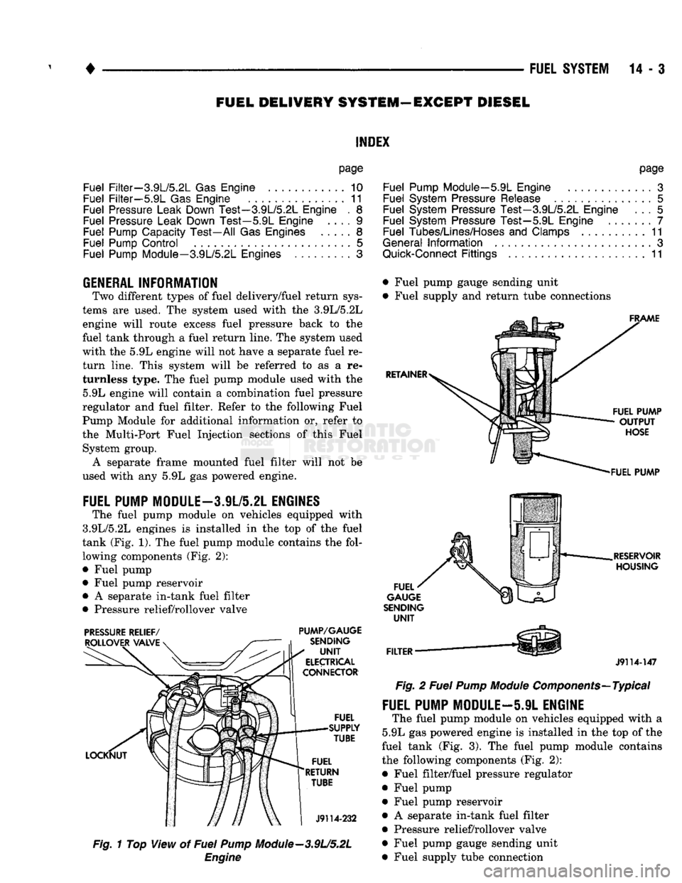
The fuel pump module
on
vehicles equipped with
3.9L/5.2L engines
is
installed
in the top of the
fuel
tank (Fig.
1). The
fuel pump module contains
the
fol lowing components (Fig.
2):
• Fuel pump
• Fuel pump reservoir
•
A
separate in-tank fuel filter
• Pressure relief/rollover valve
PRESSURE
RELIEF/
PUMP/GAUGE
Fig.
1
Top View
of
Fuel
Pump
Module—3.9U5.2L
Engine
page
Fuel Pump Module—5.9L Engine
.............
3
Fuel System Pressure Release
...............
5
Fuel System Pressure Test—3.9L/5.2L Engine
... 5
Fuel System Pressure Test—5.9L Engine
7
Fuel Tubes/Lines/Hoses
and
Clamps
..........
11
General
Information
3
Quick-Connect
Fittings
11
• Fuel pump gauge sending unit
• Fuel supply
and
return tube connections
J9114-147
Fig.
2
Fuel
Pump
Module
Components—Typical
FUEL PUMP MODULE—5.9L ENGINE
The fuel pump module
on
vehicles equipped with
a
5.9L
gas
powered engine
is
installed
in the top of
the
fuel tank
(Fig. 3). The
fuel pump module contains
the following components (Fig.
2):
• Fuel filter/fuel pressure regulator
• Fuel pump • Fuel pump reservoir
•
A
separate in-tank fuel filter
• Pressure relief/rollover valve
• Fuel pump gauge sending unit
• Fuel supply tube connection
Page 823 of 1502
14-4
FUEL
SYSTEM
•
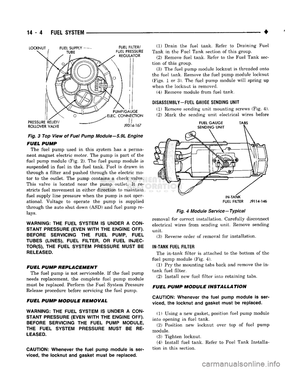
Fig.
3 Top View of
Fuel
Pump
Module—5.9L
Engine
FUEL
PUMP
The fuel pump used in this system has a perma
nent magnet electric motor. The pump is part of the
fuel pump module (Fig. 2). The fuel pump module is suspended in fuel in the fuel tank. Fuel is drawn in
through a filter and pushed through the electric mo
tor to the outlet. The pump contains a check valve.
This valve is located near the pump outlet. It re stricts fuel movement in either direction to maintain
fuel supply line pressure when the pump is not oper ational. Voltage to operate the pump is supplied
through the auto shut down (ASD) and fuel pump re
lays.
WARNING:
THE
FUEL SYSTEM
IS
UNDER
A
CON STANT PRESSURE (EVEN
WITH
THE
ENGINE OFF).
BEFORE
SERVICING
THE
FUEL PUMP, FUEL
TUBES
(LINES), FUEL FILTER,
OR
FUEL
INJEC
TOR^),
THE
FUEL SYSTEM PRESSURE MUST
BE
RELEASED.
FUEL
PUMP
REPLACEMENT
The fuel pump is not serviceable. If the fuel pump
needs replacement, the complete fuel pump module must be replaced. Perform the Fuel System Pressure
Release procedure before servicing the fuel pump.
FUEL
PUMP
MODULE
REMOVAL
WARNING:
THE
FUEL SYSTEM
IS
UNDER
A
CON STANT PRESSURE (EVEN
WITH
THE
ENGINE OFF).
BEFORE
SERVICING
THE
FUEL PUMP MODULE,
THE FUEL SYSTEM PRESSURE MUST
BE RE
LEASED.
CAUTION:
Whenever
the
fuel
pump
module
is
ser
viced,
the
locknut
and gasket
must
be replaced. (1) Drain the fuel tank. Refer to Draining Fuel
Tank in the Fuel Tank section of this group.
(2) Remove fuel tank. Refer to the Fuel Tank sec
tion of this group.
(3) The fuel pump module locknut is threaded onto
the fuel tank. Remove the fuel pump module locknut
(Figs.
1 or 3). The fuel pump module will spring up
when the locknut is removed.
(4)
Remove module from fuel tank.
DISASSEMBLY-
FUEL GAUGE SENDING
UNIT
(1) Remove sending unit mounting screws (Fig. 4).
(2) Mark the sending unit electrical wires before
FUEL
GAUGE
TABS
IN-TANK
FUEL
FILTER
J9114-146
Fig.
4
Module
Service—Typical
removal for correct installation. Carefully disconnect electrical wires from sending unit. Remove sending unit.
(3) Reverse order of removal for installation.
IN-TANK FUEL FILTER
The in-tank filter is attached to the bottom of the
fuel pump module (Fig. 4).
(1) Pry the mounting tabs back and remove the in-
tank fuel filter.
(2) Install new fuel filter into retaining tabs.
FUEL
PUMP
MODULE
INSTALLATION
CAUTION:
Whenever
the
fuel
pump
module
is
ser
viced,
the
locknut
and
gasket must
be
replaced.
(1) Using a new gasket, position fuel pump module
into opening in fuel tank. (2) Position new locknut over top of fuel pump
module. (3) Tighten locknut. (4) Install fuel tank. Refer to Fuel Tank Installa
tion in this section.