1993 DODGE TRUCK fuel filter
[x] Cancel search: fuel filterPage 826 of 1502
•
FUEL
SYSTEM
14 - 7
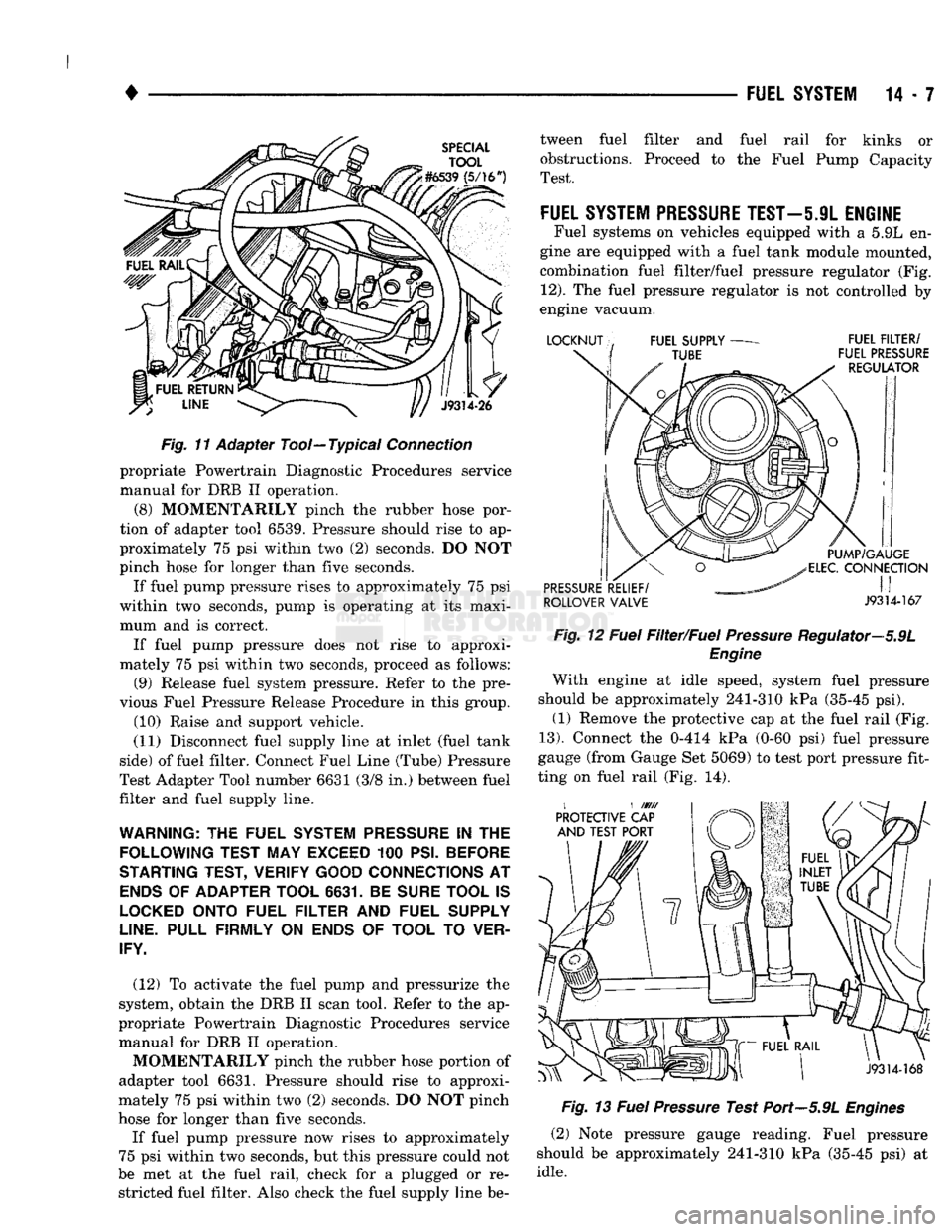
Fig.
1"f
Adapter Tool—Typical
Connection
propriate Powertrain Diagnostic Procedures service
manual for DRB II operation.
(8) MOMENTARILY pinch the rubber hose por
tion of adapter tool 6539. Pressure should rise to ap
proximately 75 psi within two (2) seconds. DO NOT
pinch hose for longer than five seconds.
If fuel pump pressure rises to approximately 75 psi
within two seconds, pump is operating at its maxi mum and is correct. If fuel pump pressure does not rise to approxi
mately 75 psi within two seconds, proceed as follows:
(9) Release fuel system pressure. Refer to the pre
vious Fuel Pressure Release Procedure in this group. (10) Raise and support vehicle.
(11) Disconnect fuel supply line at inlet (fuel tank
side) of fuel filter. Connect Fuel Line (Tube) Pressure
Test Adapter Tool number 6631 (3/8 in.) between fuel
filter and fuel supply line.
WARNING:
THE
FUEL SYSTEM
PRESSURE
IN THE
FOLLOWING TEST MAY EXCEED
100
PSI. BEFORE
STARTING TEST, VERIFY GOOD CONNECTIONS
AT
ENDS
OF
ADAPTER TOOL 6631.
BE
SURE TOOL
IS
LOCKED
ONTO FUEL FILTER
AND
FUEL SUPPLY
LINE.
PULL FIRMLY
ON
ENDS
OF
TOOL
TO
VER
IFY.
(12) To activate the fuel pump and pressurize the
system, obtain the DRB II scan tool. Refer to the ap
propriate Powertrain Diagnostic Procedures service manual for DRB II operation.
MOMENTARILY pinch the rubber hose portion of
adapter tool 6631. Pressure should rise to approxi
mately 75 psi within two (2) seconds. DO NOT pinch
hose for longer than five seconds.
If fuel pump pressure now rises to approximately
75 psi within two seconds, but this pressure could not
be met at the fuel rail, check for a plugged or re stricted fuel filter. Also check the fuel supply line be tween fuel filter and fuel rail for kinks or
obstructions. Proceed to the Fuel Pump Capacity
Test.
FUEL
SYSTEM PRESSURE
TEST—5.9L
ENGINE
Fuel systems on vehicles equipped with a 5.9L en
gine are equipped with a fuel tank module mounted,
combination fuel filter/fuel pressure regulator (Fig.
12).
The fuel pressure regulator is not controlled by
engine vacuum.
ROLLOVER VALVE J9314-167 Fig.
12
Fuel
Filter/Fuel
Pressure
Regulator—5.9L
Engine
With engine at idle speed, system fuel pressure
should be approximately 241-310 kPa (35-45 psi). (1) Remove the protective cap at the fuel rail (Fig.
13).
Connect the 0-414 kPa (0-60 psi) fuel pressure
gauge (from Gauge Set 5069) to test port pressure fit
ting on fuel rail (Fig. 14).
Fig.
13
Fuel
Pressure
Test Port—5.9L
Engines
(2) Note pressure gauge reading. Fuel pressure
should be approximately 241-310 kPa (35-45 psi) at
idle.
Page 827 of 1502
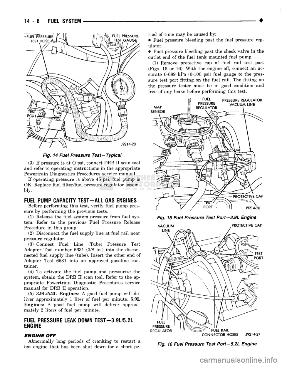
Fig.
14
Fuel
Pressure
Test—Typical
(3) If pressure is at O psi, connect DRB II scan tool
and refer to operating instructions in the appropriate
Powertrain Diagnostics Procedures service manual. If operating pressure is above 45 psi, fuel pump is
OK. Replace fuel filter/fuel pressure regulator assem-
bly.
FUEL
PUMP CAPACITY TEST-ALL GAS ENGINES
Before performing this test, verify fuel pump pres
sure by performing the previous tests. (1) Release the fuel system pressure from fuel sys
tem. Refer to the previous Fuel Pressure Release
Procedure in this group. (2) Disconnect the fuel supply line at fuel rail near
pressure regulator. (3) Connect Fuel Line (Tube) Pressure Test
Adapter Tool number 6631 (3/8 in.) into the discon nected fuel supply line (tube). Insert the other end of
Adapter Tool 6631 into an approved gasoline con
tainer.
(4)
To activate the fuel pump and pressurize the
system, obtain the DRB II scan tool. Refer to the ap
propriate Powertrain Diagnostic Procedures service manual for DRB II operation. (5) 3.9L/5.2L Engines: A good fuel pump will de
liver approximately 1 liter of fuel per minute. 5.9L
Engines: A good fuel pump will deliver approxi
mately 2 liters of fuel per minute.
FUEL
PRESSURE
LEAK DOWN
TEST-3
JL/5.2L
ENGINE
ENGINE
OFF Abnormally long periods of cranking to restart a
hot engine that has been shut down for a short pe riod of time may be caused by:
• Fuel pressure bleeding past the fuel pressure reg
ulator.
• Fuel pressure bleeding past the check valve in the
outlet end of the fuel tank mounted fuel pump. (1) Remove protective cap at fuel rail test port
(Figs.
15 or 16). With the engine off, connect an ac
curate 0-689 kPa (0-100 psi) fuel gauge to the pres
sure test port fitting on the fuel rail. The fitting on
the pressure tester must be in good condition and
free of any leaks before performing this test.
PRESSURE
REGULATOR
CONNECTOR
HOSES
J9214-27
Fig.
16
Fuel
Pressure
Test Port—5.2L
Engine
Page 828 of 1502
•
FUEL
SYSTEM
14 - 9 (2) Start the vehicle and let engine idle. Check
fuel pressure reading on gauge. Fuel pressure should
be within specifications. Refer to the previous Fuel System Pressure Tests.
(3) Shut engine off. Observe and record fuel pres
sure reading on gauge. Leave fuel pressure gauge
connected. Allow engine to set for 30 minutes and
then compare the fuel pressure reading on the gauge
with the reading taken when engine was shut down.
A pressure drop of up to 138 kPa (20 psi) within 30 minutes is within specifications.
(4) If the fuel pressure drop is within specifica
tions,
the fuel pump outlet check valve and fuel pres sure regulator are both operating normally.
(5)
If fuel pressure drop is greater than 138 kPa
(20 psi), it must be determined if this drop is being
caused by (in-tank mounted) fuel pump outlet check
valve or fuel pressure regulator. Proceed to next step. (6) Release the fuel system pressure from fuel sys
tem. Refer to the previous Fuel Pressure Release
Procedure in this group. (7) Disconnect both fuel tubes (lines) at fuel rail
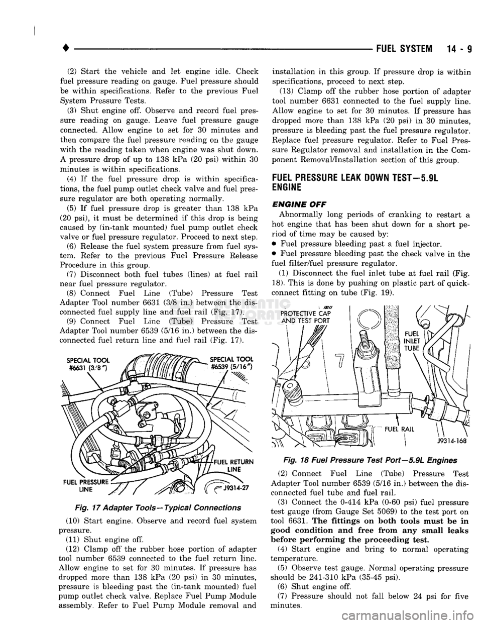
near fuel pressure regulator. (8) Connect Fuel Line (Tube) Pressure Test
Adapter Tool number 6631 (3/8 in.) between the dis connected fuel supply line and fuel rail (Fig. 17). (9) Connect Fuel Line (Tube) Pressure Test
Adapter Tool number 6539 (5/16 in.) between the dis
connected fuel return line and fuel rail (Fig. 17).
Fig. 17 Adapter Tools—Typical Connections
(10) Start engine. Observe and record fuel system
pressure.
(11) Shut engine off.
(12) Clamp off the rubber hose portion of adapter
tool number 6539 connected to the fuel return line.
Allow engine to set for 30 minutes. If pressure has
dropped more than 138 kPa (20 psi) in 30 minutes,
pressure is bleeding past the (in-tank mounted) fuel pump outlet check valve. Replace Fuel Pump Module assembly. Refer to Fuel Pump Module removal and installation in this group. If pressure drop is within
specifications, proceed to next step.
(13) Clamp off the rubber hose portion of adapter
tool number 6631 connected to the fuel supply line.
Allow engine to set for 30 minutes. If pressure has
dropped more than 138 kPa (20 psi) in 30 minutes,
pressure is bleeding past the fuel pressure regulator.
Replace fuel pressure regulator. Refer to Fuel Pres sure Regulator removal and installation in the Com
ponent Removal/Installation section of this group.
FUEL
PRESSURE
LEAK DOWN TEST—5.9L
ENGINE
ENGINE OFF Abnormally long periods of cranking to restart a
hot engine that has been shut down for a short pe
riod of time may be caused by:
• Fuel pressure bleeding past a fuel injector.
• Fuel pressure bleeding past the check valve in the
fuel filter/fuel pressure regulator.
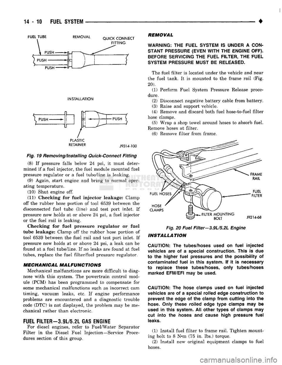
(1) Disconnect the fuel inlet tube at fuel rail (Fig.
18).
This is done by pushing on plastic part of quick-
connect fitting on tube (Fig. 19).
Fig. 18 Fuel Pressure Test Port—5.9L Engines
(2) Connect Fuel Line (Tube) Pressure Test
Adapter Tool number 6539 (5/16 in.) between the dis
connected fuel tube and fuel rail.
(3) Connect the 0-414 kPa (0-60 psi) fuel pressure
test gauge (from Gauge Set 5069) to the test port on
tool 6631. The fittings on both tools must be in good condition and free from any small leaks
before performing the proceeding test,
(4) Start engine and bring to normal operating
temperature.
(5) Observe test gauge. Normal operating pressure
should be 241-310 kPa (35-45 psi). (6) Shut engine off.
(7) Pressure should not fall below 24 psi for five
minutes.
Page 829 of 1502
FUEL
TUBE
REMOVAL
QUICK
CONNECT
FITTING
PUSH
PUSH PUSH
INSTALLATION
X
PUSH
/
•PUSH
PLASTIC
RETAINER
J9314-100
Fig. 19 Removing/Installing Quick-Connect Fitting (8) If pressure falls below 24 psi, it must deter
mined if a fuel injector, the fuel module mounted fuel
pressure regulator or a fuel tube/line is leaking. (9) Again, start engine and bring to normal oper
ating temperature.
(10) Shut engine off.
(11) Checking for fuel injector leakage: Clamp
off the rubber hose portion of tool 6539 between the
disconnected fuel tube (line) and test port inlet. If
pressure now holds at or above 24 psi, a fuel injector or the fuel rail is leaking.
Checking for fuel pressure regulator or fuel
tube leakage: Clamp off the rubber hose portion of
tool 6539 between the fuel rail and test port inlet. If
pressure now holds at or above 24 psi, a leak can be
found at a fuel tube/line. If no leaks are found at fuel
tubes,
replace the fuel filter/fuel pressure regulator.
MECHANICAL MALFUNCTIONS
Mechanical malfunctions are more difficult to diag
nose with this system. The powertrain control mod
ule (PCM) has been programmed to compensate for
some mechanical malfunctions such as incorrect cam
timing, vacuum leaks, etc. If engine performance
problems are encountered and a diagnostic trouble code (DTC) is not displayed, the problem may be me
chanical rather than electronic.
FUEL FILTER-3.9L/5.2L GAS ENGINE
For diesel engines, refer to Fuel/Water Separator
Filter in the Diesel Fuel Injection—Service Proce
dures section of this group.
REMOVAL
WARNING:
THE
FUEL
SYSTEM
IS
UNDER
A
CON
STANT
PRESSURE
(EVEN
WITH
THE
ENGINE
OFF).
BEFORE
SERVICING
THE
FUEL FILTER,
THE
FUEL
SYSTEM
PRESSURE
MUST
BE
RELEASED.
The fuel filter is located under the vehicle and near
the fuel tank. It is mounted to the frame rail (Fig.
20). (1) Perform Fuel System Pressure Release proce
dure.
(2) Disconnect negative battery cable from battery.
(3) Raise and support vehicle.
(4) Remove and discard both fuel hose-to-fuel filter
hose clamps. (5) Wrap a shop towel around hoses to absorb fuel.
Remove hoses at filter. (6) Remove filter from frame.
FUEL
HOSES
HOSE
CLAMPS
.
FILTER
MOUNTING
BOLT
FUEL
FILTER
J9214-68
Fig.
20
Fuel
Filter—3.9U5.2L
Engine
INSTALLATION
CAUTION:
The
tubes/hoses used
on
fuel
injected
vehicles
are of a
special construction. This
is due
to
the
higher
fuel
pressures
and the
possibility
of
contaminated
fuel
in
this system.
If it is
necessary
to replace these tubes/hoses, only tubes/hoses marked EFM/EFI
may be
used.
CAUTION:
The
hose clamps used
on
fuel
injected
vehicles
are of a
special rolled edge construction
to
prevent
the
edge
of the
clamp from cutting into
the
hose.
Only these rolled edge
type
clamps
may be
used
in
this system.
All
other types
of
clamps
may
cut into
the
hoses
and
cause high pressure
fuel
leaks.
(1) Install fuel filter to frame rail. Tighten mount
ing bolt to 8 N»m (75 in. lbs.) torque. (2) Install new original equipment clamps to fuel
hoses.
Page 830 of 1502
•
FUEL SYSTEM
14-11 (3)
Install hoses
to
filter. Tighten clamps
to 1 N*m
(10 in. lbs.)
torque. (4) Lower vehicle.
(5)
Connect battery cable
to
battery.
(6) Start engine
and
check
for
leaks.
FUEL
FILTER—5.9L
GAS ENGINE
For diesel engines, refer
to
Fuel/Water Separator
Filter
in the
Diesel Fuel Injection—Service Proce
dures section
of
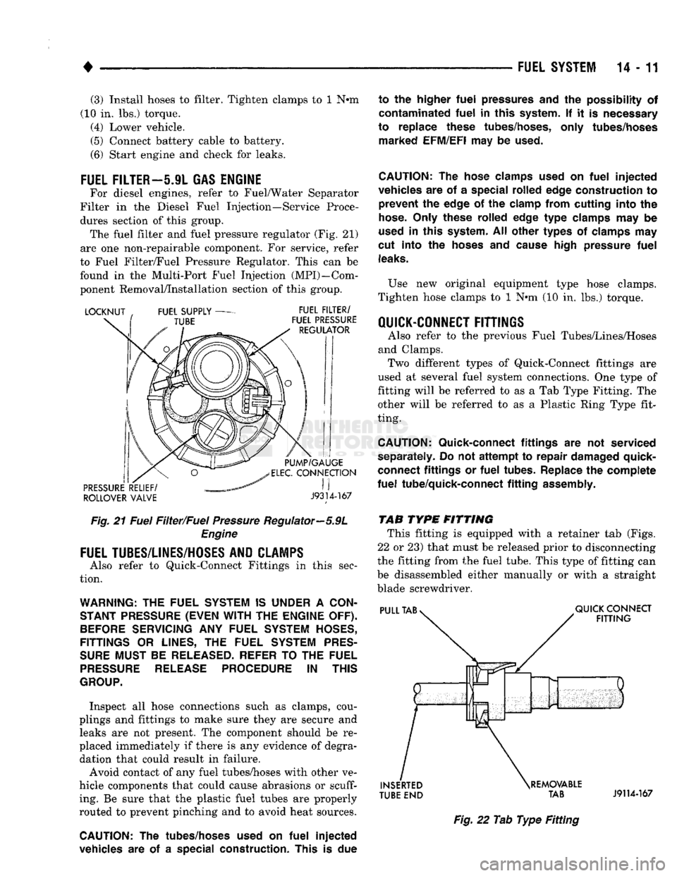
this group. The fuel filter
and
fuel pressure regulator
(Fig. 21)
are
one
non-repairable component.
For
service, refer
to Fuel Filter/Fuel Pressure Regulator. This
can be
found
in the
Multi-Port Fuel Injection (MPI)—Com
ponent Removal/Installation section
of
this group.
ROLLOVER VALVE
J9314-167
Fig.
21
Fuel Filter/Fuel Pressure Regulator—5.9L Engine
FUEL
TUBES/LINES/HOSES
AND CLAMPS
Also refer
to
Quick-Connect Fittings
in
this sec
tion.
WARNING:
THE
FUEL
SYSTEM
IS
UNDER
A
CON
STANT
PRESSURE
(EVEN WITH
THE
ENGINE
OFF).
BEFORE
SERVICING
ANY
FUEL
SYSTEM
HOSES,
FITTINGS
OR
LINES,
THE
FUEL
SYSTEM
PRES
SURE
MUST
BE
RELEASED-
REFER
TO
THE
FUEL
PRESSURE
RELEASE
PROCEDURE
IN
THIS
GROUP.
Inspect
all
hose connections such
as
clamps, cou
plings
and
fittings
to
make sure they
are
secure
and
leaks
are not
present.
The
component should
be re
placed immediately
if
there
is any
evidence
of
degra dation that could result
in
failure.
Avoid contact
of any
fuel tubes/hoses with other
ve
hicle components that could cause abrasions
or scuff
ing.
Be
sure that
the
plastic fuel tubes
are
properly
routed
to
prevent pinching
and to
avoid heat sources.
CAUTION:
The
tubes/hoses used
on
fuel
injected
vehicles
are of a
special construction. This
is due
to
the
higher
fuel
pressures
and the
possibility
of
contaminated
fuel
in
this system.
If it is
necessary
to replace these tubes/hoses, only tubes/hoses marked EFM/EFI
may
be
used.
CAUTION:
The
hose clamps used
on
fuel
injected
vehicles
are of a
special rolled edge construction
to
prevent
the
edge
of the
clamp from cutting into
the
hose.
Only these rolled edge
type
clamps
may be
used
in
this system.
All
other types
of
clamps
may
cut into
the
hoses
and
cause high pressure
fuel
leaks.
Use
new
original equipment type hose clamps.
Tighten hose clamps
to 1 N*m (10 in. lbs.)
torque.
QUICK-CONNECT FITTINGS
Also refer
to the
previous Fuel Tubes/Lines/Hoses
and Clamps. Two different types
of
Quick-Connect fittings
are
used
at
several fuel system connections.
One
type
of
fitting will
be
referred
to as a Tab
Type Fitting.
The
other will
be
referred
to as a
Plastic Ring Type fit
ting.
CAUTION:
Quick-connect fittings
are not
serviced
separately.
Do not
attempt
to
repair damaged quick-
connect fittings
or
fuel
tubes. Replace
the
complete
fuel
tube/quick-connect
fitting
assembly.
TAB
TYPE
FITTING This fitting
is
equipped with
a
retainer
tab
(Figs.
22
or
23) that must
be
released prior
to
disconnecting
the fitting from
the
fuel tube. This type
of
fitting
can
be disassembled either manually
or
with
a
straight
blade screwdriver.
TUBE
END TAB
J9114-167
Fig.
22 Tab
Type
Fitting
Page 834 of 1502
FUEL
DELIVERY—DIESEL
ENGINE
INDEX
page
Fuel Gauge Sending Unit Module
15
General Information
15
Manual
Shut Down Lever
. . 17
page
Mechanical
Lift
Pump
15
Quick
Connect Fittings—Except
Chassis
Fuel Tubes
17
GENERAL
INFORMATION
The fuel system of the 5.9L turbo-diesel engine
consists of the:
• Fuel tank • Low and high pressure fuel supply lines
• Mechanical lift pump
• Fuel/water separator filter
• Fuel heater
• Fuel injection pump • Fuel injectors
• Fuel return lines For information regarding fuel requirements of the
5.9L turbo diesel engine, refer to the Fuel Require
ments—Diesel Engines paragraph at the front of this group.
MECHANICAL
LIFT
PUMP
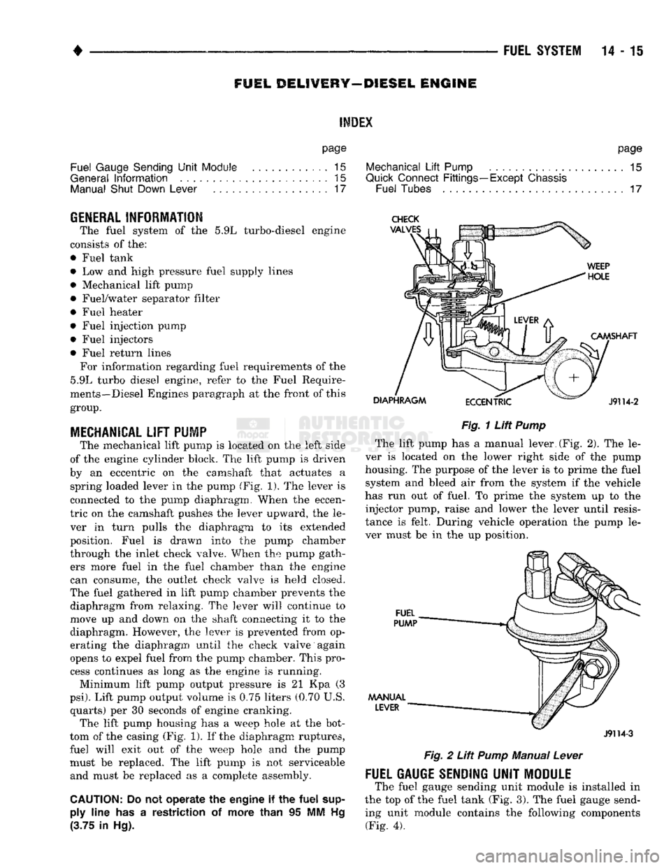
The mechanical lift pump is located on the left side
of the engine cylinder block. The lift pump is driven
by an eccentric on the camshaft that actuates a spring loaded lever in the pump (Fig. 1). The lever is
connected to the pump diaphragm. When the eccen
tric on the camshaft pushes the lever upward, the le ver in turn pulls the diaphragm to its extended
position. Fuel is drawn into the pump chamber
through the inlet check valve. When the pump gath ers more fuel in the fuel chamber than the engine
can consume, the outlet check valve is held closed.
The fuel gathered in lift pump chamber prevents the diaphragm from relaxing. The lever will continue to
move up and down on the shaft connecting it to the
diaphragm. However, the lever is prevented from op
erating the diaphragm until the check valve again
opens to expel fuel from the pump chamber. This pro cess continues as long as the engine is running.
Minimum lift pump output pressure is 21 Kpa (3
psi).
Lift pump output volume is 0.75 liters (0.70 U.S. quarts) per 30 seconds of engine cranking. The lift pump housing has a weep hole at the bot
tom of the casing (Fig. 1). If the diaphragm ruptures,
fuel will exit out of the weep hole and the pump
must be replaced. The lift pump is not serviceable and must be replaced as a complete assembly.
CAUTION:
Do not
operate
the
engine
if the
fuel
supply
line
has a
restriction
of
more than
95 MM Hg
(3.75
in Hg).
Fig.
1
Lift
Pump
The lift pump has a manual lever.(Fig. 2). The le
ver is located on the lower right side of the pump
housing. The purpose of the lever is to prime the fuel system and bleed air from the system if the vehicle
has run out of fuel. To prime the system up to the injector pump, raise and lower the lever until resis
tance is felt. During vehicle operation the pump le
ver must be in the up position.
J9114-3
Fig.
2
Lift
Pump
Manual
Lever
FUEL GAUGE SENDING
UNIT
MODULE
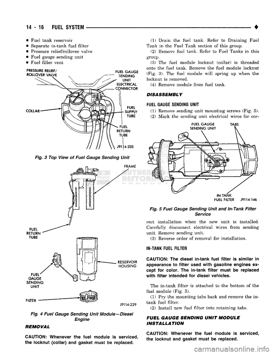
The fuel gauge sending unit module is installed in
the top of the fuel tank (Fig. 3). The fuel gauge send ing unit module contains the following components (Fig. 4).
Page 835 of 1502
14-16 FUEL SYSTEM
• • Fuel tank reservoir
• Separate in-tank fuel filter
• Pressure relief/rollover valve
• Fuel gauge sending unit
• Fuel filler vent
Fig. 3 Top View of Fuel Gauge Sending Unit
J9114-229
Fig. 4 Fuel Gauge Sending Unit Module--Diesel Engine
REMOVAL
CAUTION:
Whenever
the
fuel
module
is
serviced,
the
locknut
(collar)
and
gasket must
be
replaced. (1)
Drain the fuel tank. Eefer to Draining Fuel
Tank in the Fuel Tank section of this group.
(2) Remove fuel tank. Refer to Fuel Tanks in this
group.
(3)
The fuel module locknut (collar) is threaded
onto the fuel tank. Remove the fuel module locknut (Fig. 3). The fuel module will spring up when the
locknut is removed. (4) Remove module from fuel tank.
DISASSEMBLY
FUEL
GAUGE SENDING
UNIT
(1) Remove sending unit mounting screws (Fig. 5).
(2) Mark the sending unit electrical wires for cor-
FUEL
GAUGE TABS
IN-TANK
FUEL FILTER
J9114-146
Fig. 5 Fuel Gauge Sending Unit and In-Tank Filter Service
rect installation when the new unit is installed. Carefully disconnect electrical wires from sending
unit. Remove sending unit.
(3)
Reverse order of removal for installation.
IN-TANK
FUEL FILTER
CAUTION:
The
diesel in-tank
fuel
filter is
similar
in
appearance
to filter
used
with
gasoline engines
ex
cept
for
color.
The
in-tank
filter
must
be
replaced
with
filter
intended
for
diesel vehicles.
The in-tank filter is attached to the bottom of the
fuel module (Fig. 5). (1) Pry the mounting tabs back and remove the in-
tank fuel filter. (2) Install new fuel filter into retaining tabs.
FUEL GAUGE SENDING UNIT MODULE INSTALLATION
CAUTION:
Whenever
the
fuel
module
is
serviced,
the locknut
and
gasket must
be
replaced.
Page 859 of 1502
14
- 40
FUEL
SYSTEM
• • Park/Neutral switch (gear indicator signal—auto,
trans,
only)
• Oxygen (02) sensor(s) Based on these inputs, the following occurs:
• Voltage is applied to the fuel injectors with the
PCM. The PCM will then adjust the injector pulse
width by turning the ground circuit to each individ
ual injector on and off.
• The PCM monitors the 02 sensor(s) input and ad
justs air-fuel ratio. It also adjusts engine idle speed through the idle air control (IAC) motor.
• The PCM adjusts ignition timing by turning the
ground path to the coil on and off.
• The PCM operates the A/C compressor clutch
through the clutch relay. This happens if A/C has
been selected by the vehicle operator and requested
by the A/C thermostat.
ACCELERATION MODE
This is an Open Loop mode. The powertrain control
module (PCM) recognizes an abrupt increase in
throttle position or MAP pressure as a demand for
increased engine output and vehicle acceleration.
The PCM increases injector pulse width in response
to increased throttle opening.
DECELERATION MODE
When the engine is at operating temperature, this
is an Open Loop mode. During hard deceleration, the
powertrain control module (PCM) receives the follow ing inputs.
• Air conditioning select signal (if equipped)
• Air conditioning request signal (if equipped)
• Battery voltage
• Engine coolant temperature sensor
• Crankshaft position sensor
• Intake manifold charge air temperature sensor
• Manifold absolute pressure (MAP) sensor
• Throttle position sensor (TPS)
• Camshaft position sensor signal (in the distributor)
• Park/Neutral switch (gear indicator signal —auto,
trans,
only)
If the vehicle is under hard deceleration with the
proper rpm and closed throttle conditions, the PCM
will ignore the oxygen sensor input signal. The PCM
will enter a fuel cut-off strategy in which it will not supply battery voltage to the injectors. If a hard de
celeration does not exist, the PCM will determine the
proper injector pulse width and continue injection.
Based on the above inputs, the PCM will adjust en
gine idle speed through the idle air control (IAC) mo
tor. The PCM adjusts ignition timing by turning the
ground path to the coil on and off.
The PCM opens the ground circuit to the A/C
clutch relay to disengage the A/C compressor clutch.
This is done until the vehicle is no longer under de
celeration (if the A/C system is operating).
WIDE OPEN
THROTTLE
MODE
This is an Open Loop mode. During wide open
throttle operation, the powertrain control module (PCM) receives the following inputs.
• Battery voltage
• Crankshaft position sensor
• Engine coolant temperature sensor
• Intake manifold charge air temperature sensor
• Manifold absolute pressure (MAP) sensor
• Throttle position sensor (TPS) • Camshaft position sensor signal (in the distributor) During wide open throttle conditions, the following
occurs:
• Voltage is applied to the fuel injectors with the
powertrain control module (PCM). The PCM will
then control the injection sequence and injector pulse
width by turning the ground circuit to each individ ual injector on and off. The PCM ignores the oxygen sensor input signal and provides a predetermined amount of additional fuel. This is done by adjusting
injector pulse width.
• The PCM adjusts ignition timing by turning the
ground path to the coil on and off.
• The PCM opens the ground circuit to the A/C
clutch relay to disengage the A/C compressor clutch.
This will be done for approximately 15 seconds (if the air conditioning system is operating).
If the vehicle has a manual transmission, the up
shift light is operated by the PCM.
IGNITION
SWITCH
OFF
MODE
When ignition switch is turned to OFF position,
the PCM stops operating the injectors, ignition coil,
ASD relay and fuel pump relay.
THROTTLE
BODY
Filtered air from the air cleaner enters the intake
manifold through the throttle body (Fig. 18). Fuel does not enter the intake manifold through the throt
tle body. Fuel is sprayed into the manifold by the fuel injectors. The throttle body is mounted on the
intake manifold. It contains an air control passage (Fig. 19) controlled by an idle air control (IAC) mo
tor. The air control passage is used to supply air for idle conditions. A throttle valve (plate) is used to supply air for above idle conditions. The throttle position sensor (TPS), idle air control
(IAC) motor and manifold absolute pressure sensor
(MAP) are attached to the throttle body. The acceler
ator pedal cable, speed control cable and transmis
sion control cable (when equipped) are connected to
the throttle arm. A (factory adjusted) set screw is used to mechani
cally limit the position of the throttle body throttle
plate. Never attempt to adjust the engine idle speed using this screw. All idle speed functions are
controlled by the PCM.