1993 DODGE TRUCK seats
[x] Cancel search: seatsPage 722 of 1502
•
5.9L
(DIESEL)
ENGINE
9 - 117 Inspect the end of the valve stem for flatness.
If required, resurface the valve end.
VALVE
GRINDING
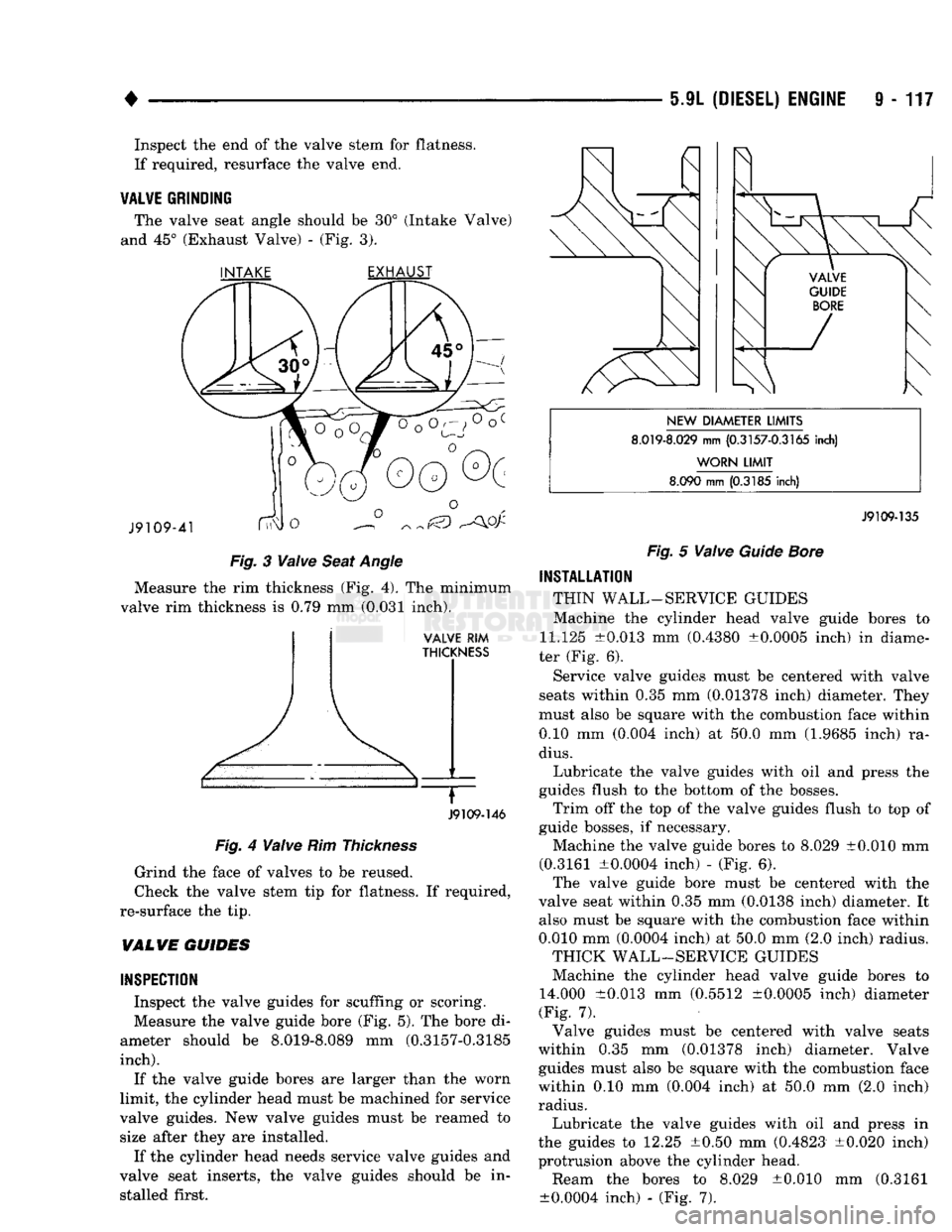
The valve seat angle should be 30° (Intake Valve)
and 45° (Exhaust Valve) - (Fig. 3). INTAKE
EXHAUST
J9109-41
^ 00 ^
Fig.
3
Valve
Seat
Angle
Measure the rim thickness (Fig. 4). The minimum
valve rim thickness is 0.79 mm (0.031 inch).
VALVE
RIM
THICKNESS
J9109-146
Fig.
4
Valve
Rim
Thickness
Grind the face of valves to be reused.
Check the valve stem tip for flatness. If required,
re-surface the tip.
VALWE
GUIDES
INSPECTION
Inspect the valve guides for scuffing or scoring.
Measure the valve guide bore (Fig. 5). The bore di
ameter should be 8.019-8.089 mm (0.3157-0.3185
inch).
If the valve guide bores are larger than the worn
limit, the cylinder head must be machined for service
valve guides. New valve guides must be reamed to size after they are installed.
If the cylinder head needs service valve guides and
valve seat inserts, the valve guides should be in stalled first.
NEW
DIAMETER
LIMITS
8.019-8.029
mm
(0.3157-0.3165
inch)
WORN
LIMIT
8.090
mm
(0.3185
inch)
J9109-135
Fig.
5
Valve
Guide
Bore
INSTALLATION
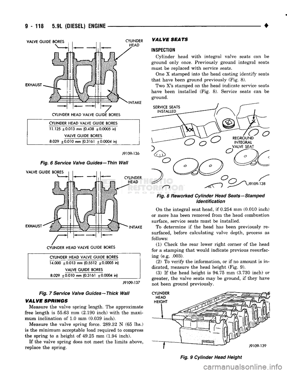
THIN WALL-SERVICE GUIDES Machine the cylinder head valve guide bores to
11.125 ±0.013 mm (0.4380 ±0.0005 inch) in diame
ter (Fig. 6).
Service valve guides must be centered with valve
seats within 0.35 mm (0.01378 inch) diameter. They
must also be square with the combustion face within 0.10 mm (0.004 inch) at 50.0 mm (1.9685 inch) ra
dius.
Lubricate the valve guides with oil and press the
guides flush to the bottom of the bosses. Trim off the top of the valve guides flush to top of
guide bosses, if necessary. Machine the valve guide bores to
8.029
±0.010 mm
(0.3161 ±0.0004 inch) - (Fig. 6). The valve guide bore must be centered with the
valve seat within 0.35 mm (0.0138 inch) diameter. It also must be square with the combustion face within
0.010 mm (0.0004 inch) at 50.0 mm (2.0 inch) radius. THICK WALL-SERVICE GUIDES
Machine the cylinder head valve guide bores to
14.000 ±0.013 mm (0.5512 ±0.0005 inch) diameter
(Fig. 7). Valve guides must be centered with valve seats
within 0.35 mm (0.01378 inch) diameter. Valve guides must also be square with the combustion face
within 0.10 mm (0.004 inch) at 50.0 mm (2.0 inch) radius. Lubricate the valve guides with oil and press in
the guides to 12.25 ±0.50 mm (0.4823 ±0.020 inch) protrusion above the cylinder head. Ream the bores to
8.029
±0.010 mm (0.3161
±0.0004 inch) - (Fig. 7).
Page 723 of 1502
i - 118 5.9L
(DIESEL) ENGINE
VALVE GUIDE
BORES
EXHAUST CYLINDER
HEAD
INTAKE
CYLINDER HEAD VALVE GUIDE
BORES
CYLINDER HEAD VALVE GUIDE
BORES
11.125
±0.013 mm (0.438 ± 0.0005 in)
VALVE GUIDE
BORES
8.029
±0.010
mm
(0.3161 ±0.0004 in)
J9109-136
Fig.
6
Service
Valve
Guides—Thin
Wall
VALVE GUIDE
BORES
CYLINDER HEAD
EXHAUST INTAKE
CYLINDER HEAD VALVE GUIDE
BORES
CYLINDER HEAD VALVE GUIDE
BORES
14.000 ±0.013
mm
(0.5512 ± 0.0005 in)
VALVE GUIDE
BORES
8.029
±0.010
mm
(0.3161 ±0.0004 in)
J9109-137
Fig.
7
Service
Valve
Guides—Thick
Wall
VALVE
SPRINGS
Measure
the
valve spring length.
The
approximate
free length
is
55.63
mm
(2.190 inch) with
the
maxi mum inclination
of 1.0 mm
(0.039 inch).
Measure
the
valve spring force. 289.32
N (65 lbs.)
is
the
minimum acceptable load required
to
compress
the spring
to a
height
of
49.25
mm (1.94
inch). If
the
valve spring does
not
meet
the
limits above,
replace
the
spring.
VALVE
SEATS
INSPECTION
Cylinder head with integral valve seats
can be
ground only once. Previously ground integral seats
must
be
replaced with service seats. One
X
stamped into
the
head casting identify seats
that have been ground previously
(Fig. 8).
Two
X's
stamped
on the
head indicate service seats
have been installed
(Fig. 8).
Service seats
can be
ground.
SERVICE SEATS
INSTALLED
n
o
REGROUND INTEGRAL
VALVE SEAT
J9109-138
Fig.
8
Reworked
Cylinder Head
Seats—Stamped
Identification
On
the
integral seat head,
if
0.254
mm
(0.010 inch)
or more
has
been removed from
the
head combustion surface, service seats must
be
installed. To determine
if the
head
has
been previously
re
surfaced, before calculating valve depth, process
as
follows:
(1) Check
the
rear lower right corner
of the
head
for
a
stamping that would indicate previous resurfac ing
(e.g.
.003).
(2)
To
verify
the
information,
or if no
amount
is in
dicated, measure
the
head height
(Fig. 9).
(3)
If the
head height
is
94.75
mm
(3.730 inch)
or
greater,
the
valve seats
may be
ground,
if
they have
not been ground previously.
CYLINDER
HEAD
HEIGHT
J9109-139
Fig.
9
Cylinder Head Height
Page 724 of 1502
•
5.9L (DIESEL) ENGINE
9 - 119
INTEGRAL VALWE SEAT GRINDING
After resurfacing the valves and determining that
all valves meet specifications, install the valves in
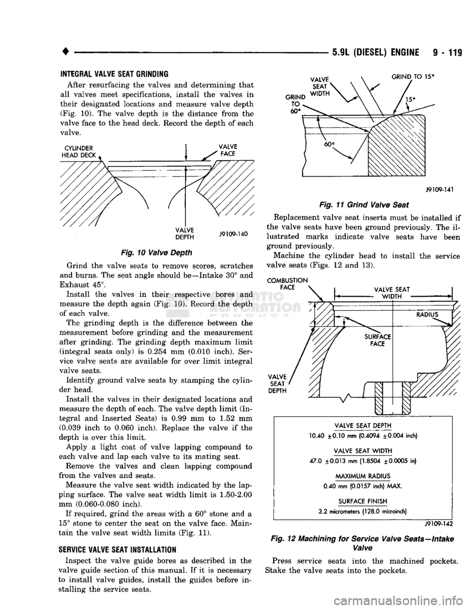
their designated locations and measure valve depth (Fig. 10). The valve depth is the distance from the
valve face to the head deck. Record the depth of each valve.
CYLINDER
HEAD DECK GRIND
TO 15°
VALVE
DEPTH
J9109-140
Fig.
10
Valve
Depth
Grind the valve seats to remove scores, scratches
and burns. The seat angle should be—Intake 30° and
Exhaust 45°. Install the valves in their respective bores and
measure the depth again (Fig. 10). Record the depth
of each valve.
The grinding depth is the difference between the
measurement before grinding and the measurement after grinding. The grinding depth maximum limit (integral seats only) is 0.254 mm (0.010 inch). Ser
vice valve seats are available for over limit integral
valve seats.
Identify ground valve seats by stamping the cylin
der head.
Install the valves in their designated locations and
measure the depth of each. The valve depth limit (In
tegral and Inserted Seats) is 0.99 mm to 1.52 mm (0.039 inch to 0.060 inch). Replace the valve if the
depth is over this limit.
Apply a light coat of valve lapping compound to
each valve and lap each valve to its mating seat.
Remove the valves and clean lapping compound
from the valves and seats.
Measure the valve seat width indicated by the lap
ping surface. The valve seat width limit is
1.50-2.00
mm (0.060-0.080 inch).
If required, grind the areas with a 60° stone and a
15° stone to center the seat on the valve face. Main
tain the valve seat width limits (Fig. 11).
SERVICE
VALVE
SEAT
INSTALLATION
Inspect the valve guide bores as described in the
valve guide section of this manual. If it is necessary
to install valve guides, install the guides before in stalling the service seats.
J9109-141
Fig.
11
Grind
Valve
Seat
Replacement valve seat inserts must be installed if
the valve seats have been ground previously. The il lustrated marks indicate valve seats have been
ground previously.
Machine the cylinder head to install the service
valve seats (Figs. 12 and 13).
COMBUSTION FACE VALVE
SEAT
DEPTH VALVE SEAT DEPTH
10.40 ±0.10 mm
(0.4094
±0.004
inch)
VALVE SEAT
WIDTH
47.0
±0.013
mm
(1.8504
±
0.0005
in)
MAXIMUM
RADIUS
0.40 mm
(0.0157
inch) MAX.
SURFACE FINISH
3.2 micrometers
(128.0
microinch)
J9109-142
Fig.
12
Machining
for
Service
Valve
Seats—Intake
Valve
Press service seats into the machined pockets.
Stake the valve seats into the pockets.
Page 725 of 1502
9
- 120 5.9L
(DIESEL)
ENGINE
•
COMBUSTION
FACE
VALVE
SEAT
DEPTH
'///
A
I
V
1
VALVE
SEAT
DEPTH
10.20 ±0.10 mm
(0.4015
±0.004
inch)
VALVE
SEAT
WIDTH
43.65
±0.013
mm
(1.7185
±0.0005
in)
MAXIMUM
RADIUS
0.40 mm
(0.0157
inch) MAX.
SURFACE
FINISH
3.2 micrometers
(128.0
microinch)
J9109-143
Fig.
13
Machining
for
Service
Valve
Seats—Exhaust
Valve
SERVICE VALVE SEAT GRINDING
Install the valves in their designated location and
measure the valve depth. The valve depth is the dis
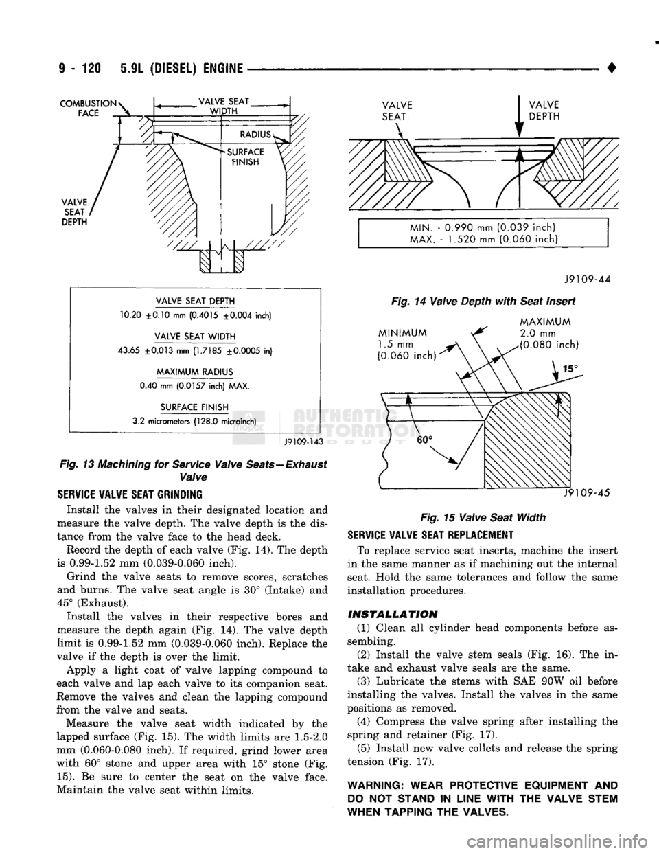
tance from the valve face to the head deck. Record the depth of each valve (Fig. 14). The depth
is 0.99-1.52 mm (0.039-0.060 inch).
Grind the valve seats to remove scores, scratches
and burns. The valve seat angle is 30° (Intake) and
45° (Exhaust). Install the valves in their respective bores and
measure the depth again (Fig. 14). The valve depth
limit is 0.99-1.52 mm (0.039-0.060 inch). Replace the
valve if the depth is over the limit.
Apply a light coat of valve lapping compound to
each valve and lap each valve to its companion seat.
Remove the valves and clean the lapping compound
from the valve and seats.
Measure the valve seat width indicated by the
lapped surface (Fig. 15). The width limits are
1.5-2.0
mm (0.060-0.080 inch). If required, grind lower area
with 60° stone and upper area with 15° stone (Fig.
15).
Be sure to center the seat on the valve face.
Maintain the valve seat within limits.
MIN.
-
0.990
mm
(0.039
inch)
MAX.
- 1.520 mm
(0.060
inch)
J9109-44
Fig.
14
Valve
Depth
with
Seat
Insert
MINIMUM
1.5 mm
(0.060
inch)
MAXIMUM
2.0
mm
(0.080
inch)
J9109-45
Fig.
15
Valve
Seat
Width
SERVICE VALVE SEAT REPLACEMENT
To replace service seat inserts, machine the insert
in the same manner as if machining out the internal
seat. Hold the same tolerances and follow the same
installation procedures.
INSTALLATION
(1) Clean all cylinder head components before as
sembling.
(2) Install the valve stem seals (Fig. 16). The in
take and exhaust valve seals are the same.
(3) Lubricate the stems with SAE 90W oil before
installing the valves. Install the valves in the same
positions as removed.
(4) Compress the valve spring after installing the
spring and retainer (Fig. 17).
(5) Install new valve collets and release the spring
tension (Fig. 17).
WARNING: WEAR PROTECTIVE EQUIPMENT
AND
DO
NOT
STAND
IN
LINE
WITH
THE VALVE STEM
WHEN TAPPING THE VALVES.
Page 751 of 1502
9
- 148 5.9L
(DIESEL) ENGINE
• Make sure the idler gear pin is installed in the lo
cating bore in the cylinder block. (2) Install the pump. Tighten the oil pump mount
ing bolts in two steps and in the sequence shown (Fig. 2).
• Step
1—Tighten
to 5 N«m (44 in. lbs.) torque.
• Step 2-Tighten to 24 N*m (18 ft. lbs.) torque. (3) The back plate on the pump seats against the
bottom of the bore in the cylinder block. When the
pump is correctly installed, the flange on the pump will not touch the cylinder block.
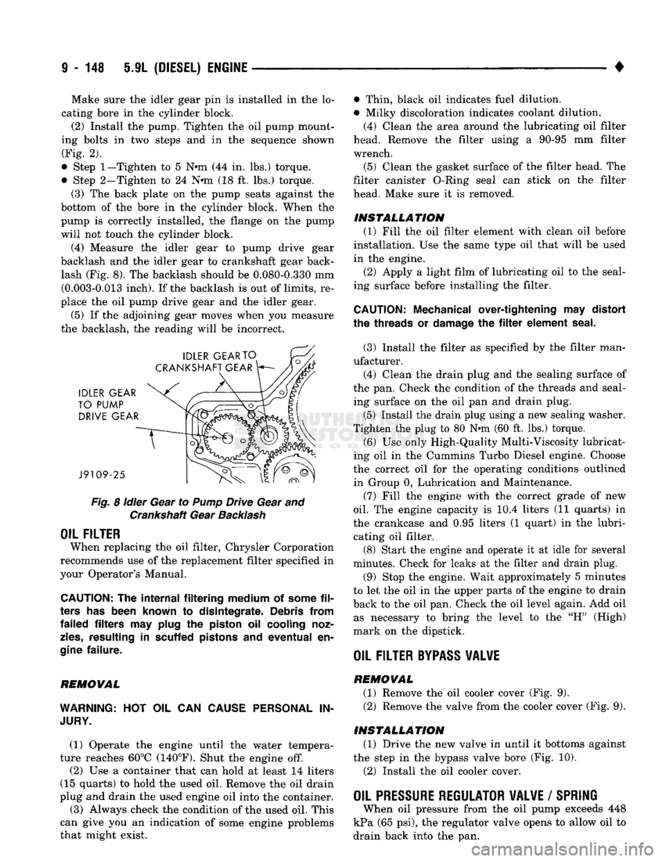
(4) Measure the idler gear to pump drive gear
backlash and the idler gear to crankshaft gear back lash (Fig. 8). The backlash should be 0.080-0.330 mm (0.003-0.013 inch). If the backlash is out of limits, re
place the oil pump drive gear and the idler gear.
(5) If the adjoining gear moves when you measure
the backlash, the reading will be incorrect.
Fig.
8
idler
Gear to
Pump
Drive Gear and Crankshaft Gear
Backlash
OIL FILTER
When replacing the oil filter, Chrysler Corporation
recommends use of the replacement filter specified in
your Operator's Manual.
CAUTION:
The
internal filtering medium
of
some
fil
ters
has
been known
to
disintegrate. Debris from
failed filters
may
plug
the
piston
oil
cooling noz
zles,
resulting
in
scuffed pistons
and
eventual
en
gine
failure.
REMOVAL
WARNING:
HOT OIL CAN
CAUSE PERSONAL
IN
JURY.
(1) Operate the engine until the water tempera
ture reaches 60°C (140°F). Shut the engine off.
(2) Use a container that can hold at least 14 liters
(15 quarts) to hold the used oil. Remove the oil drain
plug and drain the used engine oil into the container.
(3) Always check the condition of the used oil. This
can give you an indication of some engine problems
that might exist. • Thin, black oil indicates fuel dilution.
• Milky discoloration indicates coolant dilution.
(4) Clean the area around the lubricating oil filter
head. Remove the filter using a 90-95 mm filter
wrench.
(5) Clean the gasket surface of the filter head. The
filter canister O-Ring seal can stick on the filter
head. Make sure it is removed.
INSTALLATION (1) Fill the oil filter element with clean oil before
installation. Use the same type oil that will be used
in the engine.
(2) Apply a light film of lubricating oil to the seal
ing surface before installing the filter.
CAUTION:
Mechanical over-tightening
may
distort
the threads
or
damage
the filter
element seal.
(3) Install the filter as specified by the filter man
ufacturer. (4) Clean the drain plug and the sealing surface of
the pan. Check the condition of the threads and seal ing surface on the oil pan and drain plug.
(5) Install the drain plug using a new sealing washer.
Tighten the plug to 80 N-m (60 ft. lbs.) torque.
(6) Use only High-Quality Multi-Viscosity lubricat
ing oil in the Cummins Turbo Diesel engine. Choose
the correct oil for the operating conditions outlined in Group 0, Lubrication and Maintenance.
(7) Fill the enginfe with the correct grade of new
oil.
The engine capacity is i0.4 liters (11 quarts) in
the crankcase and 0.95 liters (1 quart) in the lubri cating oil filter. (8) Start the engine and operate it at idle for several
minutes. Check for leaks at the filter and drain plug.
(9) Stop the engine. Wait approximately 5 minutes
to let the oil in the upper parts of the engine to drain
back to the oil pan. Check the oil level again. Add oil as necessary to bring the level to the "H" (High)
mark on the dipstick.
OIL FILTER
BYPASS
VALWE
REMOVAL
(1) Remove the oil cooler cover (Fig. 9). (2) Remove the valve from the cooler cover (Fig. 9).
INSTALLATION (1) Drive the new valve in until it bottoms against
the step in the bypass valve bore (Fig. 10).
(2) Install the oil cooler cover.
OIL PRESSURE REGULATOR VALVE
/
SPRING
When oil pressure from the oil pump exceeds 448
kPa (65 psi), the regulator valve opens to allow oil to
drain back into the pan.
Page 986 of 1502
•
STEERING
19 - 25
PITMAN
SHAFT AND SIDE COVER REPLACEMENT
REMOVE (1) Remove steering gear from vehicle. Refer to
Power Steering Gear Replacement in this section. (2) Remove pitman arm from steering gear. Refer
to Pitman Arm Removal in the Steering Linkage sec
tion.
(3) Rotate stub shaft back and forth to drain power
steering fluid.
DISASSEMBLE
• Clean exposed end of pitman shaft and housing.
• Clean pitman shaft spline with a wire brush.
(1) Remove preload adjuster nut.
(2) Rotate stub shaft with socket to center gear.
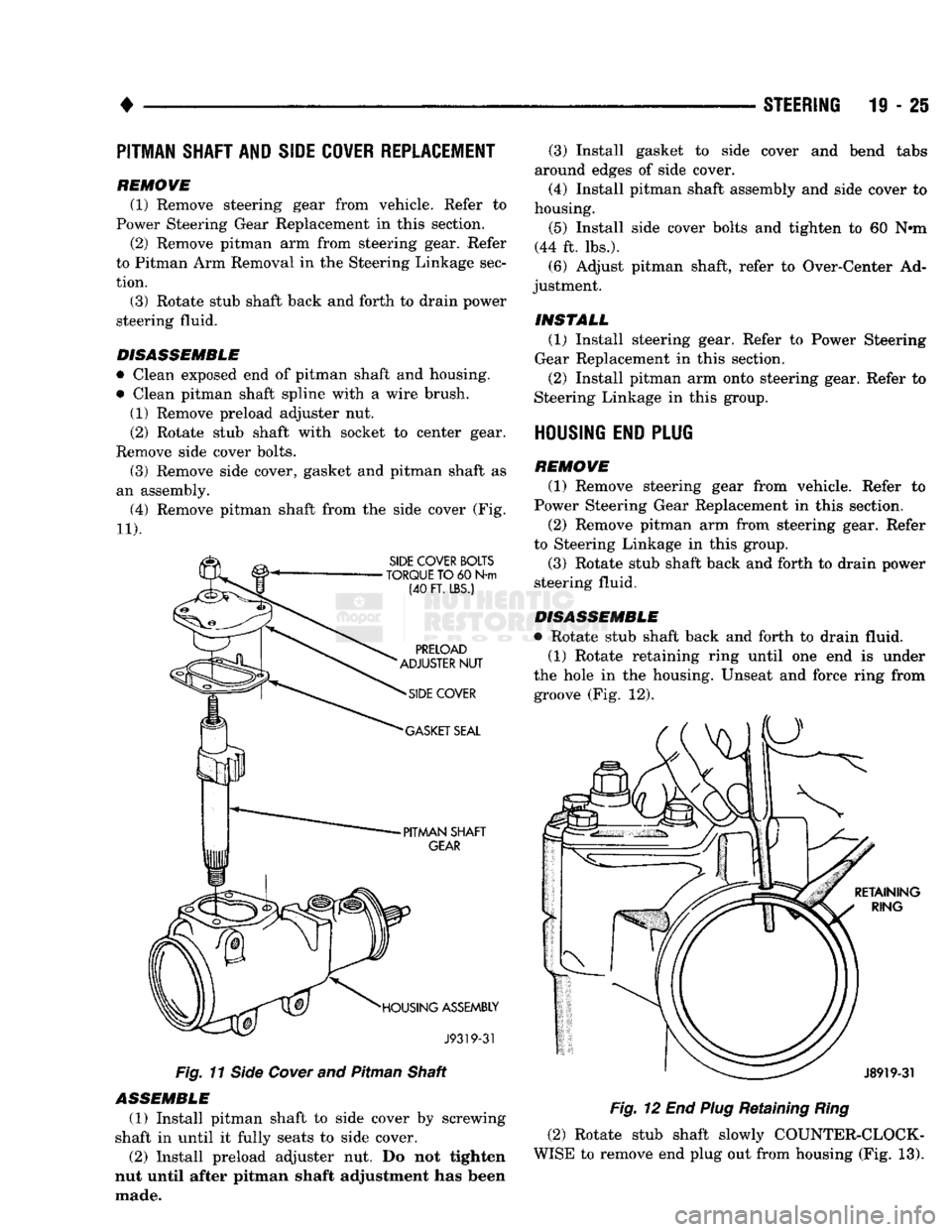
Remove side cover bolts. (3) Remove side cover, gasket and pitman shaft as
an assembly.
(4) Remove pitman shaft from the side cover (Fig.
11). Fig.
11
Side
Cover
and Pitman Shaft
ASSEMBLE
(1) Install pitman shaft to side cover by screwing
shaft in until it fully seats to side cover. (2) Install preload adjuster nut. Do not tighten
nut until after pitman shaft adjustment has been
made. (3) Install gasket to side cover and bend tabs
around edges of side cover.
(4) Install pitman shaft assembly and side cover to
housing.
(5) Install side cover bolts and tighten to 60 N»m
(44 ft. lbs.). (6) Adjust pitman shaft, refer to Over-Center Ad
justment.
INSTALL (1) Install steering gear. Refer to Power Steering
Gear Replacement in this section.
(2) Install pitman arm onto steering gear. Refer to
Steering Linkage in this group.
HOUSING END PLUG
REMOVE (1) Remove steering gear from vehicle. Refer to
Power Steering Gear Replacement in this section.
(2) Remove pitman arm from steering gear. Refer
to Steering Linkage in this group.
(3) Rotate stub shaft back and forth to drain power
steering fluid.
DISASSEMBLE
• Rotate stub shaft back and forth to drain fluid. (1) Rotate retaining ring until one end is under
the hole in the housing. Unseat and force ring from groove (Fig. 12).
Fig.
12 End
Plug
Retaining
Ring
(2) Rotate stub shaft slowly COUNTER-CLOCK
WISE to remove end plug out from housing (Fig. 13).
Page 1031 of 1502
21
- 30
NV4500
TRANSMISSION
OVERHAUL
•
SNAP
RING
FIRST
-GEAR
BEARING
MAINSHAFT
SYNCHRO
HUB
J9221-176
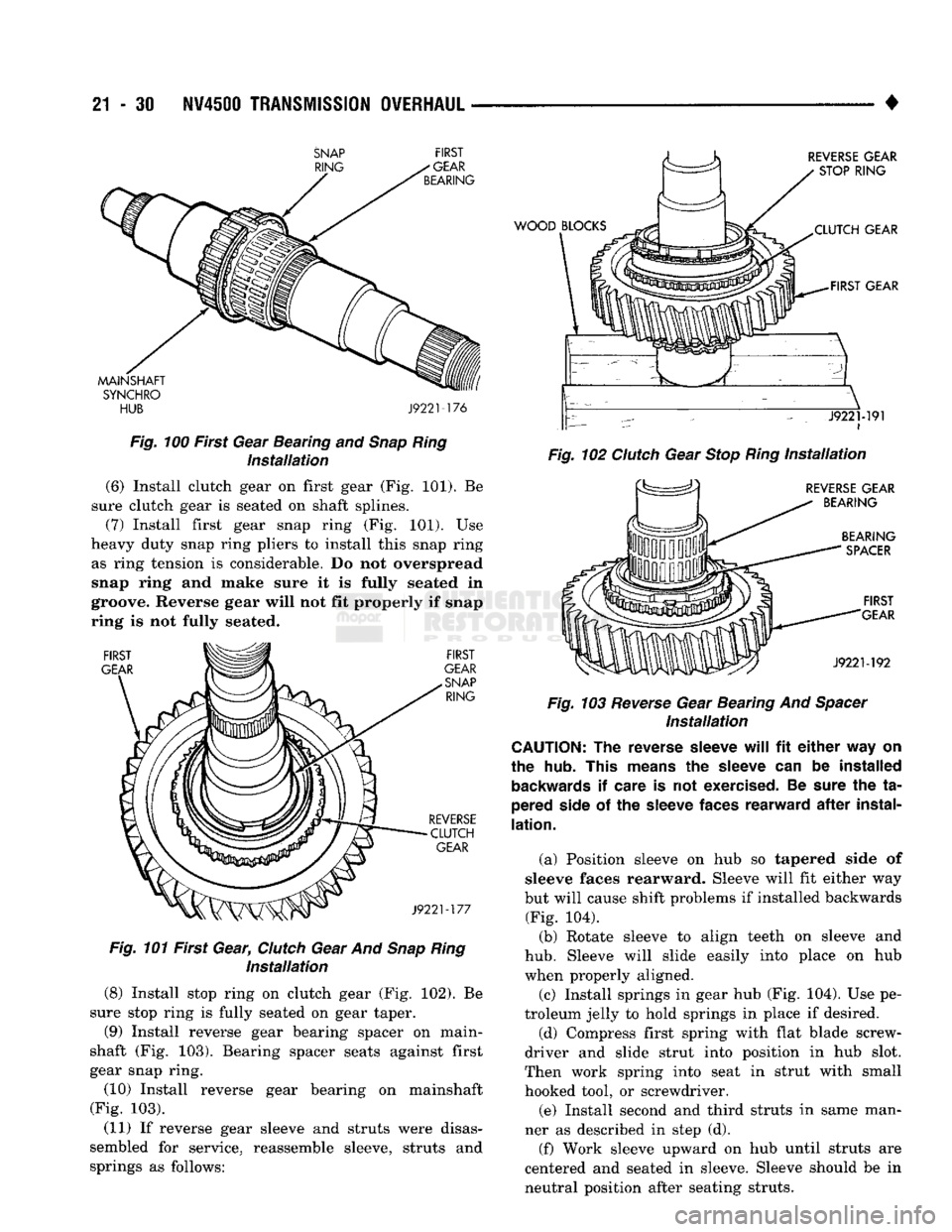
Fig.
100 First Gear Bearing
and
Snap
Ring
Installation
(6) Install clutch gear
on
first gear
(Fig. 101). Be
sure clutch gear
is
seated
on
shaft splines. (7) Install first gear snap ring
(Fig. 101). Use
heavy duty snap ring pliers
to
install this snap ring as ring tension
is
considerable.
Do not
overspread
snap ring
and
make sure
it is
fully seated
in
groove. Reverse gear will
not fit
properly
if
snap
ring
is not
fully seated.
FIRST
GEAR
FIRST
GEAR
SNAP
RING
REVERSE
CLUTCH
GEAR
J9221-177
Fig.
101 First Gear,
Clutch
Gear
And
Snap
Ring
Installation
(8) Install stop ring
on
clutch gear
(Fig. 102). Be
sure stop ring
is
fully seated
on
gear taper.
(9) Install reverse gear bearing spacer
on
main-
shaft
(Fig. 103).
Bearing spacer seats against first
gear snap ring. (10) Install reverse gear bearing
on
mainshaft
(Fig.
103).
(11)
If
reverse gear sleeve
and
struts were disas
sembled
for
service, reassemble sleeve, struts
and
springs
as
follows:
WOOD
BLOCKS
REVERSE
GEAR
STOP
RING
XLUTCH
GEAR
-FIRST
GEAR
\-
-• ~ • - - x J9221-191
i
Fig.
102
Clutch
Gear
Stop
Ring
Installation
REVERSE
GEAR
BEARING
BEARING
SPACER
FIRST
GEAR
J9221-192
Fig.
103
Reverse
Gear Bearing
And
Spacer
Installation
CAUTION:
The
reverse
sleeve
will
fit
either
way
on
the
hub.
This
means
the
sleeve
can be
installed
backwards
if
care
is not
exercised.
Be
sure
the ta
pered
side
of the
sleeve
faces
rearward
after
instal
lation.
(a) Position sleeve
on hub so
tapered side
of
sleeve faces rearward. Sleeve will
fit
either
way
but will cause shift problems
if
installed backwards (Fig.
104).
(b) Rotate sleeve
to
align teeth
on
sleeve
and
hub.
Sleeve will slide easily into place
on hub
when properly aligned. (c) Install springs
in
gear
hub (Fig. 104). Use pe
troleum jelly
to
hold springs
in
place
if
desired.
(d) Compress first spring with flat blade screw
driver
and
slide strut into position
in hub
slot.
Then work spring into seat
in
strut with small
hooked tool,
or
screwdriver.
(e) Install second
and
third struts
in
same man
ner
as
described
in
step
(d).
(f) Work sleeve upward
on hub
until struts
are
centered
and
seated
in
sleeve. Sleeve should
be in
neutral position after seating struts.
Page 1066 of 1502
•
OUTPUT
SHAFT
"
PILOT
BEARING
J9321-303
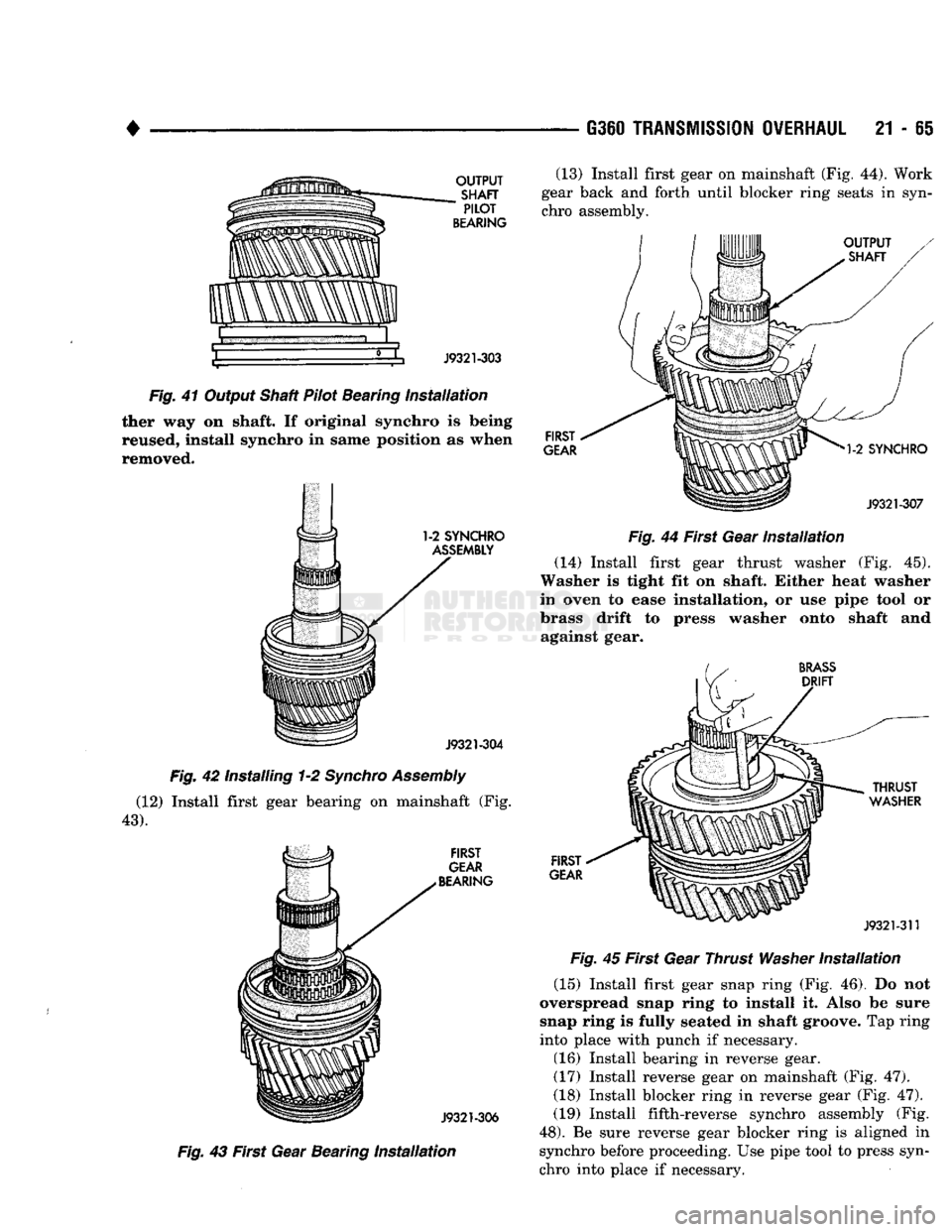
Fig.
41 Output Shaft Pilot Bearing
Installation
ther way on shaft. If original synchro is being
reused, install synchro in same position as when
removed.
Fig.
42 Installing 1-2
Synchro
Assembly
(12) Install first gear bearing on mainshaft (Fig.
43). FIRST
GEAR
BEARING
J9321-306
Fig.
43 First Gear Bearing
Installation
G360
TRANSMISSION OVERHAUL
21 - 65
(13) Install first gear on mainshaft (Fig. 44). Work
gear back and forth until blocker ring seats in syn
chro assembly.
Fig.
44 First Gear
Installation
(14) Install first gear thrust washer (Fig. 45).
Washer is tight fit on shaft. Either heat washer
in oven to ease installation, or use pipe tool or
brass drift to press washer onto shaft and against gear.
FIRST
GEAR Fig.
45 First Gear Thrust
Washer
Installation
(15) Install first gear snap ring (Fig. 46). Do not
overspread snap ring to install it. Also be sure snap ring is fully seated in shaft groove. Tap ring
into place with punch if necessary.
(16) Install bearing in reverse gear.
(17) Install reverse gear on mainshaft (Fig. 47).
(18) Install blocker ring in reverse gear (Fig. 47). (19) Install fifth-reverse synchro assembly (Fig.
48).
Be sure reverse gear blocker ring is aligned in synchro before proceeding. Use pipe tool to press syn
chro into place if necessary.