1993 DODGE TRUCK seats
[x] Cancel search: seatsPage 1138 of 1502
IN-VEHICLE
SERVICE-32RH/38RH/37RH/42RH/46RH
21 - 137
SPECIAL TOOL GOVERNOR SUPPORT
AND
PARKING GEAR RH78
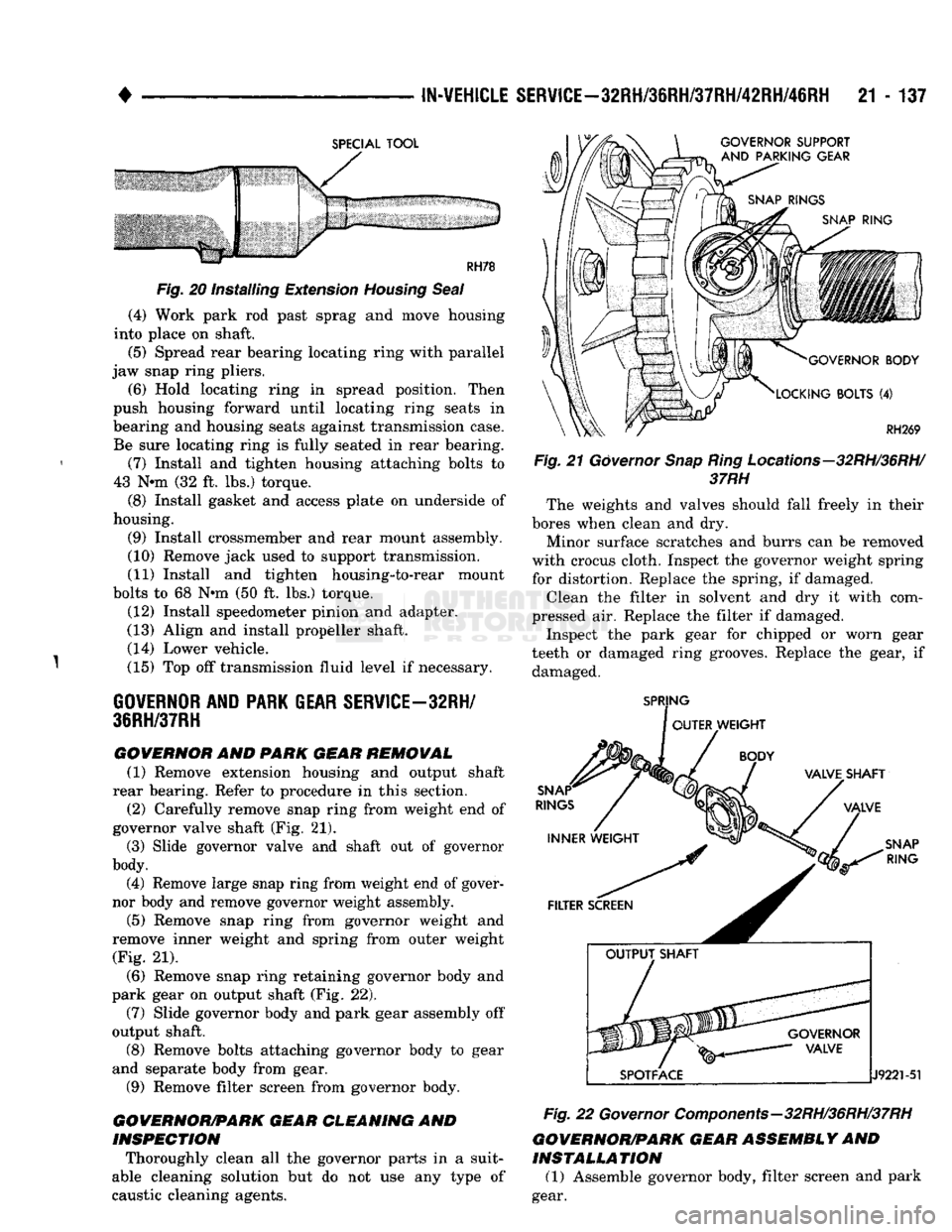
Fig. 20 installing Extension Housing
Seal
(4) Work park rod past sprag and move housing
into place on shaft.
(5) Spread rear bearing locating ring with parallel
jaw snap ring pliers. (6) Hold locating ring in spread position. Then
push housing forward until locating ring seats in
bearing and housing seats against transmission case. Be sure locating ring is fully seated in rear bearing.
(7) Install and tighten housing attaching bolts to
43 Nnn (32 ft. lbs.) torque.
(8) Install gasket and access plate on underside of
housing.
(9) Install crossmember and rear mount assembly.
(10) Remove jack used to support transmission.
(11) Install and tighten housing-to-rear mount
bolts to 68 Nnn (50 ft. lbs.) torque. (12) Install speedometer pinion and adapter.
(13) Align and install propeller shaft. (14) Lower vehicle.
(15) Top off transmission fluid level if necessary.
GOVERNOR AND PARK GEAR SERVICE—32RH/
3SRH/37RH
GOVERNOR
AND
PARK
GEAR
REMOVAL
(1) Remove extension housing and output shaft
rear bearing. Refer to procedure in this section.
(2) Carefully remove snap ring from weight end of
governor valve shaft (Fig. 21). (3) Slide governor valve and shaft out of governor
body. (4) Remove large snap ring from weight end of gover
nor body and remove governor weight assembly.
(5) Remove snap ring from governor weight and
remove inner weight and spring from outer weight (Fig. 21).
(6) Remove snap ring retaining governor body and
park gear on output shaft (Fig. 22). (7) Slide governor body and park gear assembly off
output shaft. (8) Remove bolts attaching governor body to gear
and separate body from gear. (9) Remove filter screen from governor body.
GOVERNOR/PARK
GEAR
CLEANING
AND
INSPECTION
Thoroughly clean all the governor parts in a suit
able cleaning solution but do not use any type of
caustic cleaning agents.
GOVERNOR BODY
LOCKING BOLTS
(4)
Fig.
21
Governor
Snap
Ring
Locations-
37RH
RH269
-32RH/36RH/
The weights and valves should fall freely in their
bores when clean and dry.
Minor surface scratches and burrs can be removed
with crocus cloth. Inspect the governor weight spring for distortion. Replace the spring, if damaged. Clean the filter in solvent and dry it with com
pressed air. Replace the filter if damaged. Inspect the park gear for chipped or worn gear
teeth or damaged ring grooves. Replace the gear, if damaged.
SPRING
OUTER WEIGHT
SNAP
RINGS
INNER WEIGHT VALVET SHAFT
VALVE
SNAP
RING
FILTER SCREEN
J9221-51
Fig.
22
Governor
Components—32RH/36RH/37RH
GOVERNOR/PARK
GEAR
ASSEMBLY
AND
INSTALLATION
(1) Assemble governor body, filter screen and park
gear.
Page 1183 of 1502
21
- 182
TRANSMISSION OVERHAUL—32RH
• VAL VE
BODY
ASSEMBL
Y
CAUTION:
Do not
force
the valves or plugs
into
place
during
reassembly. If the valve body
bores,
valves
and plugs are
free
of
distortion
or burrs, the
valve body components should all slide
into
place
easily. In
addition,
do not
overtighten
the
transfer
plate
and valve body
screws
during
reassembly.
Overtightening
can
distort
the valve body
resulting
in valve sticking,
cross
leakage and
unsatisfactory
operation. Tighten valve body
screws
to recom mended
torque
only.
(1) Lubricate valve body bores, valves and plugs
with transmission fluid.
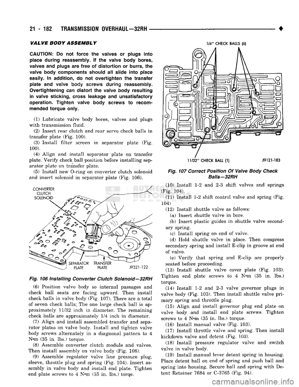
(2) Insert rear clutch and rear servo check balls in
transfer plate (Fig. 100).
(3) Install filter screen in separator plate (Fig.
100).
(4) Align and install separator plate on transfer
plate. Verify check ball position before installing sep arator plate on transfer plate.
(5) Install new O-ring on converter clutch solenoid
and insert solenoid in separator plate (Fig. 106). Fig. 106
Installing
Converter
Clutch
Solenoid—32RH
(6) Position valve body so internal passages and
check ball seats are facing upward. Then install
check balls in valve body (Fig. 107). There are a total
of seven check balls; The one large check ball is ap
proximately 11/32 inch in diameter. The remaining
check balls are approximately 1/4 inch in diameter.
(7) Align and install assembled transfer and sepa
rator plates on valve body. Install and tighten valve
body screws alternately in a diagnonal pattern to 4 N»m (35 in. lbs.) torque.
(8) Assemble converter clutch module and valves.
Then install assembly on valve body (Fig. 108).
(9) Assemble regulator valve line pressure plug,
sleeve, throttle plug and spring (Fig. 104). Insert as
sembly in valve body and install end plate. Tighten
end plate screws to 4 N»m (35 in. lbs.) torqe. 1/4"
CHECK
BALLS
(6)
11/32"
CHECK
BALL
(1) J912M83
Fig. 107
Correct
Position
Of
Valve
Body Check
Baiis-32RH
(10) Install 1-2 and 2-3 shift valves and springs
(Fig. 104).
(11) Install 1-2 shift control valve and spring (Fig.
104)
(12) Install shuttle valve as follows: (a) Insert shuttle valve in bore.
(b) Insert plastic guides in shuttle valve second
ary spring.
(c) Install spring on end of valve.
(d) Hold shuttle valve in place. Then compress
secondary spring and install E-clip in groove at end
of valve. (e) Verify that spring and E-clip are properly
seated before proceeding.
(13) Install shuttle valve cover plate (Fig. 103).
Tighten end plate screws to 4 N»m (35 in. lbs.)
torque.
(14) Install 1-2 and 2-3 valve governor plugs in
valve body (Fig. 103). Then install shuttle valve pri
mary spring and throttle plug.
(15) Align and install governor plug end plate on
valve body and install end plate screws. Tighten screws to 4 N*m (35 in. lbs.) torque.
(16) Install manual valve (Fig. 103).
(17) Install throttle valve and spring. Then install
kickdown valve and detent (Fig. 103).
(18) Install pressure regulator valve and switch
valve in valve body.
(19) Install manual lever detent spring in housing.
Place detent ball on end of spring and push ball and spring into housing. Secure ball and spring with De
tent Retainer 7684 or C-3765 (Fig. 94).
Page 1186 of 1502
•
TRANSMISSION
OVERHAUL—32RH
21-185
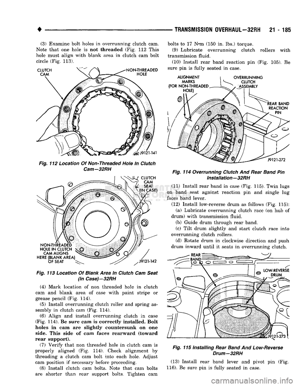
(3) Examine bolt holes in overrunning clutch cam.
Note that one hole is not threaded (Fig. 112 This
hole must align with blank area in clutch cam bolt circle (Fig. 113).
Fig.
113 Location Of
Blank
Area in
Clutch
Cam
Seat
(in
Case)-32RH
(4) Mark location of non threaded hole in clutch
cam and blank area of case with paint stripe or
grease pencil (Fig. 114).
(5) Install overrunning clutch roller and spring as
sembly in clutch cam (Fig. 114).
(6) Align and install overrunning clutch in case
(Fig. 114). Be sure cam is correctly installed. Bolt
holes in cam are slightly countersunk on one side. This side of cam faces rearward (toward
rear support).
(7) Verify that non threaded hole in clutch cam is
properly aligned (Fig. 114). Check alignment by threading a clutch cam bolt into each hole. Adjust cam position if necessary before proceeding.
(8) Install clutch cam bolts. Note that cam bolts
are shorter than rear support bolts. Tighten cam bolts to 17 N»m (150 in. lbs.) torque.
(9) Lubricate overrunning clutch rollers with
transmission fluid. (10) Install rear band reaction pin (Fig. 105). Be
sure pin is fully seated in case.
Fig.
114 Overrunning
Clutch
And Rear
Band
Pin Installation—32RH
(11) Install rear band in case (Fig. 115). Twin lugs
on band seat against reaction pin and single lug
faces band lever.
(12) Install low-reverse drum as follows (Fig. 115): (a) Lubricate overrunning clutch race (on hub of
drum) with transmission fluid. (b) Guide drum through rear band.
(c) Tilt drum slightly and start clutch race into
overrunning clutch rollers.
(d) Rotate drum in clockwise direction and push
drum inward until it seats in overrunning clutch.
Fig.
115 Installing Rear
Band
And
Low-Reverse
Drum—32RH
(13) Install rear band lever and pivot pin (Fig.
116).
Be sure pin is fully seated in case.
Page 1222 of 1502
•
TRANSMISSION
OVERHAUL—36RH/37RH
21 - 221 (3) Align and install separator plate on transfer
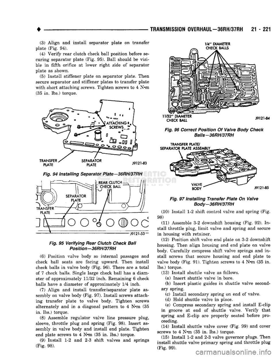
plate (Fig. 94). (4) Verify rear clutch check ball position before se
curing separator plate (Fig. 95). Ball should be visi
ble in fifth orifice at lower right side of separator plate as shown.
(5) Install stiffener plate on separator plate. Then
secure separator and stiffener plates to transfer plate
with short attaching screws. Tighten screws to 4 Nnn (35 in. lbs.) torque. 1/4"
DIAMETER
CHECK
BALLS
TRANSFER
PLATE
SEPARATOR
PLATE
J9121-83
Fig.
94 Installing Separator Plate—36RH/37RH f^-^. )
REAR CLUTCH-
J9121-53-
Fig.
95
Verifying
Rear
Clutch
Check
Ball
Position-36RH/37RH (6) Position valve body so internal passages and
check ball seats are facing upward. Then install
check balls in valve body (Fig. 96). There are a total
of 7 check balls. Single large check ball has a diam eter of approximately 11/32 inch. Remaining 6 check
balls have a diameter of approximately 1/4 inch.
(7) Align and install transfer/separator plate as
sembly on valve body (Fig. 97). Install screws attach
ing transfer plate to valve body. Tighten screws alternately and in a diagonal pattern to 4 Nnn (35
in. lbs.) torque.
(8) Assemble regulator valve line pressure plug,
sleeve, throttle plug and spring (Fig. 98). Insert as
sembly in valve body and install end plate. Tighten
end plate screws to 4 Nnn (35 in. lbs.) torque.
(9) Install 1-2 and 2-3 shift valves and springs
(Fig. 98).
11/32"
DIAMETER
CHECK
BALL
J9121-84
Fig.
96 Correct Position Of
Valve
Body Check
Balis-36RH/37RH
TRANSFER
PLATE/
SEPARATOR
PLATE ASSEMBLY
VALVE
BODY
J9121-85
Fig.
97 Installing Transfer
Plate
On
Valve
Body-36RH/37RH
(10) Install 1-2 shift control valve and spring (Fig.
98) (11) Assemble 3-2 downshift housing (Fig. 92). In
stall throttle plug, limit valve and spring and secure
in housing with retainer.
(12) Position shift valve end plate on 3-2 downshift
housing. Then align housing and end plate on valve
body. Carefully compress shift valve springs and in stall screws that secure housing and end plate to
valve body (Fig. 91). Tighten screws to 4 Nnn (35 in.
lbs.) torque.
(13) Install shuttle valve as follows. (a) Insert shuttle valve in bore.
(b) Insert plastic guides in shuttle valve second
ary spring. (c) Install secondary spring on end of valve.
(d) Hold shuttle valve in place.
(e) Compress secondary spring and install E-clip
in groove at end of shuttle valve. Verify that
spring and E-clip are properly seated before pro
ceeding. (14) Install shuttle valve cover (Fig. 99) and cover
screws to 4 Nnn (35 in. lbs.) torque. (15) Install 1-2 and 2-3 valve governor plugs. Then
install shuttle valve primary spring and throttle plug (Fig. 99).
Page 1265 of 1502
21
- 264
TRANSMISSION QVERHAUL-42RH
ADJUSTING
-
SCREW
AND
SWITCH
CONNECTOR
SEAL
J9321-226
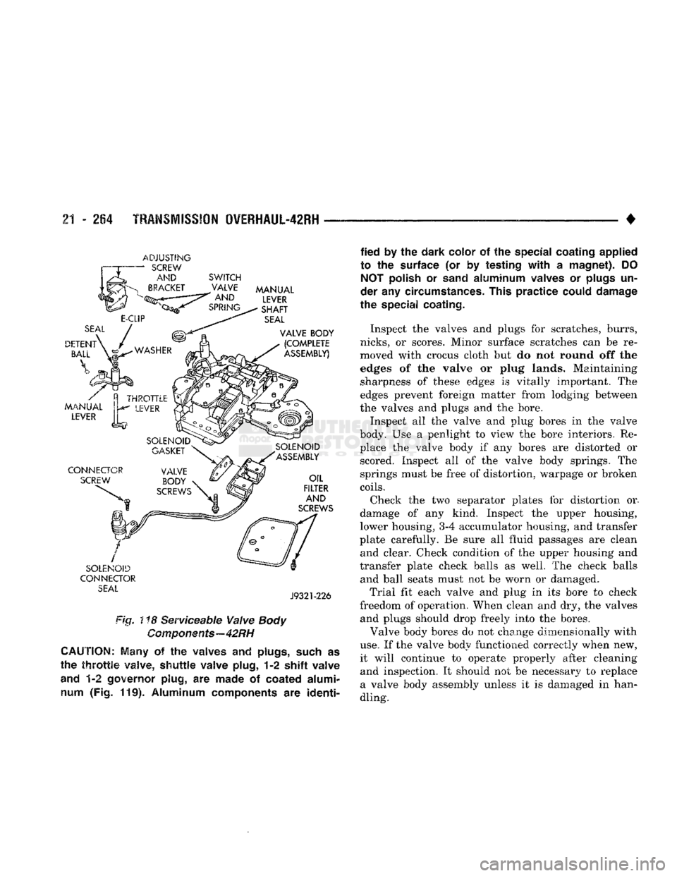
Fig. ! *8 Serviceable Valve
Body
Components—42RH
CAUTION;
Many
of the
waives
and
plugs,
such
as
the
throttle
valve,
shuttle
valve plug,
1-2 shift
valve
and
1-2
governor plug,
are
made
of
coated alumi num
(Fig. 119).
Aluminum components
are
identi
fied
by the
dark color
of the
special coating applied
to
the
surface
(or by
testing
with
a
magnet).
DO
NOT
polish
or
sand
aluminum valves
or
plugs
un
der
any
circumstances. This practice could damage
the special coating.
Inspect the valves and plugs for scratches, burrs,
nicks,
or scores. Minor surface scratches can be re
moved with crocus cloth but do not round off the
edges of the valve or plug lands. Maintaining sharpness of these edges is vitally important. The
edges prevent foreign matter from lodging between
the valves and plugs and the bore.
Inspect all the valve and plug bores in the valve
body. Use a penlight to view the bore interiors. Re place the valve body if any bores are distorted or scored. Inspect all of the valve body springs. The
springs must be free of distortion, warpage or broken
coils.
Check the two separator plates for distortion or.
damage of any kind. Inspect the upper housing,
lower housing,
3-4
accumulator housing, and transfer
plate carefully. Be sure all fluid passages are clean and clear. Check condition of the upper housing and
transfer plate check balls as well. The check balls and ball seats must not be worn or damaged.
Trial fit each valve and plug in its bore to check
freedom of operation. When clean and dry, the valves and plugs should drop freely into the bores.
Valve body bores do not change dimensionally with
use.
If the valve body functioned correctly when new,
it will continue to operate properly after cleaning and inspection. It should not be necessary to replace
a valve body assembly unless it is damaged in han
dling.
Page 1267 of 1502
21
- 266
TRANSMISSION
OWERHAUL-42RH
•
VALVE
BODY REASSEMBLY
CAUTION:
Do not
force
valves or plugs
into
place
during
reassembly. If the valve body
bores,
valves
and
plugs are
free
of
distortion
or burrs, the valve body components should all slide
into
place easily.
In
addition,
do not
overtighten
the
transfer
plate
and
valve body
screws
during
reassembly. Over
tightening
can
distort
the
housings
resulting
in
valve sticking,
cross
leakage and unsatisfactory op
eration.
Tighten valve body
screws
to recom mended
torque
only.
Lower
Housing
Assembly
(Fig. 116)
(1) Lubricate valves, springs, and the housing
valve and plug bores with transmission fluid.
(2) Install 3-4 timing valve spring and valve in
lower housing.
(3) Install 3-4 shuttle valve in lower housing.
Press valve inward and install E-clip on end of valve
to secure it in housing. (4) Install 3-4 shuttle valve spring and throttle
plug in housing.
(5)
Install timing valve end plate. Tighten end
plate screws to 4 N«m (35 in. lbs.) torque.
(6) Install 3-4 shift valve and spring.
(7) Install converter clutch valve, spring and plug.
(8) Install converter clutch timing valve and
spring.
3-4
Accumulator
Assembly
(Fig. 117) (1) Lubricate accumulator piston, seals and hous
ing piston bore with transmission fluid. (2) Install new seal rings on accumulator piston.
(3) Install piston and spring in housing. (4) Install end plate on housing.
Transfer Plate
Assembly
(1) Install rear clutch check ball in transfer plate
(Fig. 110). (2) Install filter screen in upper housing separator
plate (Fig. 109). (3) Align and position upper housing separator
plate on transfer plate (Fig. 109).
(4) Install brace plate (Fig. 108). Tighten brace at
taching screws to 4 N«m (35 in. lbs.) torque. (5) Install remaing separator plate attaching
screws. Tighten screws to 4 Nrn (35 in. lbs.) torque.
Assembling
Upper And Lower
Housings
(1) Position upper housing so internal passages
and check ball seats are facing upward. Then install
check balls in housing (Fig. 111). Seven check balls are used. The single large check ball is approxi
mately 8.7 mm (11/32 in.) diameter. The remaining 6 check balls are approximately 6.3 mm (1/4 in.) in di ameter. (2) Position transfer plate assembly on upper hous
ing (Fig. 120).
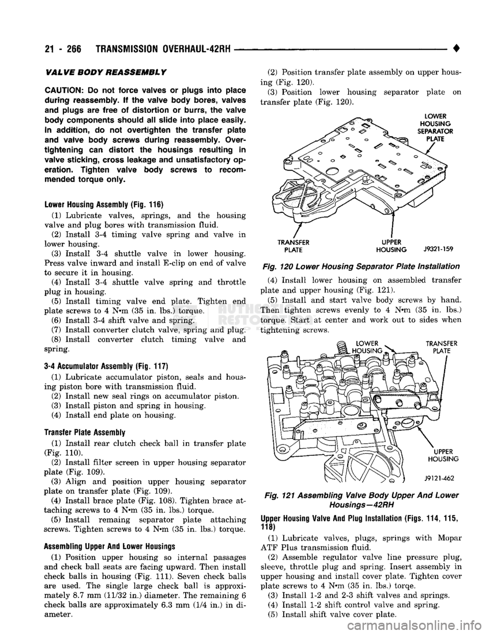
(3) Position lower housing separator plate on
transfer plate (Fig. 120).
TRANSFER
UPPER
PLATE
HOUSING
J932M59
Fig.
120
Lower
Housing
Separator
Plate
Installation
(4) Install lower housing on assembled transfer
plate and upper housing (Fig. 121).
(5) Install and start valve body screws by hand.
Then tighten screws evenly to 4
N*m
(35 in. lbs.) torque. Start at center and work out to sides when
tightening screws.
Fig.
121
Assembling
Valve
Body
Upper And
Lower
Housings—42
RH
Upper
Housing
Valve And
Plug
Installation
(Figs.
114, 115,
118)
(1) Lubricate valves, plugs, springs with Mopar
ATF Plus transmission fluid.
(2) Assemble regulator valve line pressure plug,
sleeve, throttle plug and spring. Insert assembly in
upper housing and install cover plate. Tighten cover
plate screws to 4
N*m
(35 in. lbs.) torqe.
(3) Install 1-2 and 2-3 shift valves and springs.
(4) Install 1-2 shift control valve and spring.
(5) Install shift valve cover plate.
Page 1272 of 1502
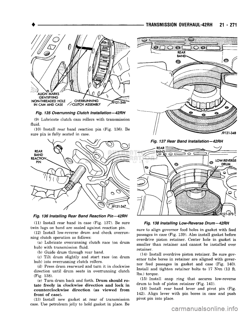
•
Fig.
135 Overrunning
Clutch
Installation—42RH (9) Lubricate clutch cam rollers with transmission
fluid.
(10) Install rear band reaction pin (Fig. 136). Be
sure pin is fully seated in case.
Fig.
136 Installing Rear
Band
Reaction
Pin—42RH
(11) Install rear band in case (Fig. 137). Be sure
twin lugs on band are seated against reaction pin.
(12) Install low-reverse drum and check overrun
ning clutch operation as follows:
(a) Lubricate overrunning clutch race (on drum
hub) with transmission fluid.
(b) Guide drum through rear band.
(c) Tilt drum slightly and start race (on drum
hub) into overrunning clutch rollers. (d) Press drum rearward and turn it in clockwise
direction until drum seats in overrunning clutch (Fig. 138). (e) Turn drum back and forth. Drum should ro
tate freely in clockwise direction and lock in
counterclockwise direction (as viewed from
front of case). (13) Install new gasket at rear of transmission
case.
Use petroleum jelly to hold gasket in place. Be
TRANSMISSION
0VERHAUL-42RH
21 - 271
Fig.
137 Rear
Band
Installation—42RH
Fig.
138 Installing
Low-Reverse
Drum—42RH
sure to align governor feed holes in gasket with feed
passages in case (Fig. 139). Also install gasket before overdrive piston retainer. Center hole in gasket is
smaller than retainer and cannot be installed over
retainer.
(14) Install overdrive piston retainer. Be sure gov
ernor tube bores in retainer are aligned with gover
nor feed passages in gasket and case (Fig. 140).
Install and tighten retainer bolts to 17 N#m (13 ft. lbs.) torque.
(15) Install snap ring that secures low-reverse
drum to hub of piston retainer (Fig. 141). (16) Install rear band lever and pivot pin (Fig.
142).
Align lever with pin bores in case and push
pivot pin into place.
Page 1311 of 1502
21
- 310
TRANSMISSION 0VERHAUL-46RH
• plate carefully. Be sure all fluid passages are clean
and clear. Check condition of the upper housing and
transfer plate check balls as well. The check balls and ball seats must not be worn or damaged.
Trial fit each valve and plug in its bore to check
freedom of operation. When clean and dry, the valves and plugs should drop freely into the bores.
Valve body bores do not change dimensionally with
use.
If the valve body functioned correctly when new,
it will continue to operate properly after cleaning
and inspection. It should not be necessary to replace
a valve body assembly unless it is damaged in han
dling.
VALWE
BODY BEASSEMBLY
CAUTION; Do not
force valves
or
plugs
into place
during reassembly.
If the
valve body bores, valves
and
plugs
are
free
of
distortion
or
burrs,
the
valve
body
components should
all
slide into place easily.
In addition,
do not
overtighten
the
transfer
plate
and
valve body screws during reassembly. Over
tightening
can
distort
the
housings
resulting
in
valve sticking,
cross
leakage
and
unsatisfactory
op
eration. Tighten valve body screws
to
recom mended torque only.
Lower Housing Assembly (Fig.
116)
(1) Lubricate valves, springs, and the housing
valve and plug bores with Mopar ATF Plus, or
Dexron II® transmission fluid. (2) Install 3-4 timing valve spring and valve in
lower housing. (3) Install 3-4 shuttle valve in lower housing.
Press valve inward and install E-clip on end of valve
to secure it in housing.
(4) Install 3-4 shuttle valve spring and throttle
plug in housing. (5) Install timing valve end plate. Tighten end
plate screws to 4 N»m (35 in. lbs.) torque.
(6) Install 3-4 shift valve and spring.
(7) Install converter clutch valve, spring and plug.
(8) Install converter clutch timing valve and
spring.
3-4 Accumulator
Assembly
(Fig.
117) (1) Lubricate accumulator piston, seals and hous
ing piston bore with ATF Plus, or Dexron II®. (2) Install new seal rings on accumulator piston.
(3) Install piston and spring in housing.
(4) Install end plate on housing.
Transfer Plate Assembly
(1) Install rear clutch check ball in transfer plate
(Fig. 110). (2) Install filter screen in upper housing separator
plate (Fig. 109). (3) Align and position upper housing separator
plate on transfer plate (Fig. 109).
(4) Install brace plate (Fig. 108). Tighten brace at
taching screws to 4 Nnn (35 in. lbs.) torque. (5) Install remaining separator plate attaching
screws. Tighten screws to 4 N*m (35 in. lbs.) torque.