1993 DODGE TRUCK seats
[x] Cancel search: seatsPage 1313 of 1502
21
- 312 TRANSMISSION OWERHAUL-46RH
•
Assembling
Upper
And
Lower
Housings
(1) Position upper housing so internal passages
and check ball seats are facing upward. Then install
check balls in housing (Fig. 111). Seven check balls are used. The single large check ball is approxi
mately 8.7 mm (11/32 in.) diameter. The remaining 6
check balls are approximately 6.3 mm (1/4 in.) in di ameter.
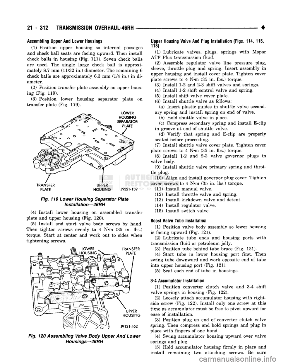
(2) Position transfer plate assembly on upper hous
ing (Fig. 119).
(3) Position lower housing separator plate on
transfer plate (Fig. 119).
TRANSFER
UPPER PLATE HOUSING
J932M59
Fig. 119 Lower Housing Separator Plate Installation—46RH
(4) Install lower housing on assembled transfer
plate and upper housing (Fig. 120).
(5)
Install and start valve body screws by hand.
Then tighten screws evenly to 4 N*m (35 in. lbs.)
torque. Start at center and work out to sides when
tightening screws. Fig. 120 Assembling Valve Body Upper And Lower
Housings—46RH
Upper
Housing
Valve
And
Plug
Installation
(Figs.
114,111,
118)
(1) Lubricate valves, plugs, springs with Mopar
ATF Plus transmission fluid.
(2) Assemble regulator
valve
line pressure plug,
sleeve, throttle plug and spring. Insert assembly in
upper housing and install cover plate. Tighten cover
plate screws to 4 N»m (35 in. lbs.) torque.
(3) Install 1-2 and 2-3 shift valves and springs.
(4) Install 1-2 shift control valve and spring.
(5) Install shift valve cover plate. (6) Install shuttle valve as follows: (a) Insert plastic guides in shuttle valve second
ary spring and install spring on end of valve.
(b) Hold shuttle valve in place.
(c) Compress secondary spring and install E-clip
in groove at end of shuttle valve. (d) Verify that spring and E-clip are properly
seated before proceeding. (7) Install shuttle valve cover plate. Tighten cover
plate screws to 4 N®m (35 in. lbs.) torque.
(8) Install 1-2 and 2-3 valve governor plugs in
valve body. (9) Install shuttle valve primary spring and throt
tle plug. (10) Align and install governor plug cover. Tighten
cover screws to 4 N#m (35 in. lbs.) torque.
(11) Install manual valve.
(12) Install throttle valve and spring.
(13) Install kickdown valve, and detent. (14) Install regulator valve.
(15) Install switch valve.
Boost
Valve
Tube
Installation
(1) Position valve body assembly so lower housing
is facing upward (Fig. 121). (2) Lubricate tube ends and housing ports with
transmission fluid or petroleum jelly.
(3) Position tube behind tube brace (Fig. 121).
(4) Start tube in lower housing port first. Then
swing tube downward and work opposite end of tube
into upper housing port (Fig. 121).
(5) Seat each end of tube in housings.
3-4 Accumulator
Installation
(1) Position converter clutch valve and 3-4 shift
valve springs in housing (Fig. 122). (2) Loosely attach accumulator housing with right-
side screw (Fig. 122). Install only one screw at this
time as accumulator must be free to pivot upward for ease of installation.
(3) Position plug on end of converter clutch valve
spring. Then compress and hold springs and plug in
place with fingers of one hand.
(4) Swing accumulator housing upward over valve
springs and plug.
(5) Hold accumulator housing firmly in place and
install remaining two attaching screws. Be sure
Page 1380 of 1502
•
WHEELS
AND
TIRES
22-11 VEHICLE VIBRATION
Vehicle vibration can
be
caused by:
• Tire/wheel unbalance
or
excessive runout
• Defective tires with extreme tread wear
• Nylon overlay flat spots (performance tires only)
• Incorrect wheel bearing adjustment
(if
applicable)
• Loose
or
worn suspension/steering components
• Certain tire tread patterns
• Incorrect drive shaft angles
or
excessive drive
shaft/yoke runout
• Defective
or
worn U-joints
• Excessive brake rotor
or
drum runout
• Loose engine
or
transmission supports/mounts
• And
by
engine operated accessories Refer
to the
appropriate Groups
in
this man
ual for additional information.
VIBRATION
TYPES
There are two types
of
vehicle vibration:
• Mechanical
• Audible. Mechanical vehicle vibration
can be
felt through
the seats, floor pan and/or steering wheel. Audible vehicle vibration
is
heard above normal
background noise.
The
sound
can be a
droning
or
drumming noise. Vibrations
are
sensitive
to
change
in
engine
torque, vehicle speed
or
engine speed.
ENGINE TORQUE SENSITIVE VIBRATION
This vibration can
be
increased
or
decreased by:
• Accelerating
• Decelerating
• Coasting
• Maintaining
a
constant vehicle speed
VEHICLE SPEED SENSITIVE VIBRATION
This vibration condition always occurs
at
the same
vehicle speed regardless
of
the engine torque
or en
gine speed.
ENGINE SPEED
{RPM}
SENSITIVE VIBRATION
This vibration occurs
at
varying engine speeds.
It
can
be
isolated
by
increasing
or
decreasing
the en
gine speed with the transmission
in
NEUTRAL posi
tion.
VIBRATION
DIAGNOSIS
A vibration diagnosis should always begin with
a
10 mile (16 km) trip (to warm the vehicle and tires).
Then
a
road test
to
identify the vibration. Corrective action should
not be
attempted until
the
vibration
type has been identified
via a
road test. During the road test, drive the vehicle
on a
smooth
surface.
If
vibration exists, note
and
record
the
fol
lowing information: • Identify
the
vehicle speed range when
the
vibra
tion occurs
• Identify the type
of
vibration
• Identify the vibration sensitivity
• Determine
if
the vibration
is
affected
by
changes
in vehicle speed, engine speed and engine torque. When the vibration has been identified, refer to the
Vibration Diagnosis chart
for
causes. Consider cor
recting only those causes coded
in
the chart that
are
related
to
the vibration condition.
Refer
to
the following cause codes and descriptions
for explanations when referring
to
the chart.
TRR—Tire
and
Wheel Radial Runout: Vehicle
speed sensitive, mechanical vibration.
The
runout
will not cause vibration below
20
mph (32 km/h).
WH—Wheel Hop: Vehicle speed sensitive,
me
chanical vibration.
The
wheel
hop
generates rapid
up-down movement
in
the steering wheel. The vibra
tion
is
most noticeable
in the 20 - 40
mph
(32 - 64
km/h) range. The wheel hop will not cause vibration
below
20
mph (32 km/h). Wheel hop
is
caused
by a
tire/wheel that
has a
radial runout
of
more than 0.045 of-an-inch (1.14 mm).
If
wheel runout
is
accept
able
and
combined runout cannot
be
reduced
by re
positioning the tire
on
wheel, replace tire.
TB—Tire/Wheel Balance: Vehicle speed sensitive,
mechanical vibration. Static tire/wheel unbalance
will not cause vibration below 30 mph (46 km/h). Dy
namic tire/wheel unbalance will
not
cause vibration
below
40
mph (64 km/h). TLR—Tire/Wheel Lateral runout: Vehicle speed
sensitive, mechanical vibration. The runout will
not
cause vibration below
50 - 55 mph (80 - 88
km/h).
Excessive lateral runout will also cause front-end shimmy. TW—Tire Wear: Vehicle speed sensitive, audible
vibration. Abnormal tire wear causes small vibration in
the 30 - 55
mph
(88
km/h) range. This will pro
duce
a
whine noise
at
high speed.
The
whine will
change
to a
growl noise when the speed
is
reduced. W—Tire Waddle: Vehicle speed sensitive, mechan
ical vibration. Irregular tire uniformity
can
cause
side-to-side motion during speeds
up to 15
mph
(24
km/h).
If
the motion
is
excessive, identify
the
defec
tive tire and replace
it.
U A J—Universal Joint (Drive Shaft) Angles:
Torque/vehicle speed sensitive, mechanical/audible
vibration. Incorrect drive shaft angles cause mechan ical vibration below
20
mph (32 km/h) and
in
the
70
mph (112 km/h) range. The incorrect angles can also
produce
an
audible vibration
in
the 20
-
50 mph (32
-
80 km/h) range. Caster adjustment could
be
required
to correct the angles. UJ—Universal Joints: Engine torque/vehicle
speed sensitive, mechanical/audible vibration.
If
the
Page 1418 of 1502
•
BODY
COMPONENTS
23 - 35
CAB/BODY
INTERIOR COMPONENTS
INDEX
page
Carpets
and
Floor Mats
51
Floor Console
and
Rear Storage Tray
.........
50
Front Seats
38
Headliners
48
Instrument
Panel
35
page
Interior
Trim
Panels
. 42
Rear
Seats
41
Shoulder
Belts/Lap Belt/Buckles
45
Spare
Tire
Carrier
45
INSTRUMENT
PANEL INSTRUMENT CLUSTER BEZEL
REMOVAL
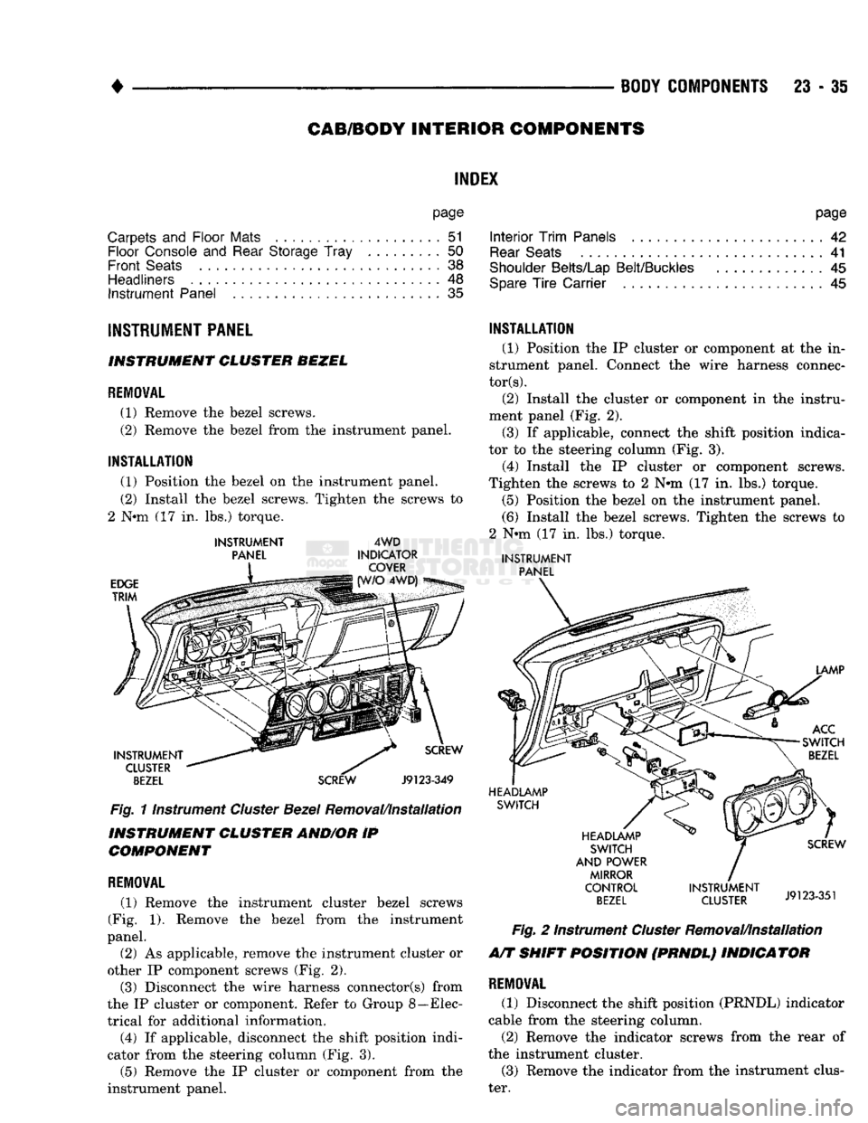
(1) Remove
the
bezel screws.
(2) Remove
the
bezel from
the
instrument panel.
INSTALLATION
(1) Position
the
bezel
on the
instrument panel.
(2) Install
the
bezel screws. Tighten
the
screws
to
2
Nnn (17 in. lbs.)
torque.
INSTRUMENT
PANEL
EDGE
TRIM
4WD
INDICATOR COVER 4WD)
INSTRUMENT CLUSTER
BEZEL
SCREW
Fig.
11nstrument
Cluster
Bezel
Removal/Installation
INSTRUMENT CLUSTER AND/OR
IP
COMPONENT
REMOVAL
(1) Remove
the
instrument cluster bezel screws
(Fig.
1).
Remove
the
bezel from
the
instrument
panel.
(2)
As
applicable, remove
the
instrument cluster
or
other
IP
component screws
(Fig. 2).
(3) Disconnect
the
wire harness connector(s) from
the
IP
cluster
or
component. Refer
to
Group 8—Elec
trical
for
additional information. (4)
If
applicable, disconnect
the
shift position indi
cator from
the
steering column
(Fig. 3).
(5) Remove
the IP
cluster
or
component from
the
instrument panel.
INSTALLATION
(1) Position
the IP
cluster
or
component
at the in
strument panel. Connect
the
wire harness connec
tors).
(2) Install
the
cluster
or
component
in the
instru
ment panel
(Fig. 2).
(3)
If
applicable, connect
the
shift position indica
tor
to the
steering column
(Fig. 3).
(4) Install
the IP
cluster
or
component screws.
Tighten
the
screws
to 2 N#m (17 in. lbs.)
torque. (5) Position
the
bezel
on the
instrument panel.
(6) Install
the
bezel screws. Tighten
the
screws
to
2
Nnn (17 in. lbs.)
torque.
INSTRUMENT
PANEL
LAMP
ACC
SWITCH
BEZEL
HEADLAMP SWITCH
HEADLAMP SWITCH
AND POWER MIRROR
CONTROL
BEZEL
SCREW
INSTRUMENT
J9123351
CLUSTER
J9123-351
Fig.
2
Instrument
Cluster
Removal/Installation
A/T SHIFT POSITION (PRNDL) INDICATOR
REMOVAL
(1) Disconnect
the
shift position (PRNDL) indicator
cable from
the
steering column.
(2) Remove
the
indicator screws from
the
rear
of
the instrument cluster. (3) Remove
the
indicator from
the
instrument clus
ter.
Page 1421 of 1502
23 - 38
BODY COMPONENTS
— —
^—_____— —
•
PAWU
NUT
WASHER
SEALS
DASH
PANEL
SEAL
SUPPORT
BRACKET
NUT
INSTRUMENT
PANEL
RELEASE
HANDLE SCREW
RETAINER'
PARKING
BRAKE
SCREW LEVER J9123-568
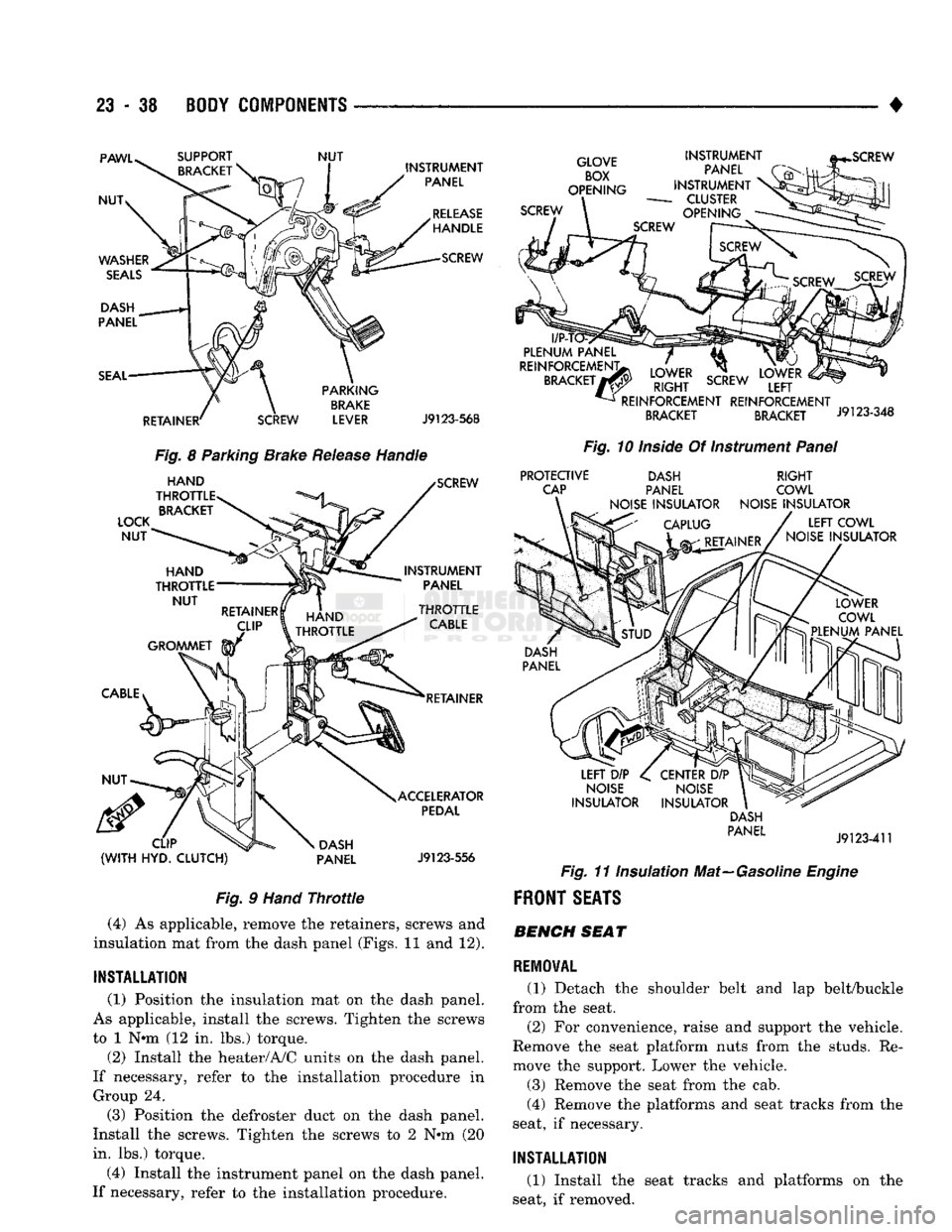
Fig.
8 Parking Brake
Release
Handle
LOCK
NUT
HAND
THROTTLE BRACKET SCREW
INSTRUMENT PANEL
HAND
^TfJlLE
>TTLE
RETAINER
CLIP
(WITH
HYD.
CLUTCH)
DASH
PANEL ACCELERATOR
PEDAL
J9123-556
Fig.
9
Hand
Throttle
(4) As applicable, remove the retainers, screws and
insulation mat from the dash panel (Figs. 11 and 12).
INSTALLATION
(1) Position the insulation mat on the dash panel.
As applicable, install the screws. Tighten the screws
to 1 N«m (12 in. lbs.) torque.
(2) Install the heater/A/C units on the dash panel.
If necessary, refer to the installation procedure in Group 24.
(3) Position the defroster duct on the dash panel.
Install the screws. Tighten the screws to 2 N*m (20
in. lbs.) torque.
(4) Install the instrument panel on the dash panel.
If necessary, refer to the installation procedure.
GLOVE
BOX
OPENING
SCREW INSTRUMENT
PANEL
INSTRUMENT
-
CLUSTER
OPENING
l/P-T
PLENUM
PANEL
REINFORCEMENT;
BRACKET
7
LOWER
RIGHT
SCREW
REINFORCEMENT REINFORCEMENT
BRACKET BRACKET J9123-348
Fig.
10
Inside
Of Instrument
Panel
PROTECTIVE
CAP DASH
PANEL
NOISE
INSULATOR
RIGHT
COWL
NOISE
INSULATOR
LEFT
COWL
NOISE
INSULATOR
LEFT
DIP
NOISE
INSULATOR
CENTER
DIP
NOISE
INSULATOR DASH
PANEL
J9123-411
Fig.
11 Insulation Mat—Gasoline
Engine
FRONT
SEATS BENCH SEAT
REMOVAL
(1) Detach the shoulder belt and lap belt/buckle
from the seat.
(2) For convenience, raise and support the vehicle.
Remove the seat platform nuts from the studs. Re
move the support. Lower the vehicle.
(3) Remove the seat from the cab.
(4) Remove the platforms and seat tracks from the
seat, if necessary.
INSTALLATION
(1) Install the seat tracks and platforms on the
seat, if removed.
Page 1422 of 1502
•
BODY
COMPONENTS
23 - 39
Fig.
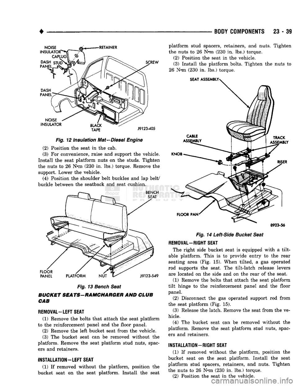
12 Insulation Mat—Diesel
Engine
(2) Position the seat in the cab.
(3) For convenience, raise and support the vehicle.
Install the seat platform nuts on the studs. Tighten
the nuts to 26 Nnn (230 in. lbs.) torque. Remove the support. Lower the vehicle.
(4) Position the shoulder belt buckles and lap belt/
buckle between the seatback and seat cushion.
Fig.
13
Bench
Seat
BUCKET SEATS-RAMCHARGER AND CLUB CAB
REMOVAL—LEFT SEAT
(1) Remove the bolts that attach the seat platform
to the reinforcement panel and the floor panel.
(2) Remove the left bucket seat from the vehicle.
(3) The bucket seat can be removed without the
platform. Remove the seat platform stud nuts, spac ers and retainers. platform stud spacers, retainers, and nuts. Tighten
the nuts to 26 Nnn (230 in. lbs.) torque.
(2) Position the seat in the vehicle. (3) Install the platform bolts. Tighten the nuts to
26 Nnn (230 in. lbs.) torque.
8923-56
Fig.
14
Left-Side
Bucket Seat
REMOVAL—RIGHT SEAT
The right side bucket seat is equipped with a tilt-
able platform. This is to provide entry to the rear
seating area (Fig. 15). When tilted, a gas operated
rod supports the seat. The tilt-latch release levers are located on the side and on the rear of the seat.
(1) Remove the bolts that attach the seat platform
tilt hinge to the reinforcement panel and the floor
panel.
(2) Disconnect the gas operated support rod from
the seat platform (Fig. 15).
(3) Release the latch. Remove the seat from the ve
hicle.
(4) The bucket seat can be removed without the
platform. Remove the seat platform stud nuts, spac ers and retainers.
INSTALLATION-RIGHT
SEAT
(1) If removed without the platform, position the
bucket seat on the seat platform. Install the seat
platform stud spacers, retainers, and nuts. Tighten
the nuts to 26 Nnn (230 in. lbs.) torque.
(2) Position the seat in the vehicle.
INSTALLATION—LEFT
SEAT
(1) If removed without the platform, position the
bucket seat on the seat platform. Install the seat
Page 1424 of 1502
•
BODY COMPONENTS
23 - 41
RELEASE
SCREW TRACK
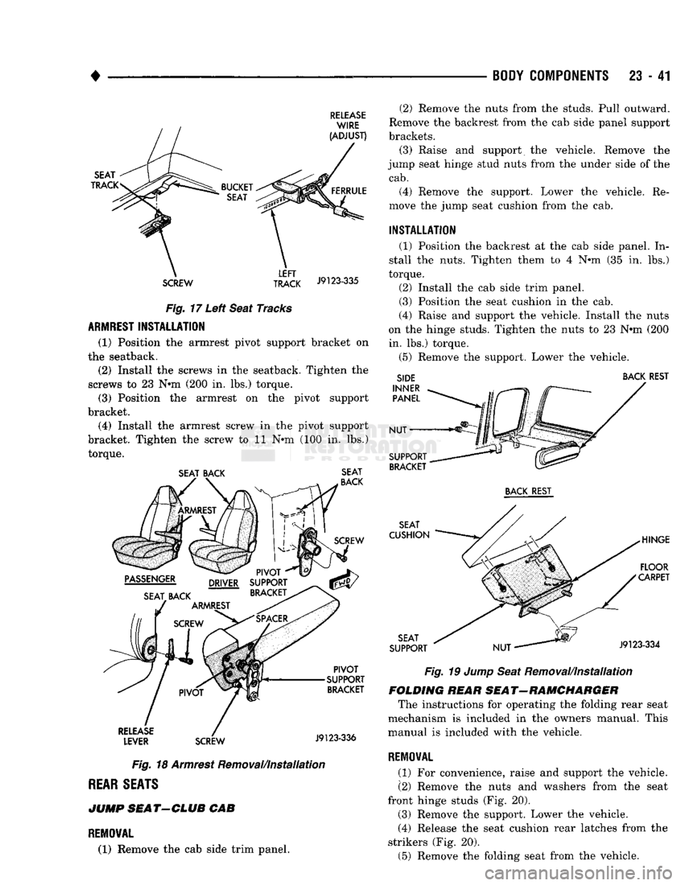
J9123"335 Fig. 17 Left Seat Tracks
ARMREST
INSTALLATION
(1) Position the armrest pivot support bracket on
the seatback.
(2) Install the screws in the seatback. Tighten the
screws to 23 N*m (200 in. lbs.) torque. (3) Position the armrest on the pivot support
bracket.
(4) Install the armrest screw in the pivot support
bracket. Tighten the screw to 11 N*m (100 in. lbs.) torque.
SEAT BACK SEAT
Fig. 18 Armrest Removal/Installation
REAR
SEATS
JUMP
SEAT-CLUB
CAB
REMOVAL
(1) Remove the cab side trim panel. (2) Remove the nuts from the studs. Pull outward.
Remove the backrest from the cab side panel support
brackets.
(3) Raise and support the vehicle. Remove the
jump seat hinge stud nuts from the under side of the
cab.
(4) Remove the support. Lower the vehicle. Re
move the jump seat cushion from the cab.
INSTALLATION
(1) Position the backrest at the cab side panel. In
stall the nuts. Tighten them to 4 N*m (35 in. lbs.)
torque.
(2) Install the cab side trim panel.
(3) Position the seat cushion in the cab.
(4) Raise and support the vehicle. Install the nuts
on the hinge studs. Tighten the nuts to 23 N#m (200 in. lbs.) torque.
(5) Remove the support. Lower the vehicle.
SIDE BACK REST
Fig. 19 Jump Seat Removal/installation
FOLDING HEAR SEAT-RAMCHARGER The instructions for operating the folding rear seat
mechanism is included in the owners manual. This
manual is included with the vehicle.
REMOVAL
(1) For convenience, raise and support the vehicle.
(2) Remove the nuts and washers from the seat
front hinge studs (Fig. 20).
(3) Remove the support. Lower the vehicle.
(4) Release the seat cushion rear latches from the
strikers (Fig. 20).
(5) Remove the folding seat from the vehicle.
Page 1429 of 1502
23
- 46
BODY
COMPONENTS
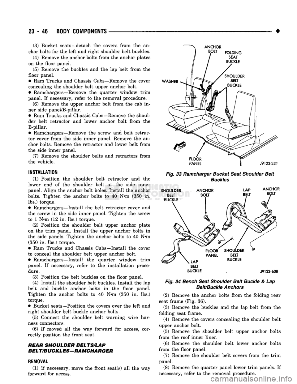
• (3) Bucket seats—detach the covers from the an
chor bolts for the left and right shoulder belt buckles.
(4) Remove the anchor bolts from the anchor plates
on the floor panel.
(5)
Remove the buckles and the lap belt from the
floor panel.
• Ram Trucks and Chassis Cabs—Remove the cover
concealing the shoulder belt upper anchor bolt.
• Ramchargers—Remove the quarter window trim
panel. If necessary, refer to the removal procedure.
(6) Remove the upper anchor bolt from the cab in
ner side panel/B-pillar.
• Ram Trucks and Chassis Cabs—Remove the shoul
der belt retractor and lower anchor bolt from the B-pillar.
• Ramchargers—Remove the screw and belt retrac
tor cover from the side inner panel. Remove the an chor bolts. Remove the retractor and lower belt from
the side inner panel.
(7) Remove the shoulder belts and retractors from
the vehicle.
INSTALLATION
(1) Position the shoulder belt retractor and the
lower end of the shoulder belt at the side inner
panel. Align the anchor bolt holes. Install the anchor
bolts.
Tighten the anchor bolts to 40 N*m (350 in. lbs.) torque.
• Ramchargers—Install the belt retractor cover and
the screw in the side inner panel. Tighten the screw
to 1 N»m (12 in. lbs.) torque.
(2) Position the shoulder belt upper anchor plate
on the trim panel. Install the upper anchor bolts in
the side panels. Tighten the anchor bolts to 40 N#m (350 in. lbs.) torque.
• Ram Trucks and Chassis Cabs—Install the cover
to conceal the shoulder belt upper anchor bolt.
• Ramchargers—Install the quarter window trim
panel. If necessary, refer to the installation proce
dure.
(3) Position the belt buckles on the floor panel.
(4) Install the shoulder belt buckles. Install the lap
belt and buckle anchor bolts in the floor panel.
Tighten the anchor bolts to 40 N«m (350 in. lbs.) torque.
• Bucket seats—Position the covers over the left and
right shoulder belt buckle anchor bolts.
(5) Connect the shoulder belt warning wire har
ness connectors. (6) If moved all the way forward for access, cor
rectly position the front seat.
REAR
SHOULDER
BELTS/LAP
BELT/BUCKLES-RAMCHARGER
REMOVAL
(1) If necessary, move the front seat(s) all the way
forward for access.
Fig.
33
Ramcharger
Bucket
Seat
Shoulder
Belt
Buckles
SHOULDER
ANCHOR
LAP
BELT
BUCKLE
.
J9123-608
Fig.
34
Bench
Seat
Shoulder
Belt
Buckle
& Lap
Belt/Buckle
Anchors
(2) Remove the anchor bolts from the folding rear
seat frame (Fig. 36). (3) Remove the buckles and the lap belt from the
folding seat frame. (4) Remove the covers concealing the shoulder belt
upper anchor bolt.
(5) Remove the shoulder belt upper anchor bolts
from the roof inner liner.
(6) Remove the shoulder belt lower anchor bolts
from the floor panel.
(7) Remove the shoulder belt covers from the trim
panel.
(8) Remove the quarter panel lower trim panels. If
necessary, refer to the removal procedure.
Page 1444 of 1502
•
HEATING AND AIR CONDITIONING 24 - 7 AIR CONDITIONING SYSTEM
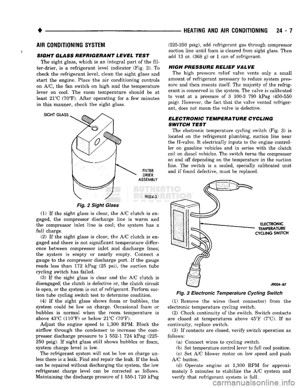
SIGHT GLASS REFRIGERANT LEWEL TEST The sight glass, which is an integral part of the fil
ter-drier, is a refrigerant level indicator (Fig. 2). To check the refrigerant level, clean the sight glass and
start the engine. Place the air conditioning controls
on A/C, the fan switch on high and the temperature lever on cool. The room temperature should be at
least 21°C (70°F). After operating for a few minutes
in this manner, check the sight glass.
SIGHT
GLASS
FILTER
DRIER
ASSEMBLY
9024-3
Fig.
2 Sight Glass
(1) If the sight glass is clear, the A/C clutch is en
gaged, the compressor discharge line is warm and
the compressor inlet line is cool; the system has a
full charge.
(2) If the sight glass is clear, the A/C clutch is en
gaged and there is not significant temperature differ
ence between compressor inlet and discharge lines;
the system is empty or nearly empty. Connect a gauge to the compressor discharge port. If the gauge
reads less than 172 kPag (25 psi), the suction tube cycling switch has failed.
(3) If the sight glass is clear and the A/C clutch is
disengaged; the clutch is defective or, the clutch circuit
is open, or the system is out of refrigerant. Perform suc
tion tube cycling switch test to determine condition.
(4) If the sight glass shows foam or bubbles, the
system could be low on charge. Occasional foam or
bubbles is normal when the room temperature is above 43°C (110°F) or below 21°C (70°F).
Adjust the engine speed to 1,300 RPM. Block the
airflow through the condenser to increase the com
pressor discharge pressure to 1 552-1 724 kPag (225- 250 psig). If sight glass still shows bubbles or foam,
system charge level is low. The refrigerant system will not be low on charge un
less there is a leak. Find and repair the leak. If the leak
can be repaired without discharging the system, the low
refrigerant charge level can be corrected as follows.
Maintaining the discharge pressure of 1 550-1 720 kPag (225-250 psig), add refrigerant gas through compressor
suction line until foam is cleared from sight glass. Then
add 13 oz. (368 g) or 1 can of refrigerant.
HIGH PRESSURE RELIEF
WALWE
The high pressure relief valve vents only a small
amount of refrigerant necessary to reduce system pres
sure and then reseats
itself.
The majority of the refrig
erant is conserved in the system. The valve is calibrated
to vent at a pressure of 3 100-3 790 kPag (450-550
psig).
However, the fact that the valve vented refriger ant, does not mean the valve is defective.
ELECTRONIC TEMPERATURE CYCLING
SWITCH TEST The electronic temperature cycling switch (Fig. 3) is
located on the refrigerant plumbing, suction line near
the H-valve. It electrically inputs to the engine control ler on gasoline vehicles and in series with the clutch
coil on diesel vehicles. The switch turns the compressor
on and off depending on the temperature in the suction
line.
The switch is a sealed, specially calibrated unit and if found defective, must be replaced.
ELECTRONIC
TEMPERATURE
CYCLING
SWITCH
J9324-97
Fig.
3 Electronic
Temperature
Cycling
Switch
(1) Remove the wires (boot connector) from the
electronic temperature cycling switch. (2) Check continuity of the switch. Switch contacts
are closed at temperatures above 45°F (7°C). If no
continuity, replace switch.
(3) If contacts are closed, verify switch operation as
follows:
(a) Connect wires to cycling switch.
(b) Set temperature control lever to full cool position. (c) Set A/C blower motor on low speed and push
A/C button.
(d) Operate engine at 1,300 RPM for approxi
mately 5 minutes to stabilize the A/C system and
verify that refrigerant system is full.