1993 DODGE TRUCK relay
[x] Cancel search: relayPage 345 of 1502
8B
- 4
BATTERY/STARTER/GENERATOR SERVICE
•
STARTER SERVICE PROCEDURES
GENERAL INFORMATION
This section will cover the Starter removal and in
stallation. For diagnostic procedures, see Group 8A -
Battery/Starting/Charging Systems Diagnostics.
STARTING
SYSTEM DESCRIPTION
The starter system circuits consist of:
• a battery
• engine starter motor and solenoid
• starter relay
• ignition switch
© park/neutral position switch (automatic transmis sion)
• clutch interlock switch (manual transmission-die-
sel)
• connecting wires and battery cables. Turning the ignition switch to the start position,
causes the starter relay points to close allowing cur
rent to energize solenoid windings. This causes sole
noid plunger and clutch shift lever to move engaging
clutch pinion gear into ring gear. At the same time
the solenoid contacts close causing starter motor to
crank. As soon as engine starts running clutch pin ion gear overruns to protect starter armature from
damage due to excessive speed. Once the engine starts running, the ignition key switch should be im
mediately returned to the run position to prevent ex
cessive starter motor damage.
WARNING:
ALWAYS DISCONNECT NEGATIVE
CA
BLE FROM
BATTERY
BEFORE SERVICING
THE
STARTER.
STARTER
MOTOR REMOVAL AND INSTALLATION EXCEPT DIESEL
(1) Disconnect negative cable from battery.
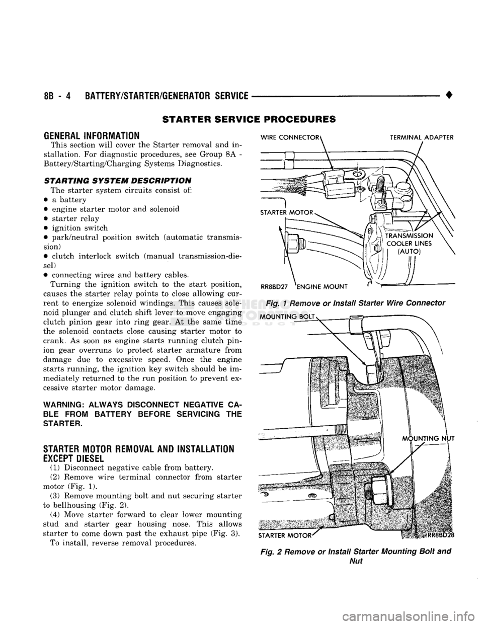
(2) Remove wire terminal connector from starter
motor (Fig. 1). (3) Remove mounting bolt and nut securing starter
to bellhousing (Fig. 2).
(.4) Move starter forward to clear lower mounting
stud and starter gear housing nose. This allows
starter to come down past the exhaust pipe (Fig. 3). To install, reverse removal procedures.
Fig.
2
Remove
or Install
Starter
Mounting
Bolt
and
Nut
Page 352 of 1502
•
IGNITION
SYSTEMS
8D
- 1
CONTENTS
page page
COMPONENT IDENTIFICATION/SYSTEM DIAGNOSTICS/SERVICE PROCEDURES
7
OPERATION
1
IGNITION SWITCH
25
COMPONENT REMOVAL/INSTALLATION
..... 18
SPECIFICATIONS
28
COMPONENT
IDENTIFICATION/SYSTEM OPERATION
INDEX
page
Automatic
Shut Down (ASD) Relay
1
Camshaft Position Sensor
2
Crankshaft Position Sensor
2
Distributors
3
Engine Coolant
Temperature
Sensor
...........
4
General
Information
1
page
Ignition
Coil
3
Intake
Manifold Charge
Air
Temperature
Sensor
. . 4
Manifold Absolute Pressure (MAP) Sensor
4
Powertrain
Control
Module (PCM)
. 5
Throttle
Position Sensor
5
GENERAL
INFORMATION
Throughout this group, references
are
made
to
par
ticular vehicle models
by
alphabetical designation
or
by
the
particular vehicle nameplate.
A
chart showing a breakdown
of
alphabetical designations
is
included
in
the
Introduction group
at the
beginning
of
this
manual. 5.9L
gas
powered engines will
be
referred
to as ei
ther: LDC (Light Duty Cycle),
or
HDC (Heavy Duty Cycle). This section
of the
group, Component Identifica
tion/System Operation, will discuss ignition system operation
and
will identify ignition system compo
nents.
For diagnostic procedures
and
adjustments, refer
to
the Diagnostics/Service Procedures section
of
this
group.
For removal
and
installation
of
ignition system
components, refer
to the
Component Removal/Instal
lation section
of
this group. For other useful information, refer
to
On-Board
Di
agnostics
in the
General Diagnosis sections
of
Group
14,
Fuel System
in
this manual. For operation
of the DRB II
Diagnostic Scan Tool,
refer
to the
appropriate Powertrain Diagnostic Proce
dures service manual.
An Ignition specifications section
is
included
at the
end
of
this group.
A
general Maintenance Schedule (mileage intervals)
for
ignition related items
can be
found
in
Group
0,
Lubrication and Maintenance. This
schedule
can
also
be
found
in the
Owners Manual.
IGNITION
SYSTEMS
The ignition systems used
on all
engines
are
basi
cally identical. Similarities
and
differences between
the systems will
be
discussed.
A sequential multi-port fuel injection system
is
used
on all gas
powered engines.
The ignition system
is
controlled
by the
powertrain
control module (PCM)
on all
engines.
The
PCM
was
formerly referred
to as the
SBEC
or
engine control ler.
The ignition system consists
of:
• Spark Plugs
• Ignition Coil
• Secondary Ignition Cables
• Ignition distributor. Contains rotor
and
camshaft
position sensor • Powertrain Control Module (PCM)
• Crankshaft Position Sensor
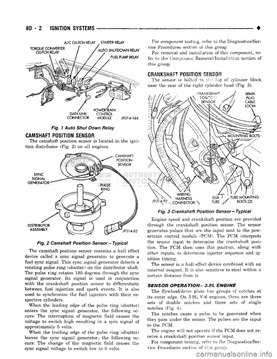
AUTOMATIC SHUT DOWN (ASD) RELAY
The automatic shut down (ASD) relay
is
located
in
the engine compartment (Fig.
1). As one of its
func
tions,
the ASD
relay will supply battery voltage
to
the ignition coil.
The
ground circuit
for the
ASD
re
lay
is
controlled
by the
powertrain control module (PCM).
The PCM
regulates
ASD
relay operation
by
switching
the
ground circuit on-and-off.
IGNITION
SYSTEMS
Page 353 of 1502
8D
- 2
IGNITION
SYSTEMS
•
A/C
CLUTCH RELAY STARTER RELAY
DATA LINK CONTROL
CONNECTOR
MODULE J9314-164
Fig.
1
Auto
Shut Down
Relay
CAMSHAFT POSITION SENSOR
The camshaft position sensor is located in the igni
tion distributor (Fig. 2) on all engines.
Fig.
2 Camshaft Position
Sensor—
Typical
The camshaft position sensor contains a hall effect
device called a sync signal generator to generate a
fuel sync signal. This sync signal generator detects a
rotating pulse ring (shutter) on the distributor shaft.
The pulse ring rotates 180 degrees through the sync signal generator. Its signal is used in conjunction
with the crankshaft position sensor to differentiate
between fuel injection and spark events. It is also
used to synchronize the fuel injectors with their re spective cylinders.
When the leading edge of the pulse ring (shutter)
enters the sync signal generator, the following oc
curs:
The interruption of magnetic field causes the
voltage to switch high resulting in a sync signal of approximately 5 volts.
When the trailing edge of the pulse ring (shutter)
leaves the sync signal generator, the following oc
curs:
The change of the magnetic field causes the sync signal voltage to switch low to 0 volts. For component testing, refer to the Diagnostics/Ser
vice Procedures section of this group. For removal and installation of this component, re
fer to the Component Removal/Installation section of this group.
CRANKSHAFT
POSITION
SENSOR
The sensor is bolted to the top of cylinder block
near the rear of the right cylinder head (Fig. 3).
Fig.
3 Crankshaft Position Sensor—Typical
*
Engine speed and crankshaft position are provided
through the crankshaft position sensor. The sensor generates pulses that are the input sent to the pow
ertrain control module (PCM). The PCM interprets
the sensor input to determine the crankshaft posi
tion. The PCM then uses this position, along with other inputs, to determine injector sequence and ig
nition timing.
The sensor is a hall effect device combined with an
internal magnet. It is also sensitive to steel within a
certain distance from it.
SENSOR
OPERATION-3.9L
ENGINE
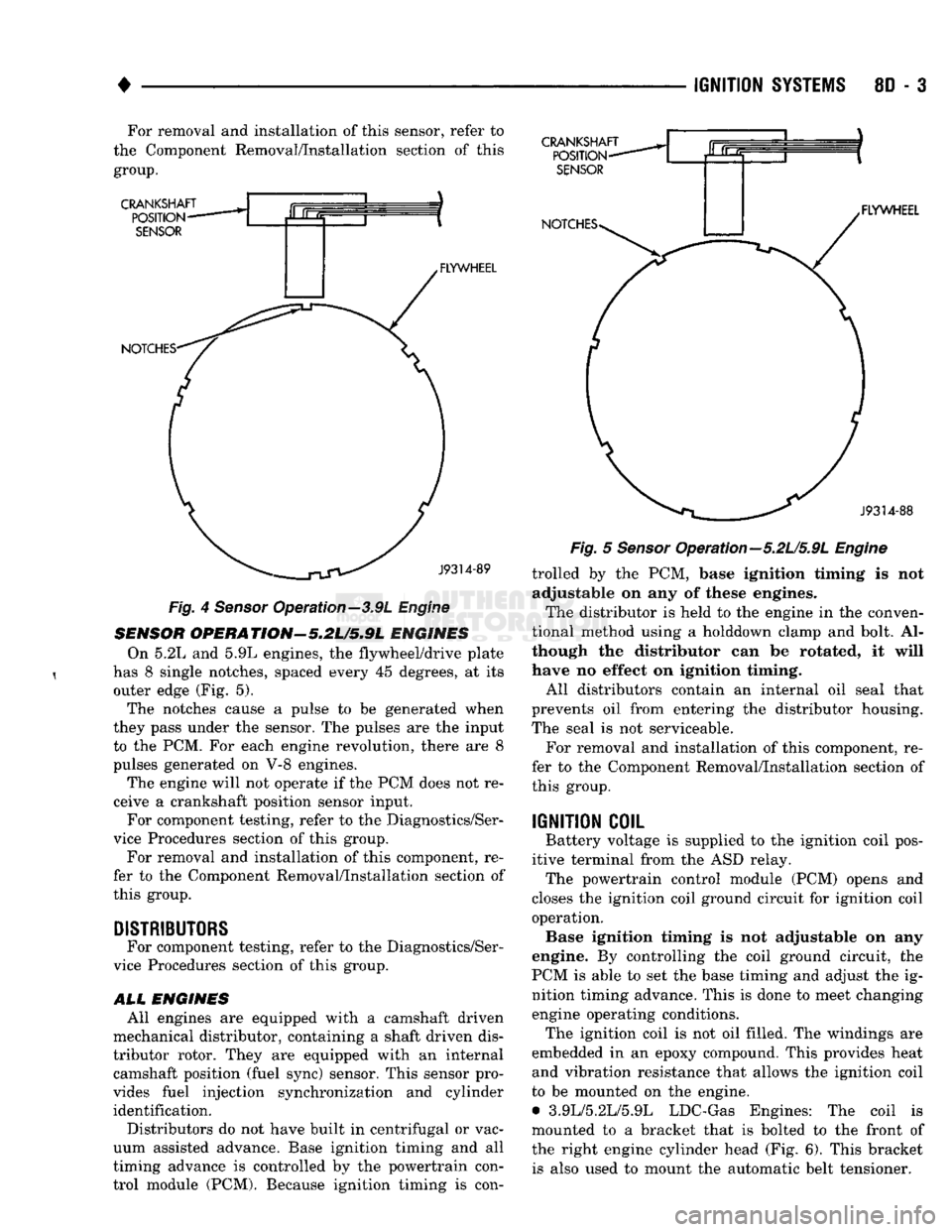
The flywheel/drive plate has groups of notches at
its outer edge. On 3.9L V-6 engines, there are three sets of double notches and three sets of single
notches (Fig.
4).
The notches cause a pulse to be generated when
they pass under the sensor. The pulses are the input to the PCM.
The engine will not operate if the PCM does not re
ceive a crankshaft position sensor input.
For component testing, refer to the Diagnostics/Ser
vice Procedures section of this group.
Page 354 of 1502
•
IGNITION
SYSTEMS
8D - 3 For removal and installation of this sensor, refer to
the Component Removal/Installation section of this
group.
CRANKSHAFT
POSITION
SENSOR
NOTCHES- FLYWHEEL CRANKSHAFT
POSITION-
SENSOR
NOTCHES* .FLYWHEEL
J9314-88
—^^j^jV^
J9314-89
Fig.
4
Sensor
Operation—3.9L
Engine
SENSOR
OPERATION'-5.2U5.9L
ENGINES On 5.2L and 5.9L engines, the flywheel/drive plate
has 8 single notches, spaced every 45 degrees, at its outer edge (Fig. 5).
The notches cause a pulse to be generated when
they pass under the sensor. The pulses are the input to the PCM. For each engine revolution, there are 8
pulses generated on V-8 engines.
The engine will not operate if the PCM does not re
ceive a crankshaft position sensor input. For component testing, refer to the Diagnostics/Ser
vice Procedures section of this group.
For removal and installation of this component, re
fer to the Component Removal/Installation section of
this group.
DISTRIBUTORS
For component testing, refer to the Diagnostics/Ser
vice Procedures section of this group.
ALL
ENGINES All engines are equipped with a camshaft driven
mechanical distributor, containing a shaft driven dis
tributor rotor. They are equipped with an internal camshaft position (fuel sync) sensor. This sensor pro
vides fuel injection synchronization and cylinder identification.
Distributors do not have built in centrifugal or vac
uum assisted advance. Base ignition timing and all
timing advance is controlled by the powertrain con
trol module (PCM). Because ignition timing is con-
Fig.
5
Sensor
Opera tion—5.2L/5.9L
Engine
trolled by the PCM, base ignition timing is not adjustable on any of these engines.
The distributor is held to the engine in the conven
tional method using a holddown clamp and bolt. Al
though the distributor can be rotated, it will
have no effect on ignition timing.
All distributors contain an internal oil seal that
prevents oil from entering the distributor housing.
The seal is not serviceable.
For removal and installation of this component, re
fer to the Component Removal/Installation section of
this group.
IGNITION
COIL
Battery voltage is supplied to the ignition coil pos
itive terminal from the ASD relay. The powertrain control module (PCM) opens and
closes the ignition coil ground circuit for ignition coil operation. Base ignition timing is not adjustable on any
engine. By controlling the coil ground circuit, the
PCM is able to set the base timing and adjust the ig nition timing advance. This is done to meet changing engine operating conditions. The ignition coil is not oil filled. The windings are
embedded in an epoxy compound. This provides heat and vibration resistance that allows the ignition coil
to be mounted on the engine. • 3.9L/5.2L/5.9L LDC-Gas Engines: The coil is
mounted to a bracket that is bolted to the front of the right engine cylinder head (Fig. 6). This bracket is also used to mount the automatic belt tensioner.
Page 356 of 1502
•
IGNITION
SYSTEMS
8D - 5
THROTTLE
^
BODY
u
BRACKET
y^SUPPORT
BRACKET
/ |
CHARGE
AIR
ijmmmmk
TEMPERATURE
SENSOR
THROTTLE
BODY
Fig.
9
Sensor
Location—3.9L Engine—Typical
INTAKE MANIFOLD
'b AIR TEMPERATURE
SENSOR
J9314-162
Fig.
10
Sensor
Location—5.2L/5.9L
Engines—Typical
start-up (cranking) and to engine load while the en
gine is running. The PCM uses this input, along with
inputs from other sensors, to adjust air-fuel mixture.
For more information, refer to Group 14, Fuel Sys
tem.
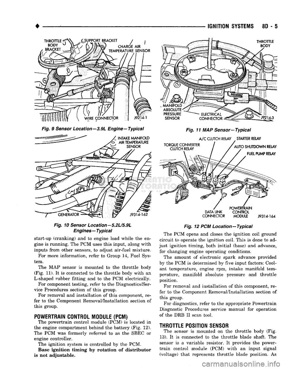
The MAP sensor is mounted to the throttle body
(Fig. 11). It is connected to the throttle body with an
L-shaped rubber fitting and to the PCM electrically. For component testing, refer to the Diagnostics/Ser
vice Procedures section of this group. For removal and installation of this component, re
fer to the Component Removal/Installation section of
this group.
POWERTRAIN CONTROL MODULE
(PCM) The powertrain control module (PCM) is located in
the engine compartment behind the battery (Fig. 12).
The PCM was formerly referred to as the SBEC or engine controller. The ignition system is controlled by the PCM. Base ignition timing by rotation of distributor
is not adjustable.
MANIFOLD
ABSOLUTE
PRESSURE
SENSOR
TORQUE CONVERTER CLUTCH RELAY
ELECTRICAL
Jlp^
CONNECTOR
^gis!—
Fig.
11 MAP Sensor—Typical
A/C
CLUTCH RELAY STARTER RELAY
AUTO
SHUTDOWN RELAY FUEL PUMP RELAY
DATA LINK
CONNECTOR POWERTRAIN
CONTROL
MODULE
J9314-164
Fig.
12 PCM Location—Typical The PCM opens and closes the ignition coil ground
circuit to operate the ignition coil. This is done to ad
just ignition timing, both initial (base) and advance, for changing engine operating conditions.
The amount of electronic spark advance provided
by the PCM is determined by five input factors: Cool ant temperature, engine rpm, intake manifold tem
perature, manifold absolute pressure and throttle
position.
For removal and installation of this component, re
fer to the Component Removal/Installation section of
this group.
For diagnostics, refer to the appropriate Powertrain
Diagnostic Procedures service manual for operation
of the DRB II scan tool.
THROTTLE
POSITION
SENSOR
The sensor is mounted on the throttle body (Fig.
13).
It is connected to the throttle blade shaft. The
sensor is a variable resistor. It provides the power-
train control module (PCM) with an input signal (voltage) that represents throttle blade position. As
Page 358 of 1502
•
IGNITION
SYSTEMS
80 - 7
DIAGNOSTICS/SERW1CE
PROCEDURES
INDEX
page
Automatic Shut Down (ASD) Relay
7
Camshaft Position
Sensor
Test
...............
7
Crankshaft Position
Sensor
Test
8
Distributor
Cap
8
Distributor
Rotor
8
Engine
Coolant Temperature
Sensor
Test
10
General
Information
7
Ignition
Coil
8
Ignition
Secondary
Circuit
Diagnosis
10
GENERAL
INFORMATION
This section
of the
group, Diagnostics/Service Pro
cedures, will discuss basic ignition system diagnos
tics
and
service adjustments. For system operation
and
component identification,
refer
to the
Component Identification/System Opera
tion section
of
this group. For removal
or
installation
of
ignition system com
ponents, refer
to the
Component Removal/Installa
tion section
of
this group. For other useful information, refer
to
On-Board
Di
agnostics
in the
General Diagnosis sections
of
Group
14,
Fuel System
in
this manual. For operation
of the DRB II
Diagnostic Scan Tool,
refer
to the
appropriate Powertrain Diagnostic Proce
dures service manual.
AUTOMATIC SHUT DOWN
(ASD)
RELAY
Refer
to
Relays—Operation/Testing
in the
Group
14,
Fuel System section
of
this service manual.
CAMSHAFT POSITION SENSOR TEST
The camshaft position sensor
is
located
in the
dis
tributor
on all
engines. To perform
a
complete test
of
this sensor
and its
circuitry, refer
to the DRB II
diagnostic scan tool.
Also refer
to the
appropriate Powertrain Diagnostics
Procedures manual.
To
test
the
sensor only, refer
to
the following: For this test,
an
analog (non-digital) voltmeter
is needed.
Do not
remove
the
distributor connector from
the
distributor. Using small paper clips, insert
them into
the
backside
of the
distributor wire har ness connector
to
make contact with
the
terminals.
Be sure that
the
connector
is not
damaged when
in
serting
the
paper clips. Attach voltmeter leads
to
these paper clips. (1) Connect
the
positive (
+
)
voltmeter lead into
the sensor output wire. This
is at
done
the
distribu tor wire harness connector.
For
wire identification,
refer
to
Group
8W,
Wiring Diagrams.
page
Ignition
Timing
12
Intake Manifold Charge
Air
Temperature
Sensor
Test
12
Manifold Absolute Pressure (MAP)
Sensor
Test
. 12
Oxygen
Sensor
Tests
17
Powertrain Control Module (PCM)
............
14
Spark
Plug Secondary Cables
16
Spark
Plugs
............................
14
Throttle
Position
Sensor
Test
17
(2) Connect
the
negative
(-)
voltmeter lead into
the
ground wire.
For
wire identification, refer
to
Group
8W, Wiring Diagrams.
(3)
Set the
voltmeter
to the 15
Volt
DC
scale. (4) Remove distributor
cap
from distributor
(two
screws). Rotate (crank)
the
engine until
the
distribu
tor rotor
is
pointed towards
the
rear
of
vehicle.
The
movable pulse ring should
now be
within
the
sensor
pickup.
(5) Turn ignition
key to ON
position. Voltmeter
should read approximately
5.0
volts.
(6)
If
voltage
is not
present, check
the
voltmeter
leads
for a
good connection.
(7)
If
voltage
is
still
not
present, check
for
voltage
at
the
supply wire.
For
wire identification, refer
to
Group
8W,
Wiring Diagrams.
(8)
If
voltage
is not
present
at
supply wire, check
for voltage
at
pin-7
of
powertrain control module (PCM) 60-way connector. Leave
the PCM
connector
connected
for
this test. (9)
If
voltage
is
still
not
present, perform vehicle
test using
the DRB II
diagnostic scan tool. (10)
If
voltage
is
present
at
pin-7,
but not at the
supply wire: (a) Check continuity between
the
supply wire.
This
is
checked between
the
distributor connector and pin-7
at the PCM. If
continuity
is not
present,
repair
the
harness
as
necessary. (b) Check
for
continuity between
the
camshaft
position sensor output wire
and
pin-44
at the PCM.
If continuity
is not
present, repair
the
harness
as
necessary. (c) Check
for
continuity between
the
ground cir
cuit wire
at the
distributor connector
and
ground.
If continuity
is not
present, repair
the
harness
as
necessary. (11) While observing
the
voltmeter, crank
the en
gine with ignition switch.
The
voltmeter needle should fluctuate between
0 and 5
volts while
the en
gine
is
cranking. This verifies that
the
camshaft
po
sition sensor
in the
distributor
is
operating properly
and
a
sync pulse signal
is
being generated.
Page 362 of 1502
*
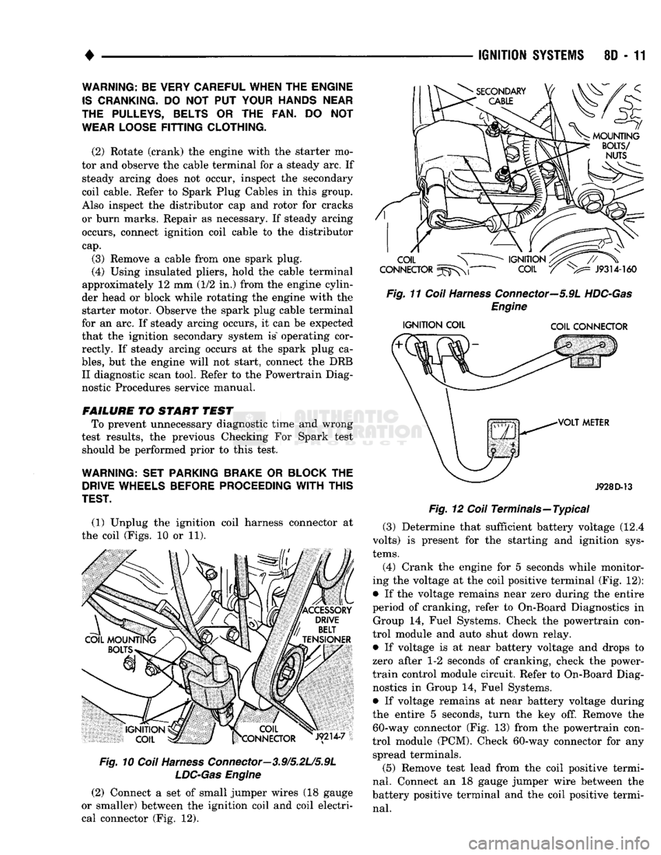
(1) Unplug the ignition coil harness connector at
the coil (Figs. 10 or 11).
Fig.
10
Coil
Harness
Connector—3.9/5.2L/5.9L
LDC-Gas
Engine
(2) Connect a set of small jumper wires (18 gauge
or smaller) between the ignition coil and coil electri
cal connector (Fig. 12).
IGNITION
SYSTEMS
80 - 11
Fig.
11
Coil
Harness
Connector—5.9L
HDC-Gas
Engine
IGNITION
COIL COIL CONNECTOR
J928D-13
Fig.
12
Coil
Terminals—Typical (3) Determine that sufficient battery voltage (12.4
volts) is present for the starting and ignition sys
tems.
(4) Crank the engine for 5 seconds while monitor
ing the voltage at the coil positive terminal (Fig. 12):
• If the voltage remains near zero during the entire
period of cranking, refer to On-Board Diagnostics in Group 14, Fuel Systems. Check the powertrain con
trol module and auto shut down relay.
• If voltage is at near battery voltage and drops to
zero after 1-2 seconds of cranking, check the power-
train control module circuit. Refer to On-Board Diag nostics in Group 14, Fuel Systems.
• If voltage remains at near battery voltage during
the entire 5 seconds, turn the key off. Remove the 60-way connector (Fig. 13) from the powertrain con
trol module (PCM). Check 60-way connector for any spread terminals.
(5) Remove test lead from the coil positive termi
nal.
Connect an 18 gauge jumper wire between the
battery positive terminal and the coil positive termi
nal.
WARNING: BE VERY CAREFUL WHEN THE ENGINE
IS
CRANKING.
DO NOT PUT
YOUR HANDS NEAR
THE PULLEYS, BELTS
OR THE FAN. DO NOT
WEAR LOOSE
FITTING
CLOTHING.
(2) Rotate (crank) the engine with the starter mo
tor and observe the cable terminal for a steady arc. If steady arcing does not occur, inspect the secondary
coil cable. Refer to Spark Plug Cables in this group.
Also inspect the distributor cap and rotor for cracks
or burn marks. Repair as necessary. If steady arcing occurs, connect ignition coil cable to the distributor
cap.
(3) Remove a cable from one spark plug.
(4) Using insulated pliers, hold the cable terminal
approximately 12 mm (1/2 in.) from the engine cylin
der head or block while rotating the engine with the starter motor. Observe the spark plug cable terminal
for an arc. If steady arcing occurs, it can be expected
that the ignition secondary system is" operating cor rectly. If steady arcing occurs at the spark plug ca
bles,
but the engine will not start, connect the DRB II diagnostic scan tool. Refer to the Powertrain Diag
nostic Procedures service manual.
FAILURE
TO START TEST To prevent unnecessary diagnostic time and wrong
test results, the previous Checking For Spark test should be performed prior to this test.
WARNING: SET PARKING BRAKE
OR
BLOCK
THE
DRIVE WHEELS BEFORE PROCEEDING
WITH
THIS
TEST.
Page 369 of 1502
8D
- 18
IGNITION
SYSTEMS
•
COMPONENT REMGWAL/INSTALLATION
INDEX
page
Automatic
Shut Down (ASD) Relay
18
Camshaft
Position
Sensor
, 18
Crankshaft Position
Sensor
18
Distributor
Service
20
Engine
Coolant Temperature
Sensor
20
General
Information
18
Ignition
Coil
21
page
Intake
Manifold Charge
Air
Temperature
Sensor
. 22
Manifold Absolute Pressure (MAP)
Sensor
..... 22
Oxygen
(02)
Sensor
22
Powertrain
Control
Module (PCM)
22
Spark
Plug Secondary Cables
24
Spark
Plugs
23
Throttle
Position
Sensor
(TPS)
24
GENERAL
INFORMATION
This section
of the
group, Component Removal/In
stallation, will discuss
the
removal
and
installation
of ignition system components. For basic ignition system diagnostics
and
service
adjustments, refer
to the
Diagnostics/Service Proce
dures section
of
this group. For system operation
and
component identification,
refer
to the
Component Identification/System Opera
tion section
of
this group.
AUTOMATIC
SHUT DOWN
(ASb)
RELAY
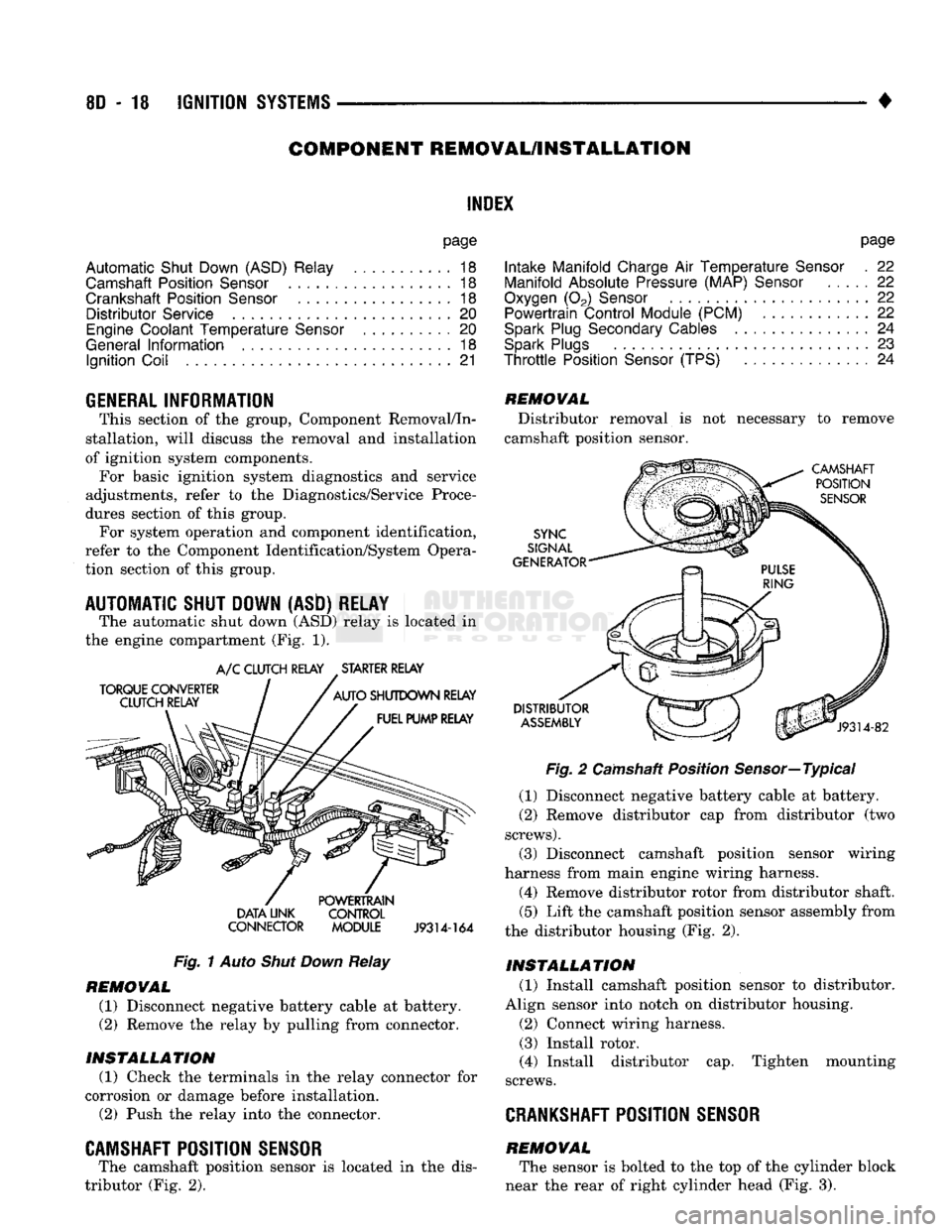
The automatic shut down
(ASD)
relay
is
located
in
the engine compartment
(Fig. 1).
TORQUE CONVERTER
CLUTCH RELAY
A/C
CLUTCH RELAY STARTER RELAY
AUTO
SHUTDOWN RELAY FUEL PUMP RELAY DATA UNK
CONNECTOR POWERTRAIN
CONTROL
MODULE
J9314-164
Fig.
1
Auto
Shut Down
Relay
REMOVAL
(1) Disconnect negative battery cable
at
battery.
(2)
Remove
the
relay
by
pulling from connector.
INSTALLATION
(1) Check
the
terminals
in the
relay connector
for
corrosion
or
damage before installation.
(2)
Push
the
relay into
the
connector.
CAMSHAFT POSITION SENSOR
The camshaft position sensor
is
located
in the
dis
tributor
(Fig. 2).
REMOVAL
Distributor removal
is not
necessary
to
remove
camshaft position sensor.
CAMSHAFT POSITION
SENSOR
SYNC
SIGNAL
GENERATOR
DISTRIBUTOR
ASSEMBLY
J9314-82
Fig.
2
Camshaft Position Sensor—Typical
(1) Disconnect negative battery cable
at
battery.
(2)
Remove distributor
cap
from distributor
(two
screws).
(3) Disconnect camshaft position sensor wiring
harness from main engine wiring harness.
(4) Remove distributor rotor from distributor shaft.
(5)
Lift
the
camshaft position sensor assembly from
the distributor housing
(Fig. 2).
INSTALLATION
(1) Install camshaft position sensor
to
distributor.
Align sensor into notch
on
distributor housing.
(2)
Connect wiring harness.
(3) Install rotor.
(4) Install distributor
cap.
Tighten mounting
screws.
CRANKSHAFT
POSITION SENSOR
REMOVAL The sensor
is
bolted
to the top of the
cylinder block
near
the
rear
of
right cylinder head
(Fig. 3).