1993 DODGE TRUCK crankshaft sensor
[x] Cancel search: crankshaft sensorPage 372 of 1502
IGNITION
SYSTEMS
80 - 21
DISTRIBUTOR
J9314-81
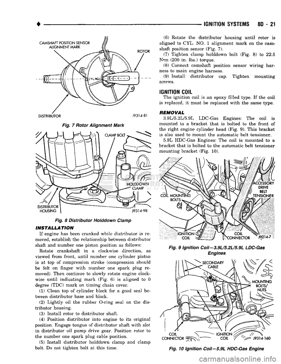
Fig.
7 Rotor Alignment Mark Fig. 8 Distributor Holddown Clamp
INSTALLATION
If engine has been cranked while distributor is re
moved, establish the relationship between distributor shaft and number one piston position as follows:
Rotate crankshaft in a clockwise direction, as
viewed from front, until number one cylinder piston is at top of compression stroke (compression should
be felt on finger with number one spark plug re moved). Then continue to slowly rotate engine clock
wise until indicating mark (Fig. 6) is aligned to 0
degree (TDC) mark on timing chain cover.
(1) Clean top of cylinder block for a good seal be
tween distributor base and block.
(2) Lightly oil the rubber O-ring seal on the dis
tributor housing.
(3) Install rotor to distributor shaft.
(4) Position distributor into engine to its original
position. Engage tongue of distributor shaft with slot in distributor oil pump drive gear. Position rotor to
the number one spark plug cable position.
(5) Install distributor holddown clamp and clamp
bolt. Do not tighten bolt at this time. (6) Rotate the distributor housing until rotor is
aligned to CYL. NO. 1 alignment mark on the cam
shaft position sensor (Fig. 7).
(7) Tighten clamp holddown bolt (Fig. 8) to 22.5
N*m (200 in. lbs.) torque. (8) Connect camshaft position sensor wiring har
ness to main engine harness. (9) Install distributor cap. Tighten mounting
screws.
IGNITION
COIL
The ignition coil is an epoxy filled type. If the coil
is replaced, it must be replaced with the same type.
REMOVAL
3.9L/5.2L/5.9L LDC-Gas Engines: The coil is
mounted to a bracket that is bolted to the front of
the right engine cylinder head (Fig. 9). This bracket is also used to mount the automatic belt tensioner.
5.9L HDC-Gas Engines: The coil is mounted to a
bracket that is bolted to the automatic belt tensioner mounting bracket (Fig. 10).
Fig.
9 Ignition Coil-3.9U5.2U5.9L
LDC-Gas
Engines
Fig.
10 Ignition Coil—5.9L
HDC-Gas
Engine
Page 380 of 1502
IGNITION
SYSTEMS
8D - 29
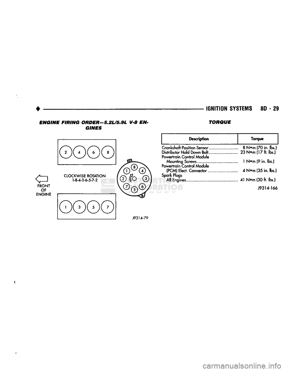
ENGINE FIRING ORDER—5.2L/5.9L V-8 EN
GINES TORQUE
FRONT
OF
ENGINE
CLOCKWISE
ROTATION
1-8-4-3-6-5-7-2
Description
Torque
Crankshaft
Position
Sensor..
Distributor Hold Down Bolt..
Powertrain
Control Module
Mounting
Screws............
Powertrain
Control Module
(PCM)
Elect. Connector...
Spark
Plugs
All Engines
8
N*m (70
in.
lbs.)
23
N«m(17ft.ibs.)
1
N«m (9 in. lbs.)
4 N*m (35
in.
lbs.)
41
N<>m
(30
ft.
lbs.)
J9314-166
J9314-79
1
Page 499 of 1502
CRANKSHAFT
POSITION
SENSOR
TO CRANKSHAFT POSITION
(SEE
VIEW
X)
VEHICLE
SPEED
SENSOR
CONVERTER
CLUTCH
SOLENOID
TO
VEHICLE SPEED SENSOR BEYOND THIS POINT
SEE MAIN VIEW
TO HEATED OXYGEN SENSOR
(SEE VIEW X)
VIEW
A
4X4 TRANSFER
CASE
(TYPICAL)
VEHICLE
SPEED
SENSOR
1 >
a
so
>
w
J938W-102
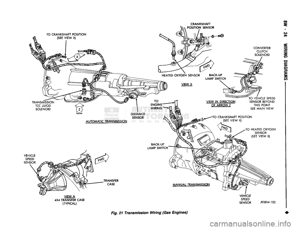
Fig. 21 Transmission Wiring (Gas Engines) 2
Page 512 of 1502
WIRING
DIAGRAMS
8W
- 37
WIRING DIAGRAMS AD-BODY
INDEX
Wiring Diagram Name Sheet Number
A/C
Heater System
with
Diesel Engine ............ .69,70 Blower Motor
. .69
Compressor
.70
Cycling Switch
.70
Diodes
70
Fuse
69
Low Pressure Switch
70
Resistor
. 69
Switch-Blower
. 69
Vacuum
Control
Switch
.69
Wide Open
Throttle
Cut-Out Relay
70
A/C
Heater System
with Gas
Engine .67,68 Blower Motor
.67
Compressor
.68
Cycling Switch
68
Low Pressure Switch
.68
Diodes
. .68
Fuse
. .67
Resistor
67
Switch-Blower
67
Vacuum
Control
Switch
.67
Wide Open
Throttle
Cutout Relay
68
Air Heater Relay Diesel Engine
.21
Air
Intake
Heater Diesel Engine
22
Anti-Lock Rear Brake System
with
Diesel Engine
.....
.33,34 Brake Warning Lamp Switch
34
Data Link Connector
33
Duel Solenoid Hydraulic Valve
34
Electronic Vacuum
Sensor
.34
Fuse
33
Module
.33
Park
Brake Switch
.33
Resistor
34
Rolls
Test Connector
33
Sensor
34
Stop
Lamp
34
Anti-Lock Rear Brake System
with Gas
Engine .31,32 Brake Warning Lamp Switch
.32
Data Link Connector
. .31
Dual Solenoid Hydraulic Valve
32
Fuse
31
Module
31
Park
Brake Switch
.31
Resistor
32
Rolls
Test Connector
31
Sensor
32
Stop
Lamp Switch
32
Back-Up
Lamp Switch
with
Diesel Engine
.7
Back-Up
Lamp Switch
with Gas
Engine
.9
Battery
.1,3,5
Brake Warning
Indicator
Lamp (Diesel Engine)
.57
Brake Warning
Indicator
Lamp
(Gas
Engine)
58
Brake Warning
Indicator
Lamp Switch (Diesel Engine)
. . . .34
Wiring Diagram Name Sheet Number
Brake Warning
Indicator
Lamp Switch
(Gas
Engine)
32
Bulkhead Disconnect 50-Way .85,86
Buzzer-Combined Headlamp,
Key In, and
Seat
Belt
. . .
.27,28
Bypass
Jumper
(Clutch
Pedal Position)
8
Cargo
Lamp .49,50
Cargo
Lamp Switch
49
Charging System
with
Diesel Engine ..............
.5,6
Battery
5
Generator
. .6
Charging System
with
Gas Engine
.3,4
Battery
3
Generator
, . .4
Cigar
Lighter,
Ash &
Glove
Box
Lamps
52
Circuit
Breakers Power Windows
2,71
Clearance Lamps Duel Rear Wheels
.
.41,43 Clearance Lamps Roof Mounted
40
Clockspring 30,36,38
Clutch Pedal Position Switch
.8
Cold
Start
Advance Motor
24
Compressor,
A/C
68,70 Data Link Connector 17,23,31,33
Data Link Connectors
Rear
Wheel Anti-Lock Diesel Engine
.33
Rear
Wheel Anti-Lock Gas Engine
31
Daytime Running
Light
Module
46
Diesel
Control
System .21,22,23,24,25,26
Air Heater Relay
. .21
Air
Intake
Heater
21
Automatic
Shut Down Relay
22
Cold
Start
24
Crankshaft Position
Sensor
. .25
Data Link Connector
. .23
Engine
Coolant Temp Switch
.26
Fuel Heater
24
Fuel Solenoid
24
Intake
Air
Temp
Sensor
25
Powertrain
Control
Module 21,22,23,25,26
Resistor
.24
Thermo Switch
24
Throttle
Position (Sensor)
26
Transmission Thermo Switch
. . .26
Vehicle Speed
Sensor
25,26 Water
in
Fuel
Sensor
.25
Dimmer Switch-Headlamp
. .47
Diode 68,70
Diode
and
Mold Assembly
51
Dome
and
Cargo Lamp
50
Door
Jamb Switches
49
Left
Switch
.49
Right Switch
49
Dual Solenoid Hydraulic Valve
.32
EMCC
System (3-Speed)
. .11
Page 513 of 1502
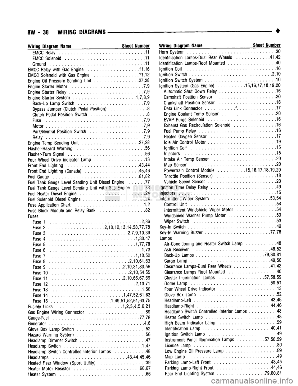
8W
- 38
WIRING
DIAGRAMS
• Wiring Diagram Name Sheet Number
EMCC
Relay
11
EMCC
Solenoid
11
Ground
11
EMCC
Relay
with Gas
Engine
11,16
EMCC
Solenoid
with Gas
Engine
11,12
Engine
Oil
Pressure Sending
Unit
.27,28
Engine
Starter
Motor
7,9
Engine
Starter
Relay
.7,9
Engine
Starter
System 1,7,8,9 Back-Up Lamp
Switch
.7,9
Bypass
Jumper
(Clutch
Pedal
Position)
8
Clutch
Pedal
Position
Switch
8
Fuse
. 7,9
Motor
7,9
Park/Neutral
Position
Switch
. .7,9
Relay
7,9
Engine Temp Sending
Unit
.
.27,28
Flasher-Hazard Warning
.56
Flasher-Turn Signal
56
Four Wheel
Drive
Indicator
Lamp
13
Front
End
Lighting
. .
.43,44
Front
End
Lighting
(Canada) 45,46
Fuel
Gauge
81,82
Fuel
Tank Gauge
Level
Sending
Unit
Diesel Engine
77
Fuel
Tank Gauge
Level
Sending
Unit
with Gas
Engine
78
Fuel
Heater
Diesel Engine
24
Fuel
Solenoid Diesel Engine
.24
Fuse
Application
Chart
1,2
Fuse
Block Module
and
Relay Bank
82
Fuses
Fuse
1 2,36
Fuse
2
.........
2,10,12,13,14,58,77,78
Fuse
3
2,7,9,10,39
Fuse
4
1,30,47
Fuse
5
1,77,78
Fuse
6
......
.1,73
Fuse
7
1,10,52
Fuse
8
.2,10,61,63
Fuse
9
.2,10,31,33,56
Fuse
10
.2,10,54,55
Fuse
11
2,10,66,67,69
Fuse
12
2,10,71
Fuse
13 1,56
Fuse
14
1,47,52,61,63
Fuse
15
1,49,51,52,61,63,75
Fusible Links 1,2,3,4,5,6,21
Gas
Engine
Wiring
Connector
89
Gauge-Fuel .77,78
Generator
.4,6
Glove
Box
Lamp
Switch
52
Hazard Warning System
. .56
Headlamp Dimmer
Switch
47
Headlamp
Switch
1,47
Headlamp
Switch
Controlled
Interior
Lamps
Headlamps 43,44,
Heated
Rear Window
(Sport
Utility)
Heater
Motor
Resistor
Heater
System Wiring Diagram Name Sheet Number
Horn System
30
Identification
Lamps-Dual Rear Wheels
41,42
Identification
Lamps-Roof Mounted
. 40
Ignition
Coil
.16
Ignition
Switch
.2,10
Ignition
Switch
System
10
Ignition
System (Gas Engine)
.........
.15,16,17,18,19,20
Automatic
Shut Down Relay
.16
Camshaft
Position
Sensor
20
Crankshaft
Position
Sensor
.18
Data
Link
Connector
* . . .17
Engine Coolant Temp
Sensor
20
EVAP
Purge Solenoid
16
Exhaust Gas
Recirculation
Solenoid
16
Fuel
Pump Relay
.16
Heated
Oxygen
Sensor
. . . 17
Idle
Air
Control
Motor
.19
Ignition
Coil
.15
Injectors
.15
Intake
Air
Temp
Sensor
. .20
Map
Sensor
. .20
Powertrain
Control
Module .15,16,17,18,19,20
Throttle
Position
(Sensor)
.18
Vehicle
Speed
Sensor
.20
Ignition
Time
Delay Relay
49
Injectors
.15 Intermittent
Wiper
System .53,54
Control
Unit
.54 Intermittent
Windshield
Wiper
Motor
54
Windshield
Washer Pump
Motor
53
Wiper
Switch
53
Key-In
Switch
49
Key-In Warning Buzzer 77,78
Lamps
Air-Conditioning
and
Heater
Switch
Lamp
48
Ash
Receiver .48,52 Back-Up Lamps
......
79,80,81
Cargo Lamp
.
.49,50 Clearance Lamps-Dual Rear Wheels .41,42
Clearance Lamps Roof Mounted
.40
Cluster
Illumination
Lamps
.
.57,58,59
Dome Lamp
50,51
Four Wheel
Drive
Indicator
.13
Glove
Box
Lamp
52
Headlamp-Left
43,45 Headlamp-Right 44,46
Headlamp
Switch
Controlled
Interior
Lamps
. 48
Heater
Switch
Lamp
.48
High Beam
Indicator
Lamp
.59
Identification
Lamp
.
.40,41
Ignition
Switch
Lamp
.49
Instrument
Panel
Illumination
Lamps
.
.57,58,59
License Lamp
. . . 80
.
.48 Low
Engine
Oil
Pressure Lamp
59
45,46
Map
Lamp
49
.
.39
Parking
Lamp-Left
Front
43,45
66,67 Parking Lamp-Right
Front
44,46 .
.66
Rear
End
Lighting
System .79,80,81
Page 515 of 1502
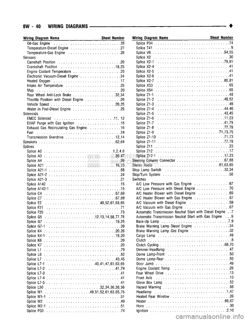
8W
- 40
WIRING DIAGRAMS
Wiring Diagram Name Sheet Number
Oil-Gas
Engine
28
Temperature-Diesel Engine
. . . ., 27
Temperature-Gas Engine
. .28
Sensors
Camshaft Position
. . .20
Crankshaft Position
. .
.18,25
Engine
Coolant
Temperature
20
Electronic
Vacuum-Diesel Engine
. .34
Heated Oxygen
17
Intake
Air
Temperature
25
Map
20
Rear
Wheel Anti-Lock Brake 32,34
Throttle
Position
with
Diesel Engine
26
Vehicle Speed .20,25 Water
In
Fuel-Diesel Engine
25
Solenoids
EMCC
Solenoid
11, 12
EVAP
Purge
with
Gas
Ignition
.16
Exhaust
Gas
Recirculating
Gas Engine
.16
Fuel
.24
Transmission Overdrive
12,14
Speakers
62,64
Splices
Splice AO 1,2,4,6
Splice
A3
30,47
Splice
A4 39
Splice A21
16,23
Splice A21-1
. .68
Splice
A21-2 24
Splice A21-3
21
Splice A142
.15
Splice
A142-1 15
Splice
C4
.67,69
Splice
C7
.67,69
Splice
E2
.48,52,61,63,65
Splice F21
. , 71
Splice
F35 73
Splice
G5
12,13,14,58,77,78 Splice
G7
........... .19,25
Splice G7-1
. . .20
Splice
K4
20,26 Splice K4-1
.... ..... ; . 18,20
Splice
K6 , 20
Splice
K7 .20
Splice
L1 .79
Splice
L6 . .50
Splice
L7
43,45
Splice L7-1 40,41,47,61,63,65
Splice
L7-2
.41,79
Splice
L7-3 .41
Splice
L7-4 41
Splice
L7-5 .41
Splice
L50
......
.
........... .32,34,36,38,56
Splice
M1
49,51,52,61,63,65,75 Splice M1-1
51
Splice
M2 . .49
Splice M2-1
.51
Splice
P33 . 74
Wiring Diagram Name Sheet Number
Splice
P34 .... .74
Splice T41 ..............
.9
Splice
V6 . .
.54,55
Splice
X2 . .30
Splice X2-1
. . . .
.79,81
Splice X2-4
41
Splice X2-5
.41
Splice X2-6
.... .41
Splice X2-7
80,81
Splice X53
.65
Splice
X54
..........
. . 65
Splice Z1-1
.48
Splice Z1-2 48,52
Splice Z1-3
. . 48
Splice Z1-4
...
.44,46
Splice
Z1-5 ..... . . . .
-43,45
Splice Z1-6
11,23
Splice
Z1-7 .
.41,79
Splice Z1-8 77,78 Splice Z1-9
. .
............ .71,73,75
Splice Z1-10
. 71,73
Splice Z1-11 .77,78
Splice Z11
23
Splice
Z12 ' 17
Splice Z12-1
17,23
Steering Column Connector
.
87,88
Stereo Radio 61,63,65
Stop
Lamp Switch 32,34
Stop/Turn System
.56
Switches
A/C
Low
Pressure
with
Gas Engine
67
A/C
Low
Pressure
with
Diesel Engine
70
A/C
Heater Blower
with
Diesel Engine
69
A/C
Heater Blower
with
Gas Engine
67
A/C
Vacuum
with
Diesel Engine
69
A/C
Vacuum
with
Gas Engine
67
Automatic
Transmission
Neutral
Start
with
Diesel Engine
. .7
Automatic
Transmission
Neutral
Start
with
Gas Engine
. . .9
Back-Up
Lamp
.7,9
Brake Warning Lamp Diesel Engine
34
Brake Warning Lamp Gas Engine
. .32
Cargo
Lamp
49
Clutch
8
Clutch
Cycling
...
.68,70 Dimmer-Headlamp
47
Dome
Lamp-Front
. .50
Dome
Lamp-Rear
50
Door
Jamb
. 49
Engine
Coolant Temp
.26
Four
Wheel Drive
13
Front
Axle
13
Glove
Box
Lamp
. .52
Hazard Warning
.56
Headlamp
1,47
Heated Rear Window
39
Heater
. .
.66,67
Horn
.30
Ignition
2,10
Page 534 of 1502
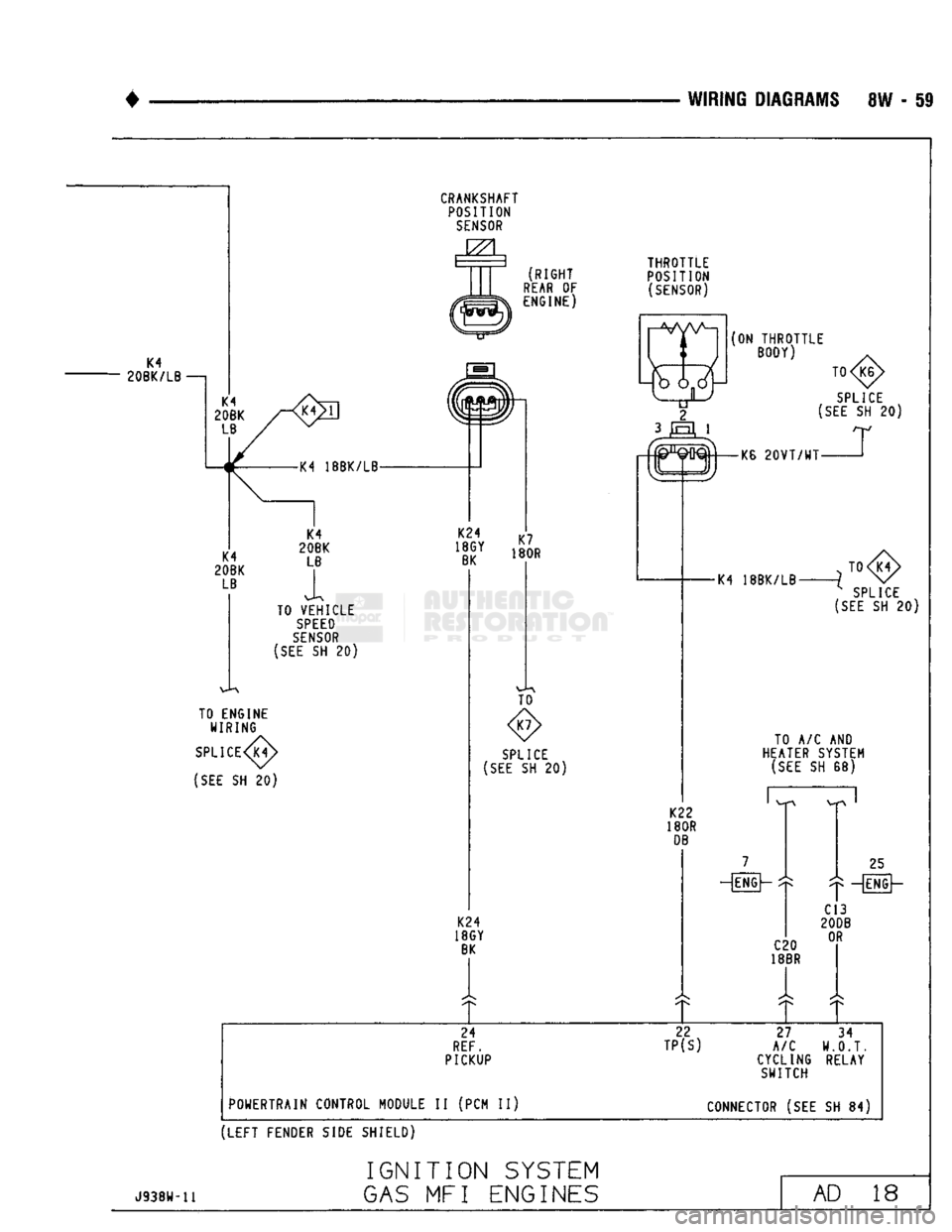
WIRING
DIAGRAMS 8W - 59
K4
20BK/LB —j K4 18BK/LB
TO VEHICLE
SPEED
SENSOR
(SEE
SH 20) TO ENGINE
WIRING
SPLICE
(SEE
SH 20) CRANKSHAFT
POSITION
SENSOR
RIGHT
REAR
OF ENGINE) TO
SPLICE
[SEE
SH 20)
K24
18GY
BK
THROTTLE
POSITION
(SENSOR)
(ON
THROTTLE
BODY)
T0
SPLICE
(SEE
SH 20)
rtM-
-KB
20VT/WT-
-K4 18BK/LB-
TO <8>
x SPLICE
(SEE
SH 20)
TO A/C AND
HEATER SYSTEM
(SEE
SH 68)
K22
180R
DB
-[ENGh
25
—[FNG]—
C20
18BR C13
20DB
OR
24 22
27 34
REF.
TP(S)
A/C
W.O.T.
PICKUP CYCLING RELAY
SWITCH
POWERTRAIN CONTROL MODULE II (PCM II) CONNECTOR (SEE SH 84)
(LEFT
FENDER SIDE SHIELD)
J938U-11
IGNITION
SYSTEM
GAS
MFI ENGINES
AD
18
Page 541 of 1502
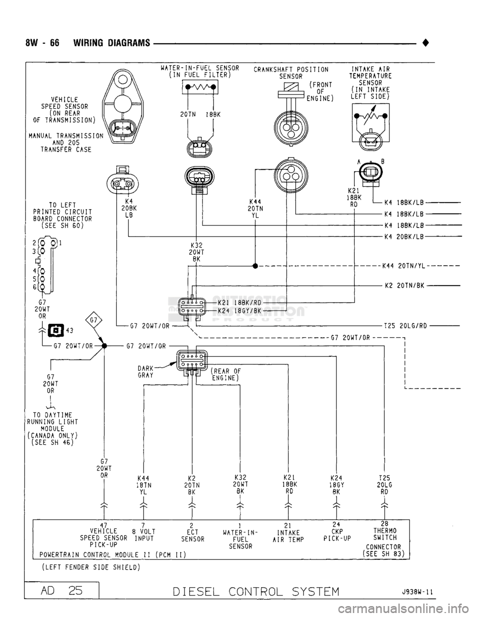
8W - 66 WIRING DIAGRAMS
•
WATER-1N-FUEL
SENSOR
(IN FUEL FILTER)
VEHICLE
SPEED SENSOR
(ON REAR
OF TRANSMISSION
MANUAL TRANSMISSION AND 205
TRANSFER
CASE
CRANKSHAFT POSITION
SENSOR
FRONT OF
ENGINE) INTAKE AIR
TEMPERATURE
SENSOR
IN INTAKE
LEFT SIDE)
TO LEFT
PRINTED CIRCUIT
BOARD
CONNECTOR
[SEE
SH 60)
TO DAYTIME
RUNNING
LIGHT
MODULE
(CANADA ONLY)
(SEE
SH 46)
47 7 2 1 21 24
28
VEHICLE 8 VOLT ECT WATER -1N- INTAKE
CKP
THERMO
SPEED SENSOR
INPUT
SENSOR
FUEL AIR TEMP PICK-UP
SWITCH
PICK-UP
SENSOR
CONNECTOR
POWERTRAIN CONTROL MODULE II (PCM II)
(SEE
SH 83)
(LEFT
FENDER SIDE SHIELD)
AD 25
DIESEL
CONTROL SYSTEM
J938H-11