1993 DODGE TRUCK brakes
[x] Cancel search: brakesPage 389 of 1502
8E
- 8 INSTRUMENT PANEL AND GAUGES
•
BRAKE
WARNING
LAMP
SWITCH TO BRAKE
WARNING LAMP
PR!
451
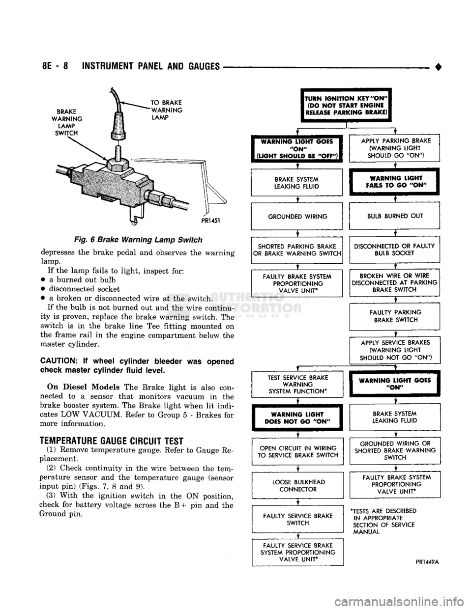
Fig.
6
Brake Warning
Lamp
Switch
depresses
the
brake pedal
and
observes
the
warning
lamp.
If
the
lamp fails
to
light, inspect
for:
•
a
burned
out
bulb
• disconnected socket
•
a
broken
or
disconnected wire
at the
switch. If
the
bulb
is not
burned
out and the
wire continu
ity
is
proven, replace
the
brake warning switch.
The
switch
is in the
brake line
Tee
fitting mounted
on
the frame rail
in the
engine compartment below
the
master cylinder.
CAUTION:
If
wheel cylinder bleeder
was
opened
check
master cylinder fluid level.
On Diesel Models
The
Brake light
is
also con
nected
to a
sensor that monitors vacuum
in the
brake booster system.
The
Brake light when
lit
indi cates
LOW
VACUUM. Refer
to
Group
5 -
Brakes
for
more information.
TEMPERATURE
GAUGE CIRCUIT TEST
(1) Remove temperature gauge. Refer
to
Gauge
Re
placement. (2) Check continuity
in the
wire between
the
tem
perature sensor
and the
temperature gauge (sensor
input
pin)
(Figs.
7, 8 and 9).
(3) With
the
ignition switch
in the ON
position,
check
for
battery voltage across
the B + pin and the
Ground
pin.
(TURN
IGNITION
KEY
"ON"
(DO
NOT
START
ENGINE
I
RELEASE
PARKING
BRAKE)
I
I
[
WARNING
LIGHT
GOES
I
"ON"
I
1
(LIGHT
SHOULD
BE
"OFF")!
X
APPLY PARKING BRAKE (WARNING
LIGHT
SHOULD
GO "ON")
BRAKE
SYSTEM
LEAKING FLUID
X
WARNING
LIGHT
FAILS
TO GO "ON" GROUNDED WIRING
BULB
BURNED
OUT
SHORTED PARKING BRAKE
OR BRAKE WARNING SWITCH
X
DISCONNECTED
OR
FAULTY
BULB
SOCKET
FAULTY BRAKE SYSTEM PROPORTIONING VALVE
UNIT*
BROKEN
WIRE
OR
WIRE
DISCONNECTED
AT
PARKING
BRAKE
SWITCH
X
FAULTY PARKING
BRAKE
SWITCH
X
APPLY SERVICE BRAKES
(WARNING
LIGHT
SHOULD
NOT GO "ON")
JZ
X
TEST SERVICE BRAKE WARNING
SYSTEM FUNCTION*
X
WARNING
LIGHT
GOES
"ON"
WARNING
LIGHT
DOES
NOT GO "ON"
BRAKE
SYSTEM
LEAKING FLUID
OPEN CIRCUIT
IN
WIRING
TO SERVICE BRAKE SWITCH
X
GROUNDED WIRING
OR
SHORTED BRAKE WARNING SWITCH
LOOSE
BULKHEAD CONNECTOR
X
FAULTY BRAKE SYSTEM
PROPORTIONING VALVE
UNIT*
FAULTY SERVICE BRAKE SWITCH
X
•TESTS
ARE
DESCRIBED
IN APPROPRIATE
SECTION
OF
SERVICE MANUAL
FAULTY SERVICE BRAKE
SYSTEM PROPORTIONING VALVE
UNIT*
PR1449A
Page 420 of 1502
•
^ ^ VEHICLE
SPEED
CONTROL
SYSTEM
8H - I
WARNING:
THE USE OF THE
SPEED
CONTROL
IS
NOT
RECOMMENDED
WHEN DRIVING
CONDITIONS
DO NOT PERMIT MAINTAINING
A
CONSTANT
SPEED,
SUCH AS HEAVY
TRAFFIC
OR ON
ROADS
THAT
ARE WINDING,
ICY,
SNOW
COVERED
OR
SLIPPERY*
SPEED
CONTROL
ENGAGES
WITHOUT PUSHING THE
"SET/DECEL"
BUTTON
±
FAULTY
ELECTRICAL CIRCUIT*
±
DEFECTIVE
SERVO
START ENGINE
ACCELERATE
VEHICLE TO DESIRED SPEED
PUSH
ON/OFF
BUTTON
TO "ON" POSITION.
PUSH
AND
RELEASE
"SET/DECEL"
BUTTON
REMOVE
FOOT
FROM
ACCELERATOR.
SPEED
SHOULD BE CONTROLLED
SPEED
CONTROL
ENGAGES
WHEN
ENGINE IS STARTED
FAULTY
ELECTRICAL
CIRCUIT*
T
DEFECTIVE SERVO
NO
SPEED
CONTROL WHEN
SET/DECEL
BUTTON
IS
PRESSED
AND
RELEASED
FUSE
BLOWN
NO VACUUM AT
SERVO
T
SPEED
CONTROL
THROTTLE
CABLE DISCONNECTED
IMPROPER
STOP LAMP AND SPEED CONTROL SWITCH ADJUSTMENT
FAULTY
ELECTRICAL CIRCUIT*
T
DEFECTIVE SERVO
DEFECTIVE
VACUUM PUMP
HUNTING
SURGE
OR
SPEED
VARIATIONS AT LOW
SPEEDS
I
LOCK-UP
TORQUE CONVERTER
ROUGHNESS
AMPLIFICATION OF ENGINE
SURGE
DEFECTIVE SERVO
DEFECTIVE
CABLE
DEFECTIVE
ENGINE CONTROLLER
EXCESSIVE
SAG
ON HILLS OR
IN TRAILER
TOWING
ENGINE
PERFORAAANCE
VACUUM
LEAK
EXCESSIVE
LOAD MAY
REQUIRE
MANUAL
ASSISTANCE
ON HILLS
DEFECTIVE
VACUUM PUMP
SPEED
SETTING AFTER
LOCK-IN,
TOO
HIGH
OR TOO LOW
T
VACUUM LEAK
DEFECTIVE SERVO DEFECTIVE
CABLE
T
DEFECTIVE
VACUUM PUMP
REFER
TO GROUP 5 - BRAKES
FOR VACUUM PUMP DIAGNOSIS.
"TEST AND ADJUSTMENTS ARE DESCRIBED IN APPROPRIATE SECTION OF SERVICE MANUAL.
J928H-15
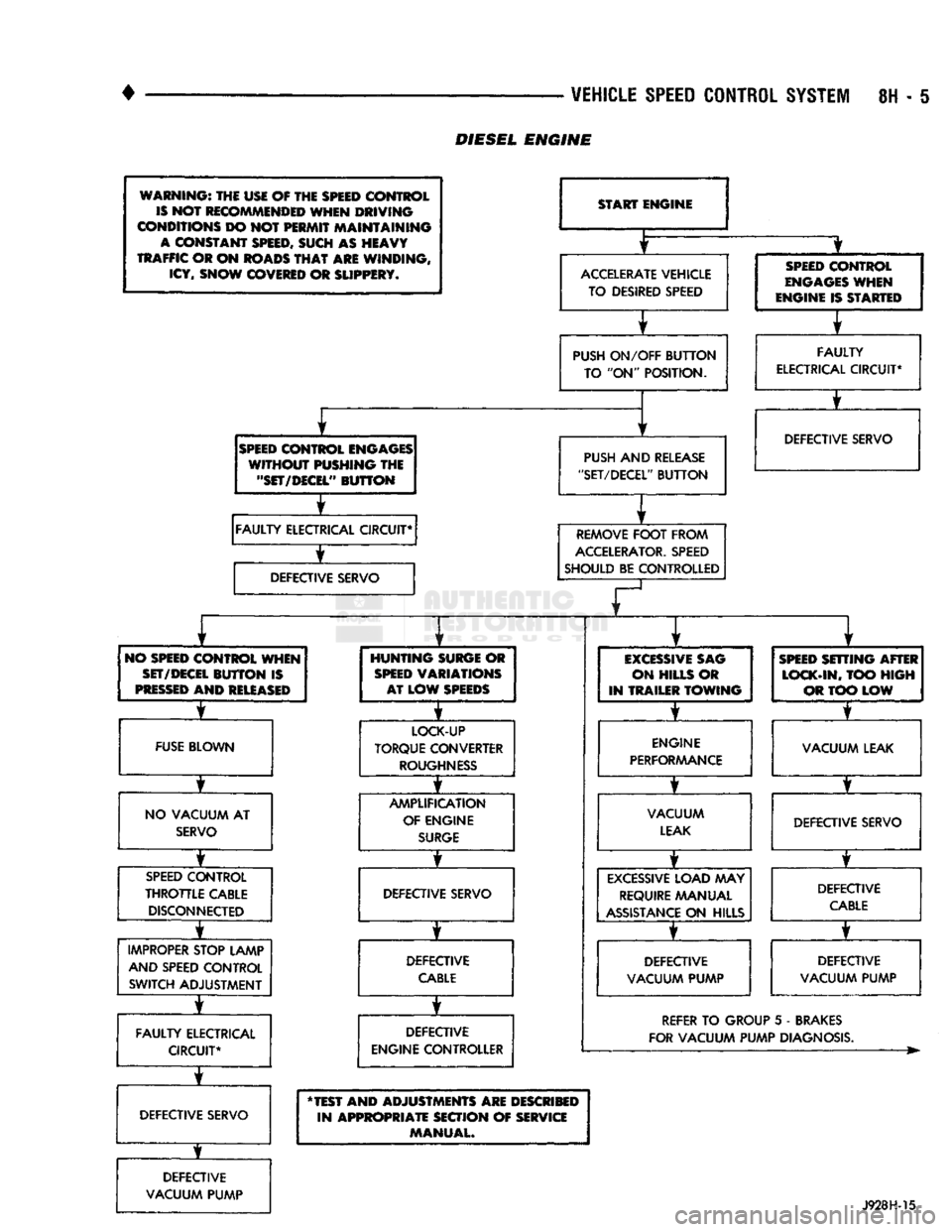
DIESEL
ENGINE
Page 424 of 1502
![DODGE TRUCK 1993 Service Repair Manual
VEHICLE
SPEED
CONTROL SYSTEM
8H - 9
rain
oooooooooo
1 10,
.oooooooooo
\21 30
„. \£] 50 x
OOOOOOOOOO OOOOOOOOOO^
11
20
OOOOOOOOOO
51
31 1 6ooooooooo60y/ Tratr
TJKT
RR8HC](/manual-img/12/56922/w960_56922-423.png "DODGE TRUCK 1993 Service Repair Manual
VEHICLE
SPEED
CONTROL SYSTEM
8H - 9
rain
oooooooooo
1 10,
.oooooooooo
\21 30
„. \£] 50 x
OOOOOOOOOO OOOOOOOOOO^
11
20
OOOOOOOOOO
51
31 1 6ooooooooo60y/ Tratr
TJKT
RR8HC")
VEHICLE
SPEED
CONTROL SYSTEM
8H - 9
rain
oooooooooo
1 10,
.oooooooooo
\21 30
„. \£] 50 x
OOOOOOOOOO OOOOOOOOOO^
11
20
OOOOOOOOOO
51
31 1 6ooooooooo60y/ Tratr
TJKT
RR8HC7
Fig.
4 Powertrain Control Module 60-Way Connector
Shown from Terminal End
from battery voltage to 0 volts for as long as the switch is held. If not, perform the speed control
switch test. If the switch is not at fault, then check
the main harness and repair as necessary.
(6) Touch the positive lead of the voltmeter to the
terminal in cavity number 50. The voltmeter should read 0 volts with the speed control switch in either
the OFF or ON position. With switch in either RE SUME or SET position, the voltmeter should read
battery voltage. If not, perform the speed control switch test. If the switch is not at fault, then check
the main harness and repair as necessary.
(7) Touch the positive lead of the voltmeter to the
terminal in cavity number 49. The voltmeter should read 0 volts with the switch in the OFF position.
With the switch in the ON position, the voltmeter should read battery voltage. The voltmeter will con
tinue to read battery voltage when either the SET or
RESUME switch is pressed. If not, perform the speed control switch test. If the switch is not at fault, then
check the main harness and repair as necessary . (8) Turn key OFF. Using an ohmmeter, connect
one lead to a good body ground and touch the other
lead to the terminal in cavity number 29. With the
brake pedal released, the meter should show continu ity. When the pedal is depressed, the meter should
show open circuit.
VEHICLE
SPEED
CONTROL SWITCH TEST
To check the switch, remove the switch from its
mounting position. Use an ohmmeter and refer to the
Switch Continuity Chart to determine if continuity is
correct. If there is no continuity at any one of the
switch positions, replace the switch.
STOP
LAMP SWITCH TEST
(1) Disconnect connector at stop lamp switch. Us
ing an ohmmeter, continuity may be checked at
switch side of connector as follows (Fig. 5): (a) With brake pedal released, there should be:
• continuity between black (BK) and white with
pink tracer (WT/PK) wires
• continuity between yellow with red tracer (YL/RD) and dark blue with red tracer (DB/RD) wires
• No continuity between pink (PK) and white (WT)
wires.
SPEED CONTROL SWITCH CONTINUITY
CHART
CONNECTOR
TERMINAL
END
JE
El
SWITCH
SPEED
CONTROL
SWITCH
CONTINUITY
SWITCH!
rea?!®^
CONTINUITY
BETWEEN
OFF PIN 1
AND PIN 4
ON PIN
1 AND PIN 4
PIN 1
AND PIN 2
PIN
2 AND PIN 4
ON
AND
SET PIN
1
AN D
PIN 2
ON
AND
RESUME PIN
1 AND PIN 3
J928H-4
(b) With brake pedal depressed, there should be:
• continuity between pink (PK) and white (WT)
wires.
• No continuity between black (BK) and white with
pink tracer (WT/PK) wires.
• No continuity between yellow with red tracer (YL/
RD) and dark blue with red tracer (DB/RD) wires. (2) If the above results are not obtained, the stop
lamp switch is defective or out of adjustment.
Stop lamp switch adjustment is detailed in Group 5 -
Brakes.
VACUUM SUPPLY TEST
(1) Disconnect vacuum hose at the servo and in
stall a vacuum gauge in the hose (Fig. 6). (2) Start engine and observe gauge at idle. Vac
uum gauge should read at least ten inches of mer
cury. (3) If vacuum does not meet this requirement,
check for vacuum leaks or poor engine performance.
SPEED
CONTROL
CABLE
ADJUSTMENT-DIESEL
ENGINE
(1) The gap between the end of the slot on the ca
ble and the bellcrank pin must be as small as possi
ble (0 to 1mm) without moving the throttle. If gap is not correct, remove adjustment clip. Push protective
Page 427 of 1502
8H
- 12
VEHICLE SPEED CONTROL SYSTEM
•
SERVO
THROTTLE CABLE ASSEMBLY—DIESEL
ENGINE
REMOVAL (1) Remove hairpin clip and washer retaining ca
bles on bellcrank. Remove servo throttle cable from bellcrank.
(2) Remove servo throttle cable from cable support
bracket.
(3) Remove 2 nuts from servo mounting bracket.
(4) Pull servo away from mounting bracket.
(5) Remove and discard push nuts on servo studs. (6) Pull speed control cable away from servo to ex
pose cable retaining clip. (7) Remove clip attaching cable to servo.
(8) Disconnect cable at servo and remove cable as
sembly.
INSTALLATION (1) Locate cable through servo mounting bracket.
(2) Connect cable sleeve to servo stud, align holes,
and install hairpin clip.
(3) Insert servo studs through holes in cable.
(4) Install new push nuts on servo studs.
(5) Insert servo studs through holes in bracket. In
stall nut washers and torque to 6 N*m (50 in. lbs.).
(6) Route cable from servo, to cable support
bracket, (7) Install cable end on bellcrank rod.
(8) Adjust cable as described under speed control
cable adjustment. (9) Install washer and hairpin clip on end of bell
crank rod.
SPEED
CONTROL
SWITCH
REPLACEMENT
(1) Disconnect negative cable from battery.
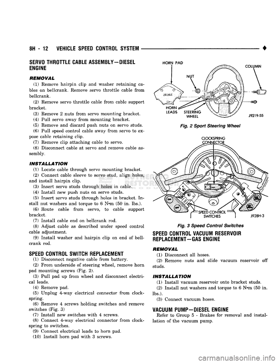
(2) From underside of steering wheel, remove horn
pad mounting screws (Fig. 2).
(3) Pull pad up from wheel and disconnect electri
cal leads.
(4) Remove pad.
(5) Unplug 4-way electrical connector from clock-
spring. (6) Remove 4 screws holding switches and remove
switches (Fig. 3) (7) Install new switches with 4 screws.
(8) Connect 4-way electrical connector from clock-
spring to switches. (9) Connect electrical leads to horn pad.
(10) Install horn pad with 3 screws.
HORN
PAD
Fig. 2 Sport Steering Wheel
CLOCKSPRING
Fig. 3 Speed Control Switches
SPEED
CONTROL VACUUM RESERVOIR
REPLACEMENT-GAS
ENGINE
REMOVAL (1) Disconnect all hoses.
(2) Remove nuts and slide vacuum reservoir off
studs.
INSTALLATION (1) Install vacuum reservoir onto bracket studs.
(2) Install nut washers and torque to 6 Nrn (50 in.
lbs.).
(3) Connect vacuum hoses.
VACUUM PUMP-DIESEL ENGINE
Refer to Group 5 - Brakes for removal and instal
lation of the vacuum pump.
Page 615 of 1502
9
- 10
ENGINES
— _
•
CONDITION
possmu
CLOSES
CORRECTION
ROUGH
IDLE
(IRREGULARLY
FIRING
OR
ENGINE
SHAKING)
(Cont'd)
High
pressure
fuel
leaks.
Air In the
fuel
system.
Correct leaks in the high pressure lines, fittings or
delivery
valves.
Bleed the
fuel
system and
eliminate
the source of the air.
Sticking
needle
valve
in an
injector.
Check and replace the
injector
with
the sticking
needle
valve.
ENGINE
RUNS
ROUGH
OR
MISFIRING
Fuel
injection
lines
leaking.
Correct leaks in the high pressure lines, fittings,
injector
sealing
washers
or
delivery
valves.
Air in the
fuel
or the
fuel
supply
is
inadequate.
Check the flow through the
filter
and bleed the system. Locate
and
eliminate
the air source.
Contaminated
fuel.
Verify
by operating the engine
with
clean
fuel
from a temporary
supply
tank. Check for presence of gasoline. Replace
fuel/water
separator
filter.
Incorrect
valve
adjustment.
Check for a
bent
push rod and adjust valves. Replace push rod,
if necessary.
Injection
pump
timing
incorrect.
Check/time pump
(refer
to Group 14,
Fuel
System).
Improperly
operating
injectors.
Replace inoperative injectors.
Defective
injection
pump
(delivery
valves).
Replace
injection
pump.
Camshaft
out of
time.
Check/correct gear
train
timing alignment.
Damaged
camshaft or
tappets.
Inspect camshaft valve
lift.
Replace camshaft and tappets.
ENGINE
RPM WILL NOT
REACH
RATED
SPEED
Engine
overloaded.
Verify
high
idle
speed
without
load. Investigate operation to be
sure correct gear is being used.
Improperly
operating
tachometer.
Verify
engine speed
with
hand tachometer—correct as required.
Throttle
linkage
worn
or
incorrectly
adjusted.
Adjust linkage for stop-to-stop
fuel
control
lever
travel.
Replace
linkage if necessary.
Partially
engaged
mechanical
shutdown
lever.
Adjust and place shutdown
lever
in the run position.
Inadequate
fuel
supply. Check the
fuel
flow through the system to locate the reason for
inadequate
fuel
supply—correct as required.
Improperly
operating
injection
pump.
Replace
injection
pump.
LOW
POWER
Fuel
control
lever
not
moving
to
full
throttle.
Check/correct for stop-to-stop
travel.
Mechanical/shutdown
lever
partially
engaged.
Check to see if the shutdown
lever
is in run position.
High
oil
level.
Check/correct oil level.
Engine
overloaded.
Check for added loading from accessories or driven units, brakes
dragging
and
other
changes in vehicle loading. Repair/replace as
needed.
J9109-264
SERVICE
DIAGNOSIS (DIESEL ENGINE)
•
PERFORMANCE (CONT.)
Page 851 of 1502
14
- 32
FUEL SYSTEM
•
BATTERY VOLTAGE—PCM
INPUT
The battery voltage input provides power
to the
powertrain control module (PCM).
It
also informs
the
PCM what voltage level
is
supplied
to the
ignition
coil
and
fuel injectors. If battery voltage
is low, the PCM
will increase injec
tor pulse width (period
of
time that
the
injector
is
ener
gized).
This
is
done
to
compensate
for the
reduced flow
through injector caused
by the
lowered voltage.
BRAKE
SWITCH-PCM
INPUT
When
the
brake light switch
is
activated,
the
pow
ertrain control module
(PCM)
receives
an
input indi
cating that
the
brakes
are
being applied. After
receiving this input,
the PCM
maintains idle speed
to
a
scheduled
rpm
through control
of the
idle
air
control
(IAC)
motor.
The
brake switch input
is
also
used
to
operate
the
speed control system.
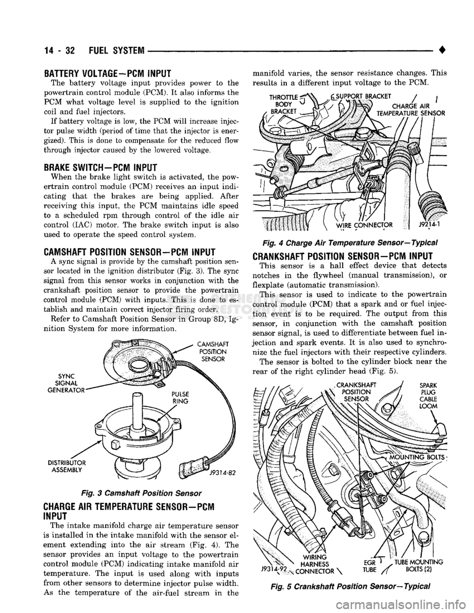
CAMSHAFT POSITION SENSOR—PCM
INPUT
A sync signal
is
provide
by the
camshaft position sen
sor located
in the
ignition distributor
(Fig.
3).
The
sync
signal from this sensor works
in
conjunction with
the
crankshaft position sensor
to
provide
the
powertrain
control module
(PCM)
with inputs. This
is
done
to es
tablish
and
maintain correct injector firing order. Refer
to
Camshaft Position Sensor
in
Group
8D, Ig
nition System
for
more information.
Fig.
3
Camshaft Position
Sensor
CHARGE AIR TEMPERATURE SENSOR-PCM
INPUT
The intake manifold charge
air
temperature sensor
is installed
in the
intake manifold with
the
sensor
el
ement extending into
the air
stream
(Fig. 4). The
sensor provides
an
input voltage
to the
powertrain control module
(PCM)
indicating intake manifold
air
temperature.
The
input
is
used along with inputs from other sensors
to
determine injector pulse width. As
the
temperature
of the
air-fuel stream
in the
manifold varies,
the
sensor resistance changes. This
results
in a
different input voltage
to the PCM.
Fig.
4
Charge
Air
Temperature
Sensor—Typical
CRANKSHAFT POSITION SENSOR-PCM INPUT
This sensor
is a
hall effect device that detects
notches
in the
flywheel (manual transmission),
or
flexplate (automatic transmission). This sensor
is
used
to
indicate
to the
powertrain
control module
(PCM)
that
a
spark
and or
fuel injec
tion event
is to be
required.
The
output from this sensor,
in
conjunction with
the
camshaft position
sensor signal,
is
used
to
differentiate between fuel
in
jection
and
spark events.
It is
also used
to
synchro nize
the
fuel injectors with their respective cylinders. The sensor
is
bolted
to the
cylinder block near
the
rear
of the
right cylinder head
(Fig. 5).
Fig.
5
Crankshaft Position Sensor—Typical
Page 883 of 1502
MULTI-PORT
FUEL
INJECTION
(MPI)-COMPONENT
REMOVAL/INSTALLATION
—EXCEPT DIESEL
INDEX
page
Accelerator Pedal
and Throttle
Cable
. 64
Air Conditioning (A/C) Clutch Relay
64
Air
Filter/Filter
Housing
64
Automatic Shut Down (ASD) Relay
. 64
Brake
Switch
64
Camshaft
Position
Sensor
..................
64
Charge
Air
Temperature
Sensor
64
Crankshaft Position
Sensor
64
Engine
Coolant Temperature
Sensor
65
EVAP
Canister Purge Solenoid
65
Fuel
Filter
65
Fuel Filter/Fuel Pressure Regulator—5.9L Engine
. 65
Fuel Injector(S)
67
Fuel Pressure Regulator
67
Fuel Pump Module
68
Fuel Pump Relay
68
ACCELERATOR
PEDAL
AND THROTTLE
CABLE
Refer
to
the
Accelerator Pedal
and
Throttle Cable
section
of
this group
for
removal/installation proce
dures.
AIR
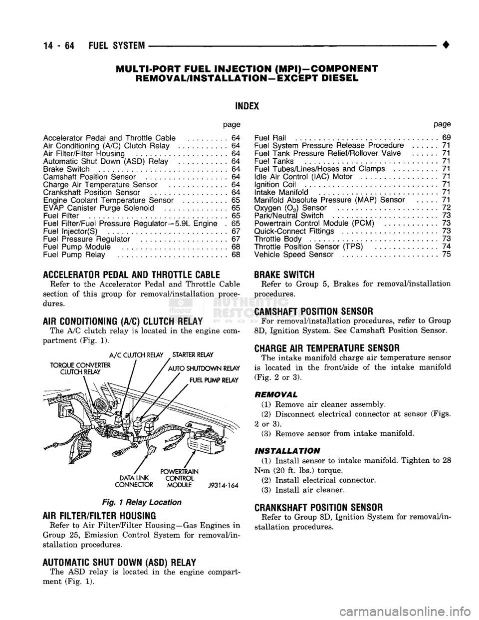
CONDITIONING (A/C) CLUTCH RELAY The A/C clutch relay
is
located
in
the
engine com
partment (Fig.
1).
A/C CLUTCH RELAY STARTER RELAY
DATA LINK CONTROL
CONNECTOR MODULE
J9314-164
Fig.
1 Relay Location
AIR
FILTER/FILTER
HOUSING
Refer
to
Air Filter/Filter Housing—Gas Engines
in
Group
25,
Emission Control System
for
removal/in
stallation procedures.
AUTOMATIC SHUT DOWN (ASD) RELAY The ASD relay
is
located
in
the
engine compart
ment (Fig.
1).
page
Fuel Rail
69
Fuel System Pressure Release Procedure
......
71
Fuel Tank Pressure Relief/Rollover Valve
71
Fuel Tanks
71
Fuel
Tubes/Lines/Hoses
and
Clamps
71
Idle
Air
Control (IAC) Motor
71
Ignition Coil
71
Intake Manifold
71
Manifold Absolute Pressure (MAP)
Sensor
71
Oxygen
(02)
Sensor
72
Park/Neutral Switch
. 73
Powertrain Control Module (PCM)
73
Quick-Connect
Fittings
73
Throttle
Body
73
Throttle
Position
Sensor
(TPS)
......
74
Vehicle
Speed
Sensor
75
BRAKE
SWITCH
Refer
to
Group
5,
Brakes
for
removal/installation
procedures.
CAMSHAFT
POSITION
SENSOR
For removal/installation procedures, refer
to
Group
8D,
Ignition System. See Camshaft Position Sensor.
CHARGE
AIR
TEMPERATURE SENSOR
The intake manifold charge
air
temperature sensor
is located
in the
front/side
of
the
intake manifold (Fig.
2
or
3).
REMOVAL
(1) Remove
air
cleaner assembly.
(2) Disconnect electrical connector
at
sensor (Figs.
2
or
3). (3) Remove sensor from intake manifold.
INSTALLATION
(1) Install sensor
to
intake manifold. Tighten
to 28
Nnn (20
ft.
lbs.) torque.
(2) Install electrical connector.
(3) Install
air
cleaner.
CRANKSHAFT
POSITION
SENSOR
Refer
to
Group 8D, Ignition System
for
removal/in
stallation procedures.
Page 901 of 1502
14 - 82
FUEL 'SYSTEM
—. — ~—— — «
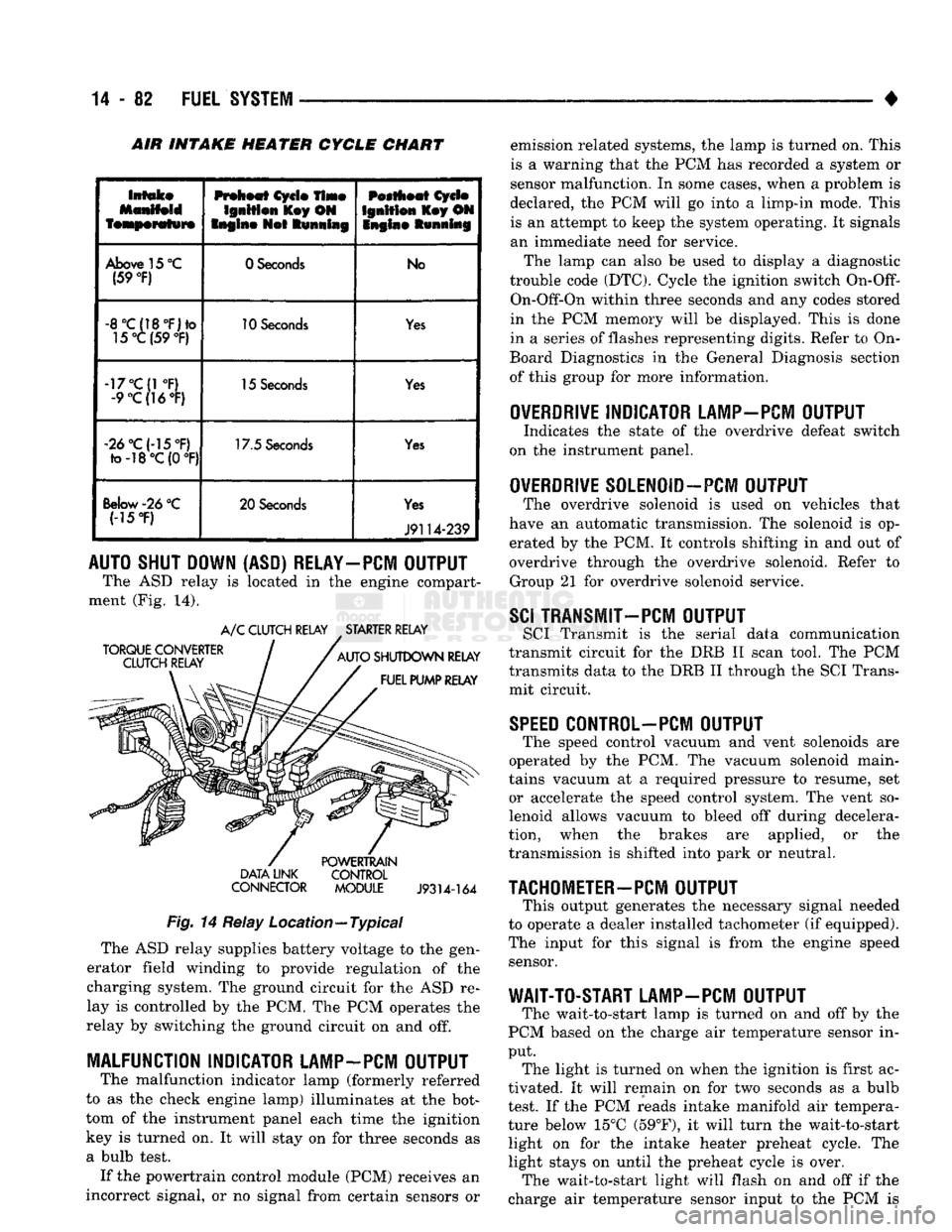
INTAKE HEATER CYCLE CHART
Intake
featperafwre
Preheat
Cycle
Time
Ignition
l£ey ON
Engine
Not
Running
Pestheat
Cycle
Ignition
Key ON
Snglne Running
Above
15
°C
(59
°F)
0 Seconds
No
-8°C(18°F)to
15°C (59
°F)
10
Seconds
Yes
-17°C(1
°F)
-9
°C(]6°F)
15
Seconds
Yes
«2d°C(-15°F)
to-18°C(0
°F) 17.5
Seconds
Yes
Below-26
°C (-15
*F)
20 Seconds
Yes
J9114-239
AUTO SHUT DOWN (ASD) RELAY-PCM OUTPUT
The ASD relay is located in the engine compart
ment (Fig. 14).
TORQUE CONVERTER
CLUTCH RELAY A/C CLUTCH RELAY STARTER RELAY
AUTO SHUTDOWN RELAY FUEL PUMP RELAY DATA LINK
CONNECTOR
POWERTRAIN
CONTROL MODULE
J9314-164
Fig.
14 Relay Location—Typical The ASD relay supplies battery voltage to the gen
erator field winding to provide regulation of the
charging system. The ground circuit for the ASD re
lay is controlled by the PCM. The PCM operates the
relay by switching the ground circuit on and off.
MALFUNCTION INDICATOR LAMP-PCM OUTPUT
The malfunction indicator lamp (formerly referred
to as the check engine lamp) illuminates at the bot
tom of the instrument panel each time the ignition
key is turned on. It will stay on for three seconds as
a bulb test. If the powertrain control module (PCM) receives an
incorrect signal, or no signal from certain sensors or emission related systems, the lamp is turned on. This
is a warning that the PCM has recorded a system or
sensor malfunction. In some cases, when a problem is
declared, the PCM will go into a limp-in mode. This is an attempt to keep the system operating. It signals
an immediate need for service.
The lamp can also be used to display a diagnostic
trouble code (DTC). Cycle the ignition switch
On-Off-
On-Off-On within three seconds and any codes stored
in the PCM memory will be displayed. This is done
in a series of flashes representing digits. Refer to On-
Board Diagnostics in the General Diagnosis section
of this group for more information.
OVERDRIVE
INDICATOR LAMP-PCM OUTPUT
Indicates the state of the overdrive defeat switch
on the instrument panel.
OVERDRIVE
S0LEN0ID-PCM OUTPUT
The overdrive solenoid is used on vehicles that
have an automatic transmission. The solenoid is op erated by the PCM. It controls shifting in and out of
overdrive through the overdrive solenoid. Refer to Group 21 for overdrive solenoid service.
SCI
TRANSMIT—PCM OUTPUT
SCI Transmit is the serial data communication
transmit circuit for the DRB II scan tool. The PCM
transmits data to the DRB II through the SCI Trans
mit circuit.
SPEED
C0NTR0L-PCM OUTPUT
The speed control vacuum and vent solenoids are
operated by the PCM. The vacuum solenoid main
tains vacuum at a required pressure to resume, set or accelerate the speed control system. The vent so
lenoid allows vacuum to bleed off during decelera
tion, when the brakes are applied, or the
transmission is shifted into park or neutral.
TACHOMETER-PCM
OUTPUT
This output generates the necessary signal needed
to operate a dealer installed tachometer (if equipped).
The input for this signal is from the engine speed sensor.
WAIT-TO-START LAMP-PCM OUTPUT
The wait-to-start lamp is turned on and off by the
PCM based on the charge air temperature sensor in
put. The light is turned on when the ignition is first ac
tivated. It will remain on for two seconds as a bulb
test. If the PCM reads intake manifold air tempera
ture below 15°C (59°F), it will turn the wait-to-start light on for the intake heater preheat cycle. The
light stays on until the preheat cycle is over. The wait-to-start light will flash on and off if the
charge air temperature sensor input to the PCM is