1993 DODGE TRUCK brakes
[x] Cancel search: brakesPage 906 of 1502
•
FUEL
SYSTEM
14 - 87
ENGINE
WARM-UP
• The PCM may start the air intake heater post-heat
cycle depending on intake air temperature. If manifold air temperature was at or below 15°C (59°F) when the
ignition switch was turned on, the cycle is started.
• If intake manifold air temperature is below 32°C
(90°F),
the KSB solenoid will be energized through
the air temperature switch. The solenoid remains en ergized until the air temperature switch opens. The
switch opens when intake manifold air temperature
is above 32°C (90°F).
• If the coolant temperature is below 16°C (60° F),
the transmission will not be allowed to enter over drive (automatic transmission).
• The PCM will turn on the water-in-fuel lamp if a signal is received from the water-in-fuel sensor.
CRUISE
OR
IDLE
• The PCM monitors intake manifold air tempera
ture through the charge temperature sensor input. • If intake manifold air temperature is below 32°C
(90°F),
the KSB solenoid will be energized through
the air temperature switch. The solenoid remains en ergized until the air temperature switch opens. The switch opens when intake manifold air temperature
is above 32°C (90°F).
• The air intake heater post-heat cycle will be com
pleted, if it is not already over.
• The vehicle speed sensor, engine speed sensor and
throttle position sensor inputs are used to control
transmission overdrive operation.
• If the coolant temperature is below 16° C (60° F),
the transmission will not be allowed to enter over drive (automatic transmission).
• If the transmission thermo-switch is open, the
transmission will not be allowed to enter into over
drive (automatic transmission). If the switch opens
when the vehicle is in overdrive, the transmission
will be downshifted. The transmission thermo-switch opens at 134°C (273°F).
• The thermo-switch will close once the transmission
fluid temperature drops to 116°C (240°F). • The PCM will turn on the water-in-fuel lamp if a signal is received from the water-in-fuel sensor.
ACCELERATION
• The vehicle speed sensor, engine speed sensor and
throttle position sensor inputs are used to control
transmission overdrive operation.
• If the coolant temperature is below 16° C (60° F),
the transmission will not be allowed to enter over
drive (automatic transmission).
• If intake manifold air temperature is below 32°C
(90°F),
the KSB solenoid will be energized through
the air temperature switch. The solenoid remains en ergized until the air temperature switch opens. The
switch opens when intake manifold air temperature
is above 32°C (90°F). • If the transmission thermo-switch is open, the
transmission will not be allowed to enter into over
drive (automatic transmission). If the switch opens
when the vehicle is in overdrive, the transmission
will be downshifted. The transmission thermo-switch opens at 134°C (273°F). The thermo-switch will close
once the transmission fluid temperature drops to 116°C (240°F).
• The PCM will turn on the water-in-fuel lamp if a
signal is received from the water-in-fuel sensor.
• If the speed control system resume/accelerate func
tion is being used, the PCM will only allow the vehi
cle to accelerate at a predetermined rate. If a speed
control has been set and the resume/accelerate but
ton is momentarily pushed in, the PCM will increase
vehicle speed by two miles per hour.
• If the brakes are applied, the PCM will disable the
speed control.
DECELERATION
• The vehicle speed sensor, engine speed sensor and
throttle position sensor inputs are used to control
transmission overdrive operation.
• If the coolant temperature is below 16° C (60° F),
the transmission will not be allowed to enter over drive (automatic transmission).
• If the transmission thermo-switch is open, the trans
mission will not be allowed to enter into overdrive (au
tomatic transmission). If the switch opens when the
vehicle is in overdrive, the transmission will be down shifted. The transmission thermo-switch opens at 134°C (273°F). The thermo-switch will close once the transmis
sion fluid temperature drops to 116°C (240°F).
• The PCM will turn on the water-in-fuel lamp if a
signal is received from the water-in-fuel sensor.
• If intake manifold air temperature is below 32°C
(90°F),
the KSB solenoid will be energized through
the air temperature switch. The solenoid remains en ergized until the air temperature switch opens. The
switch opens when intake manifold air temperature
is above 32°C (90°F).
• If the speed control system coast/set function is be
ing used, the PCM will only allow the vehicle to de celerate at a predetermined rate. If the coast/set
switch is pushed while the system is operating, the
PCM will set speed control to the rate the vehicle is
traveling at when the switch is released. • If the brakes are applied, the PCM will disable the speed control.
IGNITION SWITCH
OFF
• When the ignition switch is turned to the off posi
tion, the PCM still receives battery voltage through
the battery input. Battery voltage is needed to keep
PCM memory alive. The PCM memory stores diag nostic trouble code (DTC) messages and the mini
mum TPS value from the previous key-on.
Page 948 of 1502
•
PROPELLER SHAFTS
16 - 3
SERVICE
DIAGNOSIS/PROCEDURES
INDEX
page page
Precautions . 3 Universal
Joint
Angle Measurement ............ 4
Runout
4
Vibration
3
Unbalance
3
PRECAUTIONS
Propeller shafts are balanced by the manufacturer
to prevent vibration. Before undercoating a vehicle, the propeller shaft and the U-joints should be covered. This will prevent the undercoating from caus
ing an unbalanced condition and vibration. Use exact replacement hardware for attaching the
propeller shafts. Exact replacement will ensure safe operation. The specified torque must always be ap
plied when tightening the fasteners.
VIBRATION
Tires that are out-of-round or wheels that are un
balanced will cause a low frequency vibration. Refer to Group 22, Tires And Wheels for service informa
tion. Brake drums that are unbalanced will cause harsh,
low frequency vibration. Refer to Group 5, Brakes for
service information. Driveline vibration can also result from loose or
damaged engine mounts. Refer to Group 21, Trans
missions for additional information. Propeller shaft vibration will increase as the vehi
cle speed is increased. A vibration that occurs within a specific speed range is not caused by propeller
shaft unbalance. Defective U-joints or an incorrect
propeller shaft angle are usually the cause.
UNBALANCE
If propeller shaft unbalance is suspected, it can be
verified with the following procedure. Removing and re-indexing the propeller shaft
180° may eliminate some vibrations. (1) Raise and support the vehicle.
(2) Clean all foreign material from propeller shaft
and U-joints. (3) Inspect propeller shaft for missing balance
weights, broken welds, and bent areas. If the pro
peller shaft is bent, it must be replaced. (4) Ensure the U-joints are not worn and are prop
erly installed. (5) Check the U-joint clamp screws torque.
(6) Remove wheels and tires. Install wheel lug
nuts to retain brake drums in place. (7) Mark and number the shaft at four positions
90° apart, six inches from the yoke weld end.
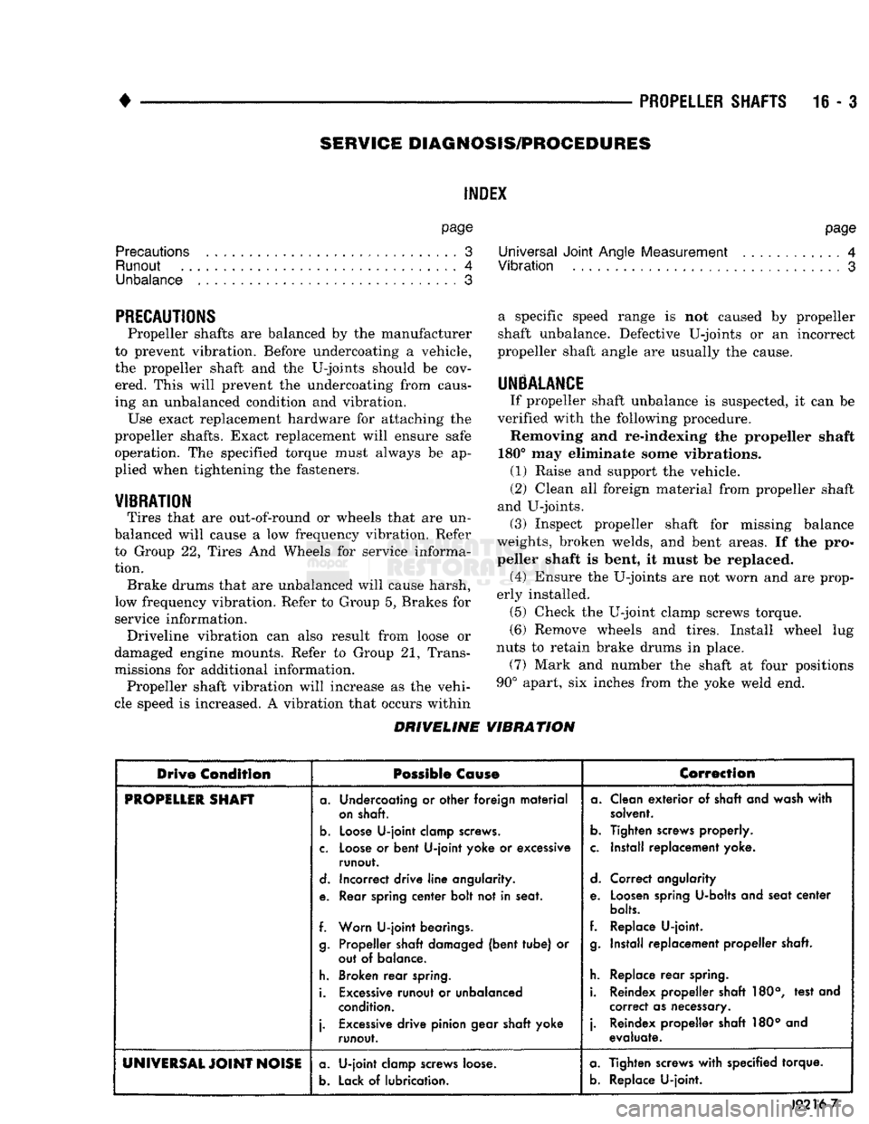
DRIVELINE VIBRATION
Drive
Condition
Possible Cause
Correction
PROPiLLlR
SHAFT
a. Undercoating or other foreign material
on shaft.
b.
Loose U-joint clamp screws.
c. Loose or bent U-joint yoke or excessive runout.
d. Incorrect drive line angularity.
e. Rear spring center bolt not in seat.
f. Worn U-joint bearings. g. Propeller shaft damaged (bent tube) or out of balance.
h. Broken rear spring.
i. Excessive runout or unbalanced condition.
j.
Excessive drive pinion gear shaft yoke runout. a. Clean exterior of shaft and wash with
solvent.
b.
Tighten screws properly.
c. Install replacement yoke.
d. Correct angularity
e. Loosen spring U-bolts and seat center
bolts.
f. Replace U-joint. g. Install replacement propeller shaft.
h. Replace rear spring.
i. Reindex propeller shaft 180°, test and correct as necessary.
j.
Reindex propeller shaft 180° and evaluate.
UNIVERSAL
JOINT
NOISE a. U-joint clamp screws loose.
b.
Lack of lubrication. a. Tighten screws with specified torque.
b.
Replace U-joint.
J9216-7
Page 969 of 1502
19
- 8
STEERING
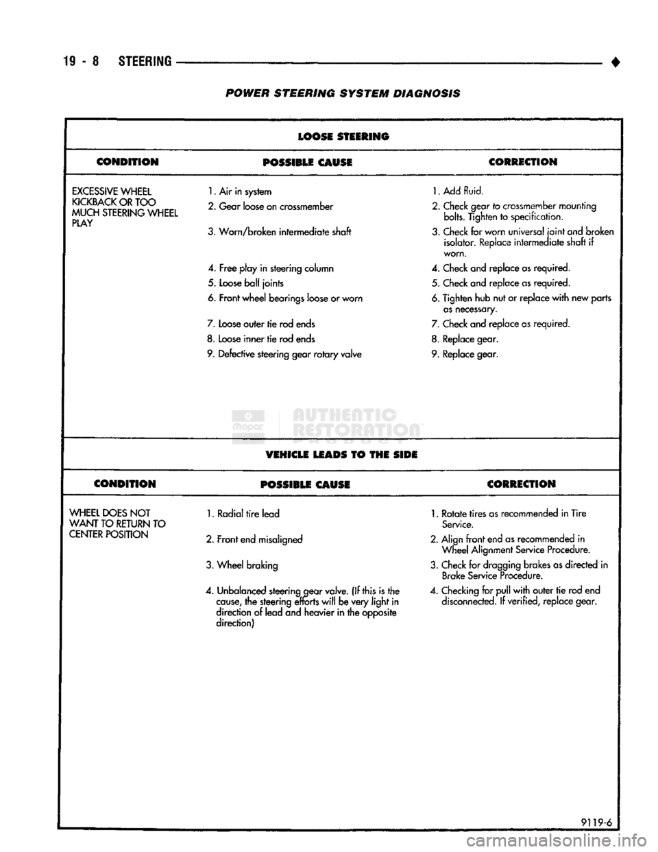
POWER
STEERING
SYSTEM
DIAGNOSIS
LOOSE
STEERING
CONDITION
POSSIBLE
CAUSE
CORRECTION
EXCESSIVE
WHEEL
KICKBACK
OR
TOO
MUCH
STEERING
WHEEL
PLAY
1.
Air in system
2.
Gear
loose
on
crossmember
3.
Worn/broken intermediate shaft
4.
Free
play in steering column
5.
Loose
ball
joints
6. Front wheel bearings
loose
or worn
7.
Loose
outer tie rod
ends
8.
Loose
inner
tie
rod
ends
9.
Defective steering gear
rotary
valve
1.
Add
fluid.
2.
Check
gear
to
crossmember
mounting bolts. Tighten
to
specification,
3.
Check
for worn universal
joint
ond
broken isolator.
Replace
intermediate shaft
if
worn.
4.
Check
and replace
as
required. 5.
Check
and replace
as
required.
6.
Tighten hub nut or replace
with
new parts
as
necessary.
7.
Check
and replace
as
required.
8.
Replace
gear.
9.
Replace
gear.
VEHICLE
LEADS
TO THE
SIDE
CONDITION
POSSIBLE
CAUSE
CORRECTION
WHEEL
DOES
NOT
WANT
TO
RETURN
TO
CENTER
POSITION
1. Radial
tire
lead
2. Front
end
misaligned
3.
Wheel braking
4.
Unbalanced
steering
gear
valve.
(If this is the
cause,
the steering
efforts
will
be very
light
in
direction
of
lead and heavier in the opposite
direction)
1.
Rotate
tires
as
recommended in Tire
Service.
2. Align
front
end
as
recommended
in
Wheel
Alignment
Service
Procedure.
3.
Check
for
dragging
brakes
as
directed
in
Brake
Service
Procedure.
4.
Checking
for
pull
with
outer
tie
rod end
disconnected.
If verified, replace gear.
9119-6
Page 975 of 1502
19
- 14
STEERING
• (9) Install the fluid hoses to the power steering
pump, Tighten the pressure fitting at the pump to 30
N*m (22 ft. lbs.) torque.
(10) Install and clamp the hose on the vacuum
pump. (11) Fill the reservoir with power steering fluid
only. If necessary, refer to Pump Initial Operation
for detailed instructions.
(12) Start and run the engine. Check the operation
of the brakes, if necessary refer to Group 5, Brakes
for additional information.
PUMP REPLACEMENT—GASOLINE ENGINE
REMOVAL
WARNING:
DO NOT
REMOVE
THE
WATER PUMP COOLANT TUBE UNLESS
THE
COOLANT SYSTEM HAS BEEN DEPRESSUR1ZED
AND
DRAINED*
WARNING:
DO NOT
ATTEMPT
TO
REMOVE
THE
PUMP
WITHOUT
REMOVING
THE
BELT FIRST.
THE
AUTOMATIC TENSIONER
IS
UNDER
A
HIGH
SPRING
LOAD.
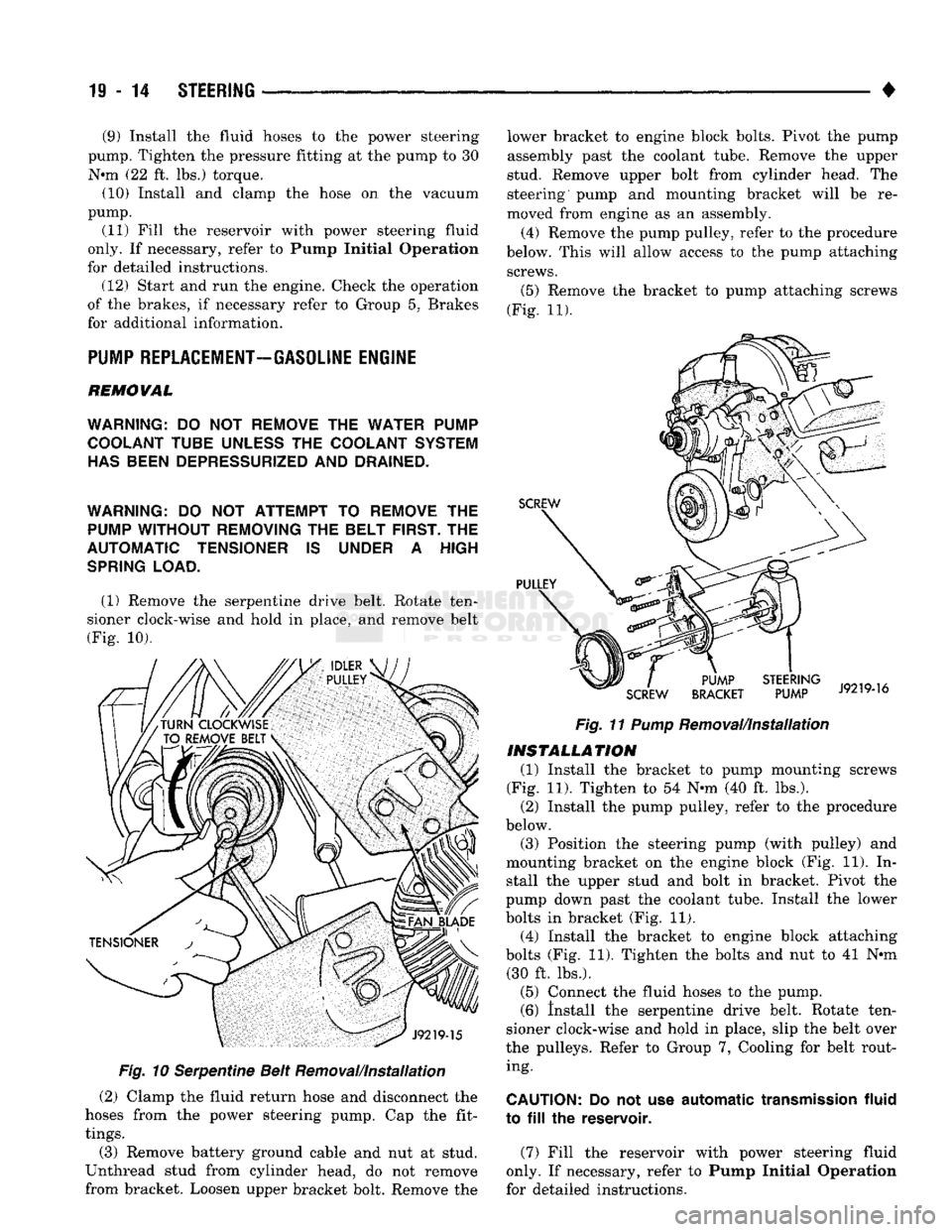
(1) Remove the serpentine drive belt. Rotate ten
sioner clock-wise and hold in place, and remove belt
(Fig. 10).
Fig.
10 Serpentine Belt Removal/Installation
(2) Clamp the fluid return hose and disconnect the
hoses from the power steering pump. Cap the fit
tings.
(3) Remove battery ground cable and nut at stud.
Unthread stud from cylinder head, do not remove
from bracket. Loosen upper bracket bolt. Remove the lower bracket to engine block bolts. Pivot the pump
assembly past the coolant tube. Remove the upper
stud. Remove upper bolt from cylinder head. The
steering pump and mounting bracket will be re
moved from engine as an assembly.
(4) Remove the pump pulley, refer to the procedure
below. This will allow access to the pump attaching screws.
(5)
Remove the bracket to pump attaching screws
(Fig. 11).
Fig.
11
Pump
Removal/Installation
INSTALLATION
(1) Install the bracket to pump mounting screws
(Fig. 11). Tighten to 54 N-m (40 ft. lbs.). (2) Install the pump pulley, refer to the procedure
below.
(3) Position the steering pump (with pulley) and
mounting bracket on the engine block (Fig. 11). In stall the upper stud and bolt in bracket. Pivot the
pump down past the coolant tube. Install the lower
bolts in bracket (Fig. 11). (4) Install the bracket to engine block attaching
bolts (Fig. 11). Tighten the bolts and nut to 41 N*m (30 ft. lbs.).
(5) Connect the fluid hoses to the pump. (6) Install the serpentine drive belt. Rotate ten
sioner clock-wise and hold in place, slip the belt over
the pulleys. Refer to Group 7, Cooling for belt rout ing.
CAUTION:
Do not use
automatic
transmission
fluid
to
fill the
reservoir.
(7) Fill the reservoir with power steering fluid
only. If necessary, refer to Pump Initial Operation
for detailed instructions.
Page 1086 of 1502
•
AUTOMATIC TRANSiISSiOi-32RH/38RH/37RH/42RH/4eRH
21 - 81 AUTOMATIC TRANSMISSION DIAGNOSIS AND TESTING
INDEX
page
Air Testing Clutch
and
Band Operation
91
Analyzing
the
Road Test
87
Converter Housing Fluid Leak Diagnosis
.......
92
Converter
Stall
Test
90
Diagnosis
Charts
and
Hydraulic Flow Diagrams
. . 95
Fluid Contamination
86
Fluid Level
and
Condition
85
GENERAL
INFORMATION
The diagnosis
and
testing information
in
this sec
tion applies
to
three
and
four speed models alike.
Di
agnosis
and
test procedures apply
to all
models
except where indicated. Diagnosis information that
only applies
to
42RH/46RH models
is
noted.
Automatic transmission problems
can be a
result
of
poor engine performance, incorrect fluid level, incor
rect linkage adjustment, band
or
hydraulic control
pressure adjustments, hydraulic system malfunctions
or electrical/mechanical component malfunctions.
Begin diagnosis
by
checking
the
easily accessible
items such
as:
fluid level
and
condition, linkage
ad
justments
and
electrical connections
on
4-speed mod
els.
A
road test will determine
if
further diagnosis
is
necessary. Procedures outlined
in
this section should
be
per
formed
in the
following sequence
to
realize
the
most accurate results:
• Preliminary diagnosis
• Fluid Level
and
condition • Linkage Adjustment
• Road test
• Hydraulic pressure test • Stall test
•
Air
pressure tests
• Leak Tests
• Analyze test results
and
consult diagnosis charts
PRELIMINARY
DIAGNOSIS
Two basic procedures
are
required.
One
procedure
for vehicles that
are
driveable
and an
alternate pro cedure
for
disabled vehicles (will
not
back
up or
move forward).
Vehicle
Is
Driveable
(1) Check fluid level
and
condition.
(2) Adjust throttle
and
gearshift linkage
if
com
plaint
was
based
on
delayed, erratic,
or
harsh shifts.
(3)
On
4-speed models, check electrical connections
at dash switch
and
transmission case. Turn control
switch
to ON
position before proceeding. (4) Road test
and
note transmission operating
characteristics.
page
Gearshift Linkage
87
General
Information
85
Hydraulic Pressure Test
88
Overdrive Fourth Gear
Electrical
Controls
......
86
Preliminary Diagnosis
85
Road
Test
87
Throttle
Valve Cable
86
(a)
If
acceleration
is
sluggish,
or if
abnormal
throttle opening
is
needed
to
maintain normal speeds with
a
properly tuned engine, perform
a
stall test
to
check converter clutch operation. (b)
On
42RH/46RH,
if
fourth gear upshift does
not occur, check overdrive solenoid
and
switch wir ing
for
opens, shorts, grounds.
(c)
If
slippage
and
engine flare
is
noted, perform
hydraulic pressure test
and air
pressure test
to
check clutch-band-governor operation.
Vehicle
Is
Disabled
(1) Check fluid level
and
condition.
(2) Check
for
broken, disconnected throttle link
age.
(3) Check
for
cracked, leaking cooler lines,
or
loose, missing pressure port plugs.
(4) Raise vehicle, start engine, shift transmission
into gear
and
note following:
(a)
If
propeller shafts turn
but
wheels
do not,
problem
is
with differential
or
axle shafts. (b)
If
propeller shafts
do not
turn
and
transmis
sion
is
noisy, stop engine. Remove
oil pan, and
check
for
debris.
If pan is
clear, remove transmis
sion
and
check
for
damaged drive plate, converter,
oil pump
or
input shaft.
(c)
If
propeller shafts
do not
turn
and
transmis
sion
is not
noisy, perform hydraulic pressure test
to
deter
mine
if
problem
is a
hydraulic
or
mechanical.
FLUID LEVEL AND CONDITION
(1) Place vehicle
on
level surface. This
is
impor
tant
for an
accurate reading. (2)
Do not
check level until fluid
is at
normal
op
erating temperature
of
approximately 82°C (180°F).
This
is
necessary
to
avoid false readings which could
produce under
or
over fill condition, (3) Fully apply parking brakes.
(4) Start
and run
engine
at
curb idle speed. Then
shift transmission through
all
gear ranges
and
back
to Neutral. (5) Clean
top of
filler tube
and
dipstick
to
keep dirt
out
of
tube.
Page 1090 of 1502
•
AUTOMATIC
TRANSMISSION—32RH/36RH/37RH/42RH/46RH
21 - 89
Fig.
5
Pressure
Test Port
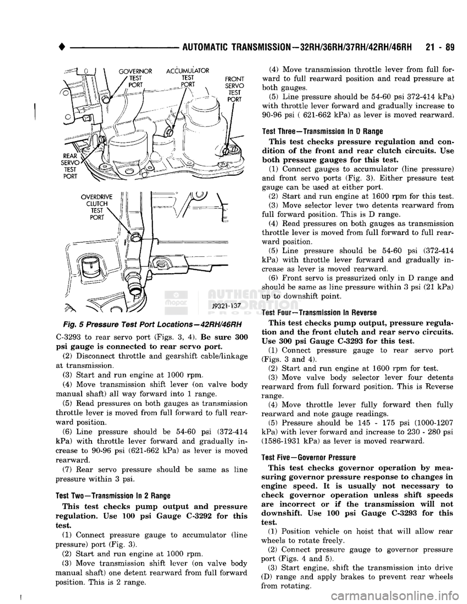
Locations—42RH/46RH
C-3293 to rear servo port (Figs. 3, 4). Be sure 300
psi gauge is connected to rear servo port.
(2) Disconnect throttle and gearshift cable/linkage
at transmission. (3) Start and run engine at 1000 rpm.
(4) Move transmission shift lever (on valve body
manual shaft) all way forward into 1 range.
(5) Read pressures on both gauges as transmission
throttle lever is moved from full forward to full rear
ward position.
(6) Line pressure should be 54-60 psi (372-414
kPa) with throttle lever forward and gradually in
crease to 90-96 psi (621-662 kPa) as lever is moved
rearward.
(7) Rear servo pressure should be same as line
pressure within 3 psi.
Test
Two—Transmission
In 2
Range
This test checks pump output and pressure
regulation. Use 100 psi Gauge C-3292 for this test. (1) Connect pressure gauge to accumulator (line
pressure) port (Fig. 3).
(2) Start and run engine at 1000 rpm.
(3) Move transmission shift lever (on valve body
manual shaft) one detent rearward from full forward
position. This is 2 range. (4) Move transmission throttle lever from full for
ward to full rearward position and read pressure at
both gauges.
(5) Line pressure should be 54-60 psi 372-414 kPa)
with throttle lever forward and gradually increase to 90-96 psi ( 621-662 kPa) as lever is moved rearward.
Test
Three—Transmission
In D
Range
This test checks pressure regulation and con
dition of the front and rear clutch circuits. Use
both pressure gauges for this test.
(1) Connect gauges to accumulator (line pressure)
and front servo ports (Fig. 3). Either pressure test
gauge can be used at either port.
(2) Start and run engine at 1600 rpm for this test.
(3) Move selector lever two detents rearward from
full forward position. This is D range.
(4) Read pressures on both gauges as transmission
throttle lever is moved from full forward to full rear
ward position.
(5) Line pressure should be 54-60 psi (372-414
kPa) with throttle lever forward and gradually in crease as lever is moved rearward. (6) Front servo is pressurized only in D range and
should be same as line pressure within 3 psi (21 kPa)
up to downshift point.
Test
Four—Transmission
In
Reverse
This test checks pump output, pressure regula
tion and the front clutch and rear servo circuits.
Use 300 psi Gauge C-3293 for this test.
(1) Connect pressure gauge to rear servo port
(Figs.
3 and 4). (2) Start and run engine at 1600 rpm for test. (3) Move valve body selector lever four detents
rearward from full forward position. This is Reverse
range.
(4) Move throttle lever fully forward then fully
rearward and note gauge readings.
(5) Pressure should be 145 - 175 psi (1000-1207
kPa) with lever forward and increase to 230 - 280 psi (1586-1931 kPa) as lever is moved rearward.
Test
Five—Governor
Pressure
This test checks governor operation by mea
suring governor pressure response to changes in
engine speed. It is usually not necessary to check governor operation unless shift speeds
are incorrect or if the transmission will not
downshift. Use 100 psi Gauge C-3293 for this
test.
(1) Position vehicle on hoist that will allow rear
wheels to rotate freely.
(2) Connect pressure gauge to governor pressure
port (Figs. 4 and 5). (3) Start engine, shift the transmission into drive
(D) range and apply brakes to prevent rear wheels
from rotating.
Page 1091 of 1502
21 - 90
AUTOMATIC
TRANSMISSION—32RH/36RH/37RH/42RH/46RH
• (4) Note pressure with engine at curb idle speed
and rear wheels stopped. Pressure should be zero to 1-1/2 psi maximum. If pressure exceeds this figure,
governor valve or weights are sticking open.
(5) Slowly increase engine rpm and observe speed
ometer and pressure test gauge. Governor pressure should increase in proportion to indicated vehicle
speed (or approximately 1 psi for every 1 mph).
(6) Pressure rise should be smooth and drop back
to 0 to 1-1/2 psi when wheels are braked to a stop and engine returns to curb idle speed.
(7) Compare results of the pressure tests with the
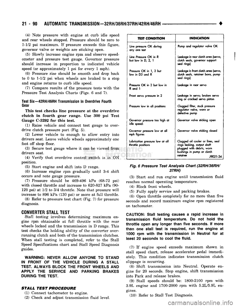
Pressure Test Analysis Charts (Figs. 6 and 7).
Test
Six—42RH/46RH
Transmission
In Overdrive Fourth
Gear
This test checks line pressure at the overdrive
clutch in fourth gear range. Use 300 psi Test
Gauge C-3292 for this test.
(1) Raise vehicle and connect test gauge to over
drive clutch pressure port (Fig. 5). (2) Lower vehicle to enough to allow entry into
drivers seat. Leave vehicle wheels approximately one
foot off shop floor.
(3) Secure test gauge where it can be viewed from
drivers seat.
(4) Verify that overdrive control switch is in ON
position. (5) Start engine and shift into D range.
(6) Increase engine rpm gradually until 3-4 shift
occurs and note gauge pressure. (7) Pressure should be 469-496 kPa (68-72 psi)
with closed throttle and increase to 620-827 kPa (90- 120 psi) at 1/2 to 3/4 throttle. Note that pressure will
increase to 896 kPa (130 psi) or more at full throttle. (8) Refer to pressure test chart (Fig. 7) for pressure
diagnosis.
CONVERTER
STALL
TEST
Stall testing involves determining maximum en
gine rpm obtainable at full throttle with the rear
wheels locked and the transmission in D range. This
test checks the holding ability of the converter over
running clutch and both of the transmission clutches. When stall testing is completed, refer to the Stall
Speed Specifications chart and Stall Speed Diagnosis
guides.
WARNING:
NEVER
ALLOW
ANYONE
TO
STAND
IN
FRONT
OF THE
VEHICLE
DURING
A
STALL
TEST.
ALWAYS
BLOCK
THE
FRONT
WHEELS
AND
APPLY
THE
SERVICE
AND
PARKING
BRAKES
DURING
THE
TEST.
STALL
TEST
PROCEDURE
(1) Connect tachometer to engine.
(2) Check and adjust transmission fluid level.
1EST
CONDITION
INDICATION
Line
pressure
OK during
any
one test
Pump
and regulator valve OK
Line
Pressure
OK in R
but low in D, 2, 1
Leakage
in
rear
dutch area
(servo,
dutch
seals,
governor
support
seal
rings)
Pressure
OK in 1, 2 but
low
in D3 and R
Leakage
in
front
dutch area
(servo,
dutch
seals,
retainer
bore,
pump
seal
rings)
Pressure
OK in 2 but low in
R
and 1
Leakage
in
rear
servo
Front
servo
pressure
in 2
Leakage
in
servo;
broken
servo
ring
or
cracked
servo
piston
Pressure
low in all
positions
Cogged
filter,
stuck
pressure
regulator valve, worn or
defective
pump
Governor
pressure
too
high
at idle
speed:
Governor
valve
sticking
open
Governor
pressure
low at all
mph
figures
Governor
valve
sticking
dosed
Lubrication
pressure
low at all
throttle
positions
Clogged
oil cooler or
lines,
seal
rings
leaking,
output shaft
plugged
with
debris,
worn
bushings
in
pump
or dutch
retainer
J9021-34
Fig.
6
Pressure
Test
Analysis
Chart (32RH/36RH/
37RH)
(3) Start and run engine until transmission fluid
reaches normal operating temperature. (4) Block front wheels.
(5) Fully apply service and parking brakes.
(6) Open throttle completely for no more than five
seconds and record maximum engine rpm registered
on tachometer.
CAUTION:
Stall testing
causes
a rapid increase in
transmission
fluid
temperature. Do not
hold
the
throttle
open
any
longer
than
five
seconds.
If more
than one stall test is required, run the engine at 1000 rpm
with
the
transmission
in Neutral for at
least
20
seconds
to
cool
the fluid.
(7) If engine speed exceeds maximum shown in
stall speed chart, release accelerator pedal immedi
ately. This condition indicates transmission clutch
slippage is occurring.
(8) Shift transmission into Neutral. Operate en
gine for 20 seconds. Stop engine, shift transmission
into Park and release brakes.
(9) Stall speeds should be: 1800-2100 rpm with
3.9L engine and 1700-2000 rpm with 5.2L/5.9L en
gines.
(10) Refer to Stall Test Diagnosis.
Page 1131 of 1502
21
-
130
IN-VEHICLE
SERVICE-~32RH/36RH/37RH/42RH/4iRH
•
IN-VEHICLE
SERVICE-32RH/36RH/37RH/42RH/46RH
INDEX
page
Aluminum Thread Repair
141
Checking
Fluid
Level
130
Extension Housing Bushing
and
Output
Shaft
Bearing
Service-32RH/36RH/37RH
... .
135
Extension Housing Yoke Seal Replacement
....
135
Fluid
and Filter
Change
130
Front
Band
Adjustment
133
Gearshift Linkage
Adjustment
130
Governor
and
Park Gear Service—
32RH/36RH/37RH
137
Governor
and
Park Lock Service—42RH/46RH
.
138
CHECKING
FLUID LEVEL
(1) Position vehicle
on
level surface. This
is ex
tremely important
for
accurate check.
(2)
Apply parking brakes
and run
engine
at
curb
idle speed.
(3)
Shift transmission momentarily into
all
gear
ranges. Then shift back
to
Neutral.
(4)
Clean
top of
filler tube
and
dipstick
(to
avoid
dirt entry)
and
check fluid level. Correct level
is as
follows:
(5)
Be
sure fluid
is at
normal operating tempera
ture (180°F). Correct level
is
between "Maximum Level
Hot"
and
"Add"
marks (crosshatched area)
on
dipstick. (6)
If
fluid level
is
low,
add
only enough fluid
to
correct level.
CAUTION:
Do not
overfill
the
transmission. Overfilling
will
force fluid
out
the
pump vent which
can
be
mistaken
for
a
pump seal leak. Overfilling
will
also
cause
fluid aeration
and foaming
when
the
excess
fluid
is
picked
up
and
churned
by
the
gear train. Aeration
will
reduce fluid
life
significantly.
FLUID
AND
FILTER
CHANGE
Normal Change
Interval
The fluid
and
filter should
be
changed
(and the
bands adjusted)
at
recommended maintenance inter
vals.
Or
whenever
the
transmission
has
been disassembled
for
any
reason.
Recommended Fluid
The recommended
(and
preferred) fluid
for
Chrysler automatic transmissions
is
Mopar
ATF
Plus,
type
7176.
Use
Mopar Dexron
II
only when
ATF Plus
is not
readily available.
page
Park Lock
Service-32RH/36RH/37RH
. 138
Park/Neutral Position Switch
134
Rear
Band
Adjustment
133
Speedometer Service
134
Transmission Cooler Service
140
Transmission
Throttle
Cable
Adjustment-
Cummins Diesel Engine
132
Transmission
Throttle
Cable
Adjustment-
Gas
Engines
131
Valve Body
Control
Pressure Adjustments
.....
140
Valve Body Service
138
Severe Usage Change
Interval
Under severe usage,
the
fluid
and
filter should
be
changed
and the
bands adjusted
at
12,000 mile (19,000
km)
intervals.
Severe usage
is
defined
as:
• More than half
of
vehicle operation occurs
in
heavy city traffic during
hot
weather
at
ambient
temperatures above
90°
F.
• Vehicle
is
used
for
Taxi, Police, Limousine,
or
sim
ilar commercial operations.
• Vehicle
is
used
for
trailer/boat towing
or
heavy
load hauling. When
the
factory fluid
is
drained, refill
the
trans
mission with Mopar
ATF
Plus, type
7176
fluid.
Mo
par Dexron
II
can
be
used
if
ATF
Plus
is
not
readily available.
FLUID
AND
FILTER
REPLACEMENT
PROCEDURE
(1) Raise vehicle, remove
oil pan
and
drain fluid.
(2) Remove filter screws
and
remove filter.
(3) Position
new
filter
on
valve body
and
install fil
ter screws finger tight. (4) Tighten filter screws
to 4
N*m (35
in.
lbs.)
with
torque wrench.
(5) Position
new
gasket
on oil pan
and
install
pan
on transmission. Tighten
pan
bolts
to 17
N»m
(150
in.
lbs.)
torque. (6) Lower vehicle
and
refill transmission with rec
ommended fluid.
GEARSHIFT LINKAGE ADJUSTMENT
Check linkage adjustment
by
starting
the
engine
in Park
and
Neutral. Adjustment
is
OK
if
the
engine starts only
in
park
and Neutral. Adjustment
is
incorrect
if
the
engine starts
in one
but
not
both positions. If
the
engine starts
in
any
position other than Park
or Neutral,
or if
the
engine will
not
start
at
all,
the
park/neutral position switch
may
be
faulty.