Page 905 of 1216
AUTOMATIC TRANSAXLE - Service Adjustment Procedures21-21109A0146
OQMOO45
control lever
control lever
5 mm
Section A-A
(2 in.)Manual
controllever
Switch body
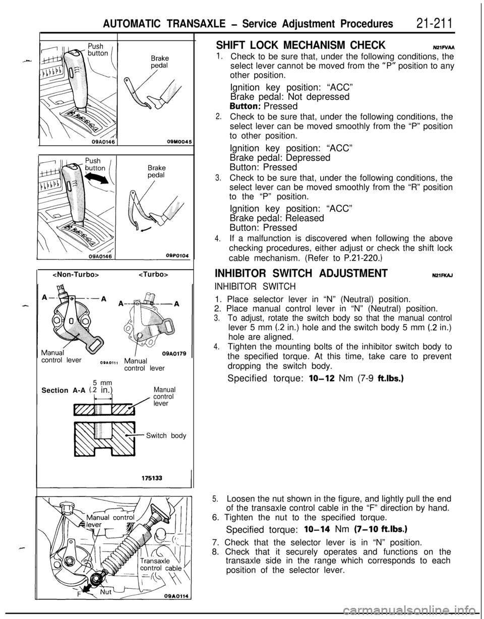
SHIFT LOCK MECHANISM CHECKN21FVAA
1.
2.
3.
4.Check to be sure that, under the following conditions, the
select lever cannot be moved from the
“P” position to any
other position.
Ignition key position: “ACC”
Brake pedal: Not depressedButton: Pressed
Check to be sure that, under the following conditions, the
select lever can be moved smoothly from the “P” position
to other position.
Ignition key position: “ACC”
Brake pedal: Depressed
Button: Pressed
Check to be sure that, under the following conditions, the
select lever can be moved smoothly from the “R” position
to the “P” position.
Ignition key position: “ACC”
Brake pedal: Released
Button: Pressed
If a malfunction is discovered when following the above
checking procedures, either adjust or check the shift lock
cable mechanism. (Refer to
P.21-220.)
INHIBITOR SWITCH ADJUSTMENTNZlFKAJ
INHIBITOR SWITCH1. Place selector lever in “N” (Neutral) position.
2. Place manual control lever in “N” (Neutral) position.
3.To adjust, rotate the switch body so that the manual controllever 5 mm
(2 in.) hole and the switch body 5 mm (.2 in.)
hole are aligned.
4.Tighten the mounting bolts of the inhibitor switch body to
the specified torque. At this time, take care to prevent
dropping the switch body.
Specified torque:
lo-12 Nm (7-9 ftlbs.)
5.Loosen the nut shown in the figure, and lightly pull the end
of the transaxle control cable in the “F” direction by hand.
6. Tighten the nut to the specified torque.
Specified torque:
IO-14 Nm (7-10 ftlbs.)7. Check that the selector lever is in “N” position.
8. Check that it securely operates and functions on the
transaxle side in the range which corresponds to each
position of the selector lever.
Page 906 of 1216
21-212AUTOMATIC TRANSAXLE -Service Adiustment Procedures
1750464
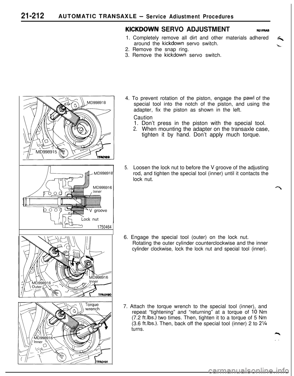
KICKOOWN SERVO ADJUSTMENTNZlFRAB1. Completely remove all dirt and other materials adhered
G+around the kickdown servo switch.
-i-s-2. Remove the snap ring.
3. Remove the kickdown servo switch.
4. To prevent rotation of the piston, engage the
pawl of the
special tool into the notch of the piston, and using the
adapter, fix the piston as shown in the left.
Caution1. Don’t press in the piston with the special tool.
2.When mounting the adapter on the transaxle case,
tighten it by hand. Don’t apply much torque.
5.Loosen the lock nut to before the V groove of the adjusting
rod, and tighten the special tool (inner) until it contacts the
lock nut.
6. Engage the special tool (outer) on the lock nut.
Rotating the outer cylinder counterclockwise and the inner
cylinder clockwise, lock the lock nut and special tool (inner).7. Attach the torque wrench to the special tool (inner), and
repeat “tightening” and “returning” at a torque of
IO Nm
(7.2
ft.lbs.) two times. Then, tighten it to a torque of 5 Nm
(3.6
ftlbs.). Then, back off the special tool (inner) 2 to 2%
turns.*
. .
Page 907 of 1216
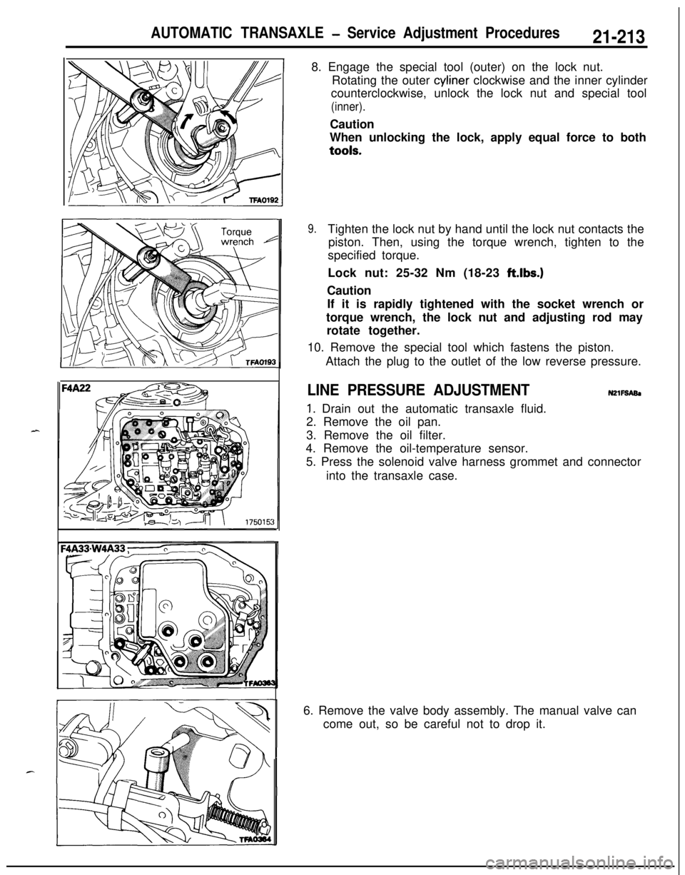
AUTOMATIC TRANSAXLE - Service Adjustment Procedures21-2138. Engage the special tool (outer) on the lock nut.
Rotating the outer cyliner clockwise and the inner cylinder
counterclockwise, unlock the lock nut and special tool
(inner).Caution
When unlocking the lock, apply equal force to bothtools.
9.Tighten the lock nut by hand until the lock nut contacts the
piston. Then, using the torque wrench, tighten to the
specified torque.
Lock nut: 25-32 Nm (18-23 ft.lbs.)
Caution
If it is rapidly tightened with the socket wrench or
torque wrench, the lock nut and adjusting rod may
rotate together.
10. Remove the special tool which fastens the piston.
Attach the plug to the outlet of the low reverse pressure.
LINE PRESSURE ADJUSTMENTN2lFSABl
1. Drain out the automatic transaxle fluid.
2. Remove the oil pan.
3. Remove the oil filter.
4. Remove the oil-temperature sensor.
5. Press the solenoid valve harness grommet and connector
into the transaxle case.
6. Remove the valve body assembly. The manual valve can
come out, so be careful not to drop it.
Page 908 of 1216
21-214AUTOMATIC TRANSAXLE - Service Adjustment Procedures
'50157
F4
1
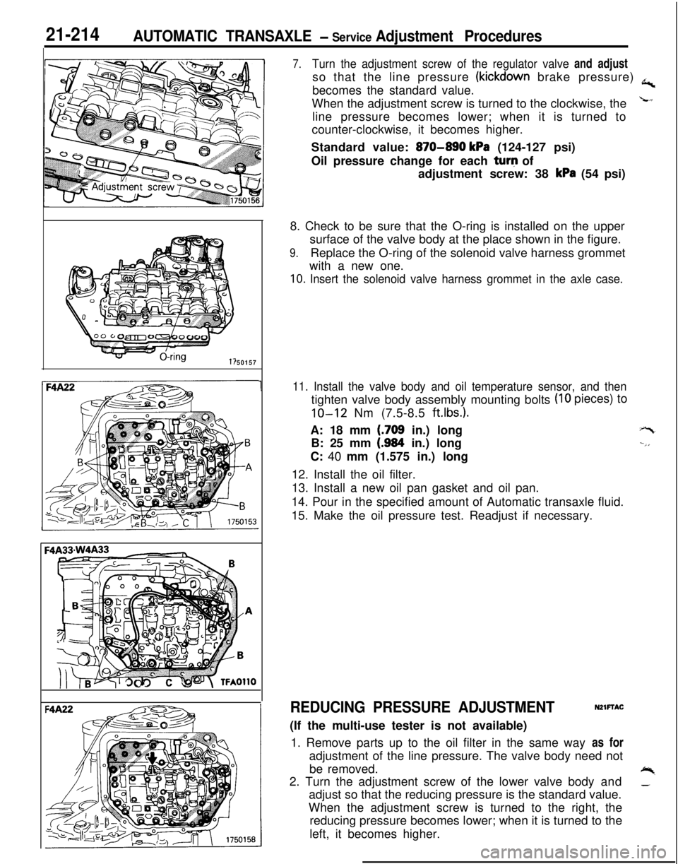
7.Turn the adjustment screw of the regulator valve and adjustso that the line pressure
(kickdown brake pressure) a,becomes the standard value.
When the adjustment screw is turned to the clockwise, the
Lline pressure becomes lower; when it is turned to
counter-clockwise, it becomes higher.
Standard value:
870-890 kPa (124-127 psi)
Oil pressure change for each turq of
adjustment screw: 38
kPa (54 psi)
8. Check to be sure that the O-ring is installed on the upper
surface of the valve body at the place shown in the figure.
9.Replace the O-ring of the solenoid valve harness grommet
with a new one.
10. Insert the solenoid valve harness grommet in the axle case.
11. Install the valve body and oil temperature sensor, and then
(IO pieces) to
tighten valve body assembly mounting bolts
IO-12 Nm (7.5-8.5 ft.lbs.).A: 18 mm
(.709 in.) long
B: 25 mm
(.984 in.) long
C: 40 mm (1.575 in.) long
12. Install the oil filter.
13. Install a new oil pan gasket and oil pan.
14. Pour in the specified amount of Automatic transaxle fluid.
15. Make the oil pressure test. Readjust if necessary.
+-t
--,,
REDUCING PRESSURE ADJUSTMENTNZlFTAC(If the multi-use tester is not available)
1. Remove parts up to the oil filter in the same way as for
adjustment of the line pressure. The valve body need not
be removed.
+%2. Turn the adjustment screw of the lower valve body and_adjust so that the reducing pressure is the standard value.
When the adjustment screw is turned to the right, the
reducing pressure becomes lower; when it is turned to the
left, it becomes higher.
Page 911 of 1216
AUTOMATIC TRANSAXLE - Transaxle Control21-217
TRANSAXLE CONTROL
dl_i REMOVAL AND INSTALLATIONNZlub-
-.
lo-14 Nm7-10 ft.lbs.
i284-6
Nm
y-14 Nm7-10 ft.lbs.
Transaxle control cable and selector lever
assembly removal steps
1. Plug2. Side cover (B)3. Power (PWR)/Economy (ECO) switch
4. Side cover(B)
5. Cover(B)
6. Cup holder7. Carpet
8.
EZrreTstion of floor console wiring
9. Guide ring
IO. Shoulder belt 11. Floor console
17. Snap pin18. Key interlock cable (selector lever
assembly side)
23.
S$i; lock cable (selector lever assembly
26. Snap pin27. Clip
28. Adjusting nut
l 4 29. Clip++ 30. Transaxle control cable31. Selector lever assembly
zykeverse the removal procedures to reinstall.(2) l + : Refer to “Service Points of Installation”
Page 912 of 1216
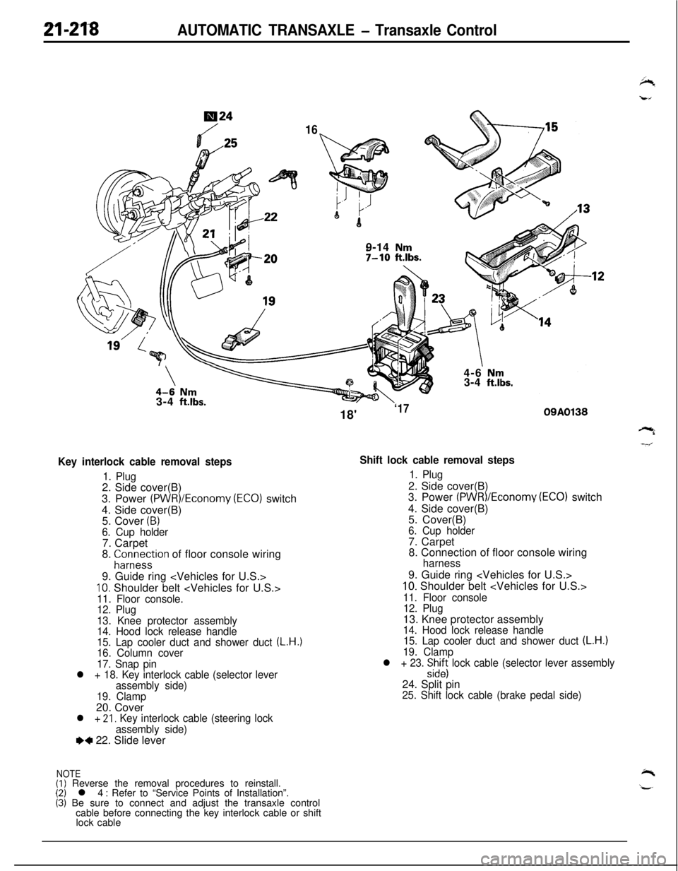
2l-218AUTOMATIC TRANSAXLE - Transaxle Control
724
169-14
Nm7-10 ftlbs.7
\\4-6 Nm3-4 ft.lbs.3-4
ft.lbs.
Key interlock cable removal steps
1. Plug2. Side cover(B)
3. Power
(PWR)/Economy (ECO) switch
4. Side cover(B)
5. Cover
(B)6. Cup holder7. Carpet
8.
;ir;eystion of floor console wiring
9. Guide ring
10. Shoulder belt 11. Floor console.
12. Plug
13. Knee protector assembly
14. Hood lock release handle
15. Lap cooler duct and shower duct
(L.H.)16. Column cover
17. Snap pin
l + 18. Key interlock cable (selector lever
assembly side)
19. Clamp20. Cover
l + 21, Key interlock cable (steering lock
assembly side)
e+ 22. Slide lever
NOTE(I) Reverse the removal procedures to reinstall.(2) l 4 : Refer to “Service Points of Installation”.(3) Be sure to connect and adjust the transaxle control
cable before connecting the key interlock cable or shift
lock cable18'
‘1709A0138
Shift lock cable removal steps
1. Plug2. Side cover(B)
3. Power
(PWR)/Economv (EC01 switch
4. Side cover(B)
’5. Cover(B)
6. Cup holder7. Carpet
8. Connection of floor console wiring
harness9. Guide ring
10. Shoulder belt
11. Floor console
12. Plug13. Knee protector assembly
14. Hood lock release handle
15. Lap cooler duct and shower duct (L.H.)19. Clamp
l + 23. :izs lock cable (selector lever assembly24. Split pin
25. Shift lock cable (brake pedal side)
Page 914 of 1216

AUTOMATIC TRANSAXLE - Transaxle Control
:lemotJnt
\\ \09R0058
09AO143
/’
\
’ CoverCoverKey interlock cableOSA0125
OSAO12629. INSTALLATION OF CLIP
When connecting the control cable to the transaxle mount
,-bracket, install the clip until it contacts the control cable, in
the position shown in the figure.
,”l ADJUSTMENT OF TRANSAXLE CONTROL CABLE
Refer to the section concerning adjustment of the inhibitor
switch. (Refer to P.21-211.)
23. INSTALLATION OF SHIFT LOCK CABLE (SELECT LEVERASSEMBLY SIDE)
(1) Move the select lever to the “R” position.
(2) Clamp the shift lock cable.
(3) Connect the shift lock cable to the select lever
assembly, and temporarily tighten the nut.
(4) Slide the shift lock cable so that the distance between
the select lever assembly’s detent pin and the end of
the shift lock cable is the standard value, and then
tighten the nut at the specified torque.
Standard value (A):
l-4 mm (.04-.I5 in.)
(5) After connecting the shift lock cable, check the shift
lock mechanism. (Refer to P.21-211.)
22. INSTALLATION OF THE SLIDE LEVERI21. KEY INTER-
LOCK CABLE (STEERING LOCK ASSEMBLY SIDE)
(1) With the ignition key either at the “LOCK” position or
removed, install the slide lever to the key cylinder.
(2) Connect, as shown in the figure, the key interlock cable
to the slide lever and the key cylinder.
(3) Apply a light coating of multipurpose grease where
shown in the figure.
Grease: MOPAR Multi-mileage Lubricant Part
No. 2525035 or equivalent
(4) Install the key interlock cable.
18. INSTALLATION OF KEY INTERLOCK CABLE (SELECT
LEVER ASSEMBLY SIDE)
(1) Move the select lever to the “P” postion.(2) Connect the key interlock cable to the select lever
assembly’s lock cam. Be sure that the spring installed
to the key interlock cable is as shown in the figure.
*(3) While gently pressing the lock cam in the
F direction,-tighten the nut to secure the key interlock cable.
(4) After connecting the key interlock cable, check the key
interlock mechanism. (Refer to ‘P.21-210.)
Page 915 of 1216
AUTOMATIC TRANSAXLE - Transaxle Control
DISASSEMBLY AND REASSEMBLY (SELECT LEVER ASSEMBLY)N210E--2.0 Nm or more
1.4
ft.lbs. or more
2.0 Nm or more
1.4
ft.lbs. or more
/1.0-2.0 Nm0.7-1.4 ft.lbs.14-20 Nm
lo-14 ft.lbs.
Disassembly steps
4+1. Overdrive control switch connector2.Cover3.Selector knob::4.Overdrive controlswitchbutton
5. Overdrive control switch
6.Pinl * 7. Pushbutton
ea8.Spring9.Indicator panel10.Slider11. indicator panel lower
12.Socket assembly
OSA0135
*413.Sleeve14.Lever assemblyI)+15.Bushing
16.Pipe17.Split pinl * 18. Lock cam19.Bracket assembly
NOTE(I) Reverse the disassembly procedures to reassemble.(2) ++ : Refer to “Service Points of Disassembly”.(3) l + : Refer to “Service Points of Reassembly”.
Sciewdriver
SERVICE POINTS OF DISASSEMBLYN21OFAC1. REMOVAL OF OVERDRIVE CONTROL SWITCH CON-
NECTORDisconnect the overdrive control switch connector and
then remove the terminal from the overdrive control
switch connector.