1991 MITSUBISHI ECLIPSE seat adjustment
[x] Cancel search: seat adjustmentPage 62 of 1216

2-14FRONT SUSPENSION - Hub and Knuckle
llR0032
llK012SERVICE POINTS OF REASSEMBLY
NOZIHAN5. INSTALLATION OF WHEEL BEARING
A(1) Fill the wheel bearing with multipurpose grease.
-(2) Apply a thin coating of multipurpose grease to the
knuckle and bearing contact surfaces.
Grease: MOPAR Multi-mileage Lubricant
Part No.2525035 or equivalent
(3) With the wheel bearing inner race removed, press-in
the bearing by using the special tools.
(4) Install the wheel bearing inner race to the wheel
bearing.4. INSTALLATION OF OIL SEAL (HUB SIDE)
(1) Drive the oil seal (hub side) into the knuckle by using
the
soecial tools until it is flush with the knuckle end
surface.A(2) Apply multipurpose grease to the lip of the oil seal and
to the surfaces of the oil seal which contact the front
hub.Grease: MOPAR Multi-mileage Lubricant
Part No.2525035 or equivalent
1. INSTALLATION OF FRONT HUB
(1) Use the special tool to mount the front hub assembly
onto the knuckle.
(2) Tighten the nut of the special tool to 200-260 Nm
(144-188
ft.lbs.).(3) Rotate the front hub assembly in order to seat the
bearing.l ADJUSTMENT OF WHEEL BEARING STARTING
TORQUE(1) Measure the wheel bearing starting torque (hub
starting torque) by using the special tools.
Limit: 1.8 Nm (16
in.lbs.) or lessic
‘-NOTEThe starting torque must be within the limit and, in
addition, the bearing must not feel rough when
rotated.
Page 130 of 1216

3-28REAR AXLE - Differential Carrier
Y223
MB990031(4) Position the special tool in the side bearing seat of the
gear carrier, and then select a drive pinion rear shim of athickness which corresponds to the gap between the
special tools.
NOTE
Clean the side bearing seat thoroughly. When position-
ing the special tool, be sure that the cut-out sections ofthe special tool are in the position shown in the
illustration, and also confirm that the special tool is in
close contact with the side bearing seat.
When selecting the drive pinion rear shims, keep the
number of shims to a minimum.
(5) Fit the selected drive pinion rear shim(s) to the drive
pinion, and press-fit the drive pinion rear bearing inner
race by using the special tool.
. ADJUSTMENT OF DRIVE PINION PRELOAD
Adjust the drive pinion turning torque by using the following
procedures:
(1) Fit the drive pinion front shim(s) between the drive
pinion spacer and the drive pinion front bearing inner
race.
(2) Tighten the companion flange to the specified torque byusing the special tools.
NOTEDo not install the oil seal.
(3) Measure the drive pinion turning torque (without the oil
seal) by using the special tools.
Standard value:
21
.;c
1 New
New/reused Oil application
0.4-0.5 (3-4)
(4) If the drive pinion turning torque is not within the range
of the standard value, adjust the turning torque by
replacing the drive pinion front shim(s) or the drive
pinion spacer.
NOTEWhen selecting the drive pinion front shims, if the
number of shims is large, reduce the number of shims
to a minimum by selecting the drive pinion spacers.
Page 297 of 1216

ENGINE - SDecificationsItems
TensionN (Ibs.)
Inspection
New belt
Used belt
For power steering pump
Deflectionmm (in.)
Inspection
Timing belt tensionmm (in.)Standard Value
250-500 (55-l 10)
470-570 (104- 126)
320-400 (71-88)
6.0-9.0 (.236-.354)14
(.55)NOTE
O.D.: Outer Diameter
I.D.: Inner Diameter
OS.: Oversize Diameter
U.S.: Undersize Diameter<2.0L DOHC Engine>
-ItemsStandard ValueLimit
Engine adjustments
Engine compression pressurekPa (psi)
(Turbo)
Engine compression pressure difference
between each cylinderkPa (psi)
Intake manifold vacuum at idlemm Hg
(in.Hg)
Timing belt “B” tensionmm (in.)
-
-
-490 (19.3)
480 (18.9)
5-7
(.20-.28)Cylinder head
Overall heightmm (in.)132.0 (5.197)
Flatness of gasket surfacemm (in.)
Flatness of manifold mounting surfacemm (in.)
Oversize rework dimension of valve seat hole
mm (in.)
Intake0.3
(.012) 0,s.0.6 (0.24)
0,s.Exhaust 0.3
(.012) OS.
0.6
(.024) 0.S~ less than 0.05
(.0020)Less than 0.15
(.0059)
35.300-35.325(1.3898-1.3907)
35.600-35.625
(1.4016-l .4026)
33.300-33.325(1.3110-1.3120)
33.600-33.625
(1.3228- 1.3238)Limit
Min. 960 (137)
Min. 800 (114)
Max. 100 (14)
-0.2
(-,008)”*Limit must be -0.2
(- .008) combined
with amount of
grinding of cylinder
block gasket surface.
0.2
(.008)0.3
(.012)
Page 308 of 1216

9-24ENGINE - Service Adjustment Procedures
ENGINE 4.8L Engine>
SERVICE ADJUSTMENT PROCEDURES -
CHECKING COMPRESSION PRESSURENOSFFAI
(1) Before checking compression, ensure that engine oil, the
starter motor, and battery are all in good condition.
(2) Start the engine and wait until engine coolant temperature
has risen to
85-95°C (185-205°F).
(3) Stop the engine and pull the spark plug cables.
(4) Remove the spark plugs.
(5) Crank the engine to remove any foreign objects in the
cylinders.Caution
Cover the spark plug holes with shop towel, etc., in
order to keep expelled foreign objects from flying out,
and keep away from the holes. When measuring
compression with water, oil, or fuel having entered the
cylinder through a crack, etc., these will come flying
out of the spark plug hole hot and fast, so be sure to
take the proper precautions.
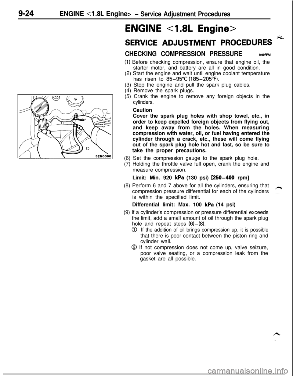
(6) Set the compression gauge to the spark plug hole.
(7) Holding the throttle valve full open, crank the engine and
measure compression.
Limit: Min. 920
kPa (130 psi) [250-400 rpm]
(8) Perform 6 and 7 above for all the cylinders, ensuring that
compression pressure differential for each of the cylinders
/Iis within the specified limit.
__Differential limit: Max. 100
kPa (14 psi)
(9) If a cylinder’s compression or pressure differential exceeds
the limit, add a small amount of oil through the spark plug
hole and repeat steps (6)-(8).
0If the addition of oil brings compression up, it is possiblethat there is poor contact between the piston ring and
cylinder wall.
@ If not compression does not come up, valve seizure,
poor valve seating, or a compression leak from the
gasket are all possible.
/y
-
Page 309 of 1216

ENGINE <1.8L Engine>- Service Adjustment Procedures9-25
MANIFOLD VACUUM INSPECTION(1) Before inspection and adjustment, put the vehicle
in=following state.
l Engine coolant temperature:
85-95°C (185-205°F)
l Lights, electric, cooling fan, and accessories: OFF
lTransaxle: Neutral
(N or P for vehicles with an automa-
tic transaxle)
l Steering wheel: Neutral position
(2) Check that the idling revolution speed is normal.
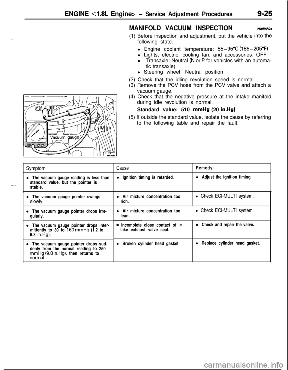
(3) Remove the PCV hose from the PCV valve and attach a
vacuum gauge.
(4) Check that the negative pressure at the intake manifold
during idle revolution is normal.
Standard value: 510 mmHg (20
in.Hg)(5) If outside the standard value, isolate the cause by referring
to the following table and repair the fault.
SymptomCauseRemedy
l The vacuum gauge reading is less thanl Ignition timing is retarded.l Adjust the ignition timing.
standard value, but the pointer is
-stable.
l The vacuum gauge pointer swingsl Air mixture concentration too
slowly.rich.
l Check ECI-MULTI system.l The vacuum gauge pointer drops irre-
gularly.
l The vacuum gauge pointer drops inter-
mittently to 30 to
160 mmHg (1.2 to
6.3 in.Hg).l The vacuum gauge pointer drops sud-
denly from the normal reading to 250rronnrt$,(9.8 rn.Hg), then returns tol Air mixture concentration too
lean.
l Check ECI-MULTI system.0 Incomplete close contact of in-
take exhaust valve seat.l Check and repair the valve.
l Broken cylinder head gasketl Replace cylinder head gasket.
Page 358 of 1216

9-74ENGINE <2.0L DOHC Engine>- Service Adjustment Procedures
ENGINE <2.0L DOHC Engine>
SERVICE ADJUSTMENT PROCEDURES pi
CHECKING COMPRESSION PRESSURENOSFFAH(1) Before checking compression, ensure that engine oil, the
starter motor, and battery are all in good condition.
(2) Start the engine and wait until engine coolant temperature
has risen to
85-95°C (185-205°F).
(3) Stop the engine and pull the spark plug cables.
(4) Remove the spark plugs.
(5) Crank the engine
to. remove any foreign objects in the
cylinders.
Caution
Cover the spark plug holes with shop towel, etc., in
order to keep expelled foreign objects from flying out,and keep away from the holes. When measuring
compression with water, oil, or fuel having entered the
cylinder through a crack, etc., these will come flying
out of the spark plug hole hot and fast, so be sure to
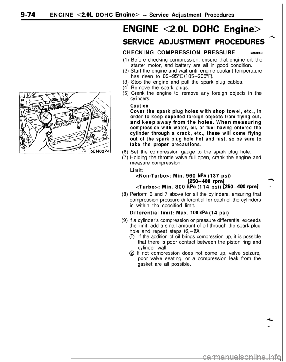
take the proper precautions.(6) Set the compression gauge to the spark plug hole.
(7) Holding the throttle valve full open, crank the engine and
measure compression.
Limit:
[250-400 rpm]6
kPa (114 psi) [250-400 rpml-(8) Perform 6 and 7 above for all the cylinders, ensuring that
compression pressure differential for each of the cylinders
is within the specified limit.
Differential limit: Max. 100 kPa (14 psi)(9) If a cylinder’s compression or pressure differential exceeds
the limit, add a small amount of oil through the spark plug
hole and repeat steps (6)-(8).
@If the addition of oil brings compression up, it is possiblethat there is poor contact between the piston ring and
cylinder wall.
@ If not compression does not come up, valve seizure,
poor valve seating, or a compression leak from the
gasket are all possible.‘I
Page 359 of 1216

_-
a--ENGINE
<2.0L DOHC Engine> -Service Adjustment Procedures9-75
JMANIFOLD VACUUM INSPECTION
NO9FNAO(1) Before inspection and adjustment, put the vehicle into the
following state.
l Engine coolant temperature:
85-g5”C (185-205°F)
l Lights, electric, cooling fan, and accessories: OFF
lTransaxle: Neutral (N or
P for vehicles with an automa-
tic transaxle)
l Steering wheel: Neutral position
(2) Check that the idling revolution speed is normal.
(3) Remove the PCV hose from the PCV valve and attach a
vacuum gauge.
(4) Check that the negative pressure at the intake manifold
during idle revolution is normal.
Standard value:
mmHg (19.3 in.Hg)
mmHg (18.9 in.Hg)(5) If outside the standard value, isolate the cause by referring
to the following table and repair the fault.
ymptomICause1 Remedy
The vacuum gauge reading is less than
standard value, but the pointer is
stable.
The vacuum gauge pointer swingsslowly.
l Ignition timing is retarded.
l Air mixture concentration too
rich.
l Adjust the ignition timing.
l Check ECI-MULTI system.
The vacuum gauge pointer drops
irre-gularly.l Air mixture concentration too
lean.
l Check ECI-MULTI system.
The vacuum gauge pointer drops inter-mittently to 30 to 160
mmHg (1.2 to
6.3 in.Hg).
The vacuum gauge pointer drops sud-
denly from the normal reading to 250
mmHg (9.8 in.Hg), then returns tonormal.
l Incomplete close contact of in-
take and exhaust valve seat.
l Broken cylinder head gasket
l Check and repair the valve.
l Replace cylinder head gasket.
Page 428 of 1216

11-6INTAKE AND EXHAUST - Service Adjustment Procedwes
Wasie gate actuator05AOlSO
TURBOCHARGER SUPERCHARGING PRESSURE
INSPECTIONN1mAAB!PTCautionPerform running inspection with two passengers in the
-’vehicle and where full throttle acceleration can be safely
made.The pressure gauge reading is taken by a front seat
passenger.
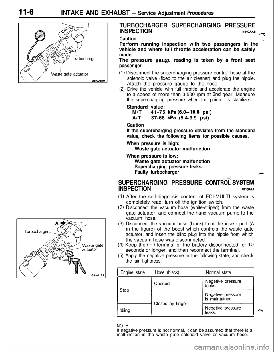
(1) Disconnect the supercharging pressure control hose at the
solenoid valve (fixed to the air cleaner) and plug the nipple.Attach the pressure gauge to the hose.
(2) Drive the vehicle with full throttle and accelerate the engineto a speed of more than 3,500 rpm at
2nd gear. Measure
the supercharging pressure when the pointer is stabilized.Standard value:
M/T41-75
kPa (6.0-10.8 psi)
A/T37-68
kPa (5.4-9.9 psi)
Caution
If the supercharging pressure deviates from the standard
value, check the following items for possible causes.
When pressure is high:Waste gate actuator malfunction
When pressure is low:
Waste gate actuator malfunction
Supercharging pressure leaks
Faulty turbocharger
+-
SUPERCHARGING PRESSURE CONTRtd $YSTEM
INSPECTIONNllGFAA
(1) After the self-diagnosis content of ECI-MULTI system is
completely read, turn off the ignition switch.
(2) Disconnect the vacuum hose (white-striped) from the wastegate actuator, and connect the hand vacuum pump to the
vacuum hose.
(3) Disconnect the vacuum hose (black) from the intake port (Ain the figure) of the boost which controls the waste gate
actuator, and insert the blind plug into the nipple from whichthe vacuum hose was disconnected.
(4) Keep the (- ) terminal of the battery disconnected for 10seconds or longer, and then reconnect the terminal.
(5) Apply the negative pressure in the following state, and check
the air tightness.
IEngine stateHose (black)Normal stateI
stop ;“““*I
NOTEIf negative pressure is not normal, it can be assumed that there is a
malfunction in the waste gate solenoid valve or vacuum hose.