1991 MITSUBISHI ECLIPSE door lock
[x] Cancel search: door lockPage 9 of 1216

INTRODUCTlON AND MASTER TROUBLESHOOTING - Vehicle Identification9
Theft protection label
onginal parts
w ,IeIW
B ,w w
OOA0212For replacement parts
OOA0213
LOCATIONS
THEFT PROTECTIONNowlABIn order to protect against theft, a Vehicle Identification
Number
WIN) is stamped in, or attached as a label to, the
following major parts of the engine and transaxle, as
tiell as
main outer panels:
Engine cylinder block, Transaxle housing, Fender, Door, Quar-
ter panel, Hood, Trunk lid, Bumpers
In addition, a theft-protection label is attached to replacement
parts for the body outer panel main components, and the same
data are stamped into replacement parts for the engine and the
transaxle.Cautions regarding panel repairs
1. When repainting original parts, do so after first mask-
ing the theft-protection label, and, after painting, be
sure to peel off the masking tape.
2. The theft-protection label for replacement parts is
covered by masking tape, so such parts can be paintedas is. The masking tape should be removed after
painting is finished.
3.The theft-protection label should not be removed from
original parts or replacement parts.
OOA0057OOA0055
Page 38 of 1216

0-4 LUBRICATION AND MAINTENANCEScheduled Maintenance Table/Recommended Lubricants- and Lubricant Capacities TableSCHEDULED MAINTENANCE UNDER SEVERE USAGE CONDITIONS
The maintenance items should be performed according to the following table:
F.Mileage Intervals Kilometers in ThousandsSevere Usage
Service to be(Miles in Thousands)ConditionsMaintenance
Item
Performed24 36 48 60 72 80 84 96
(:,:) (15) (22.5) (30) (37.5) (45) (50) (52.5) (60) * B ’ D E F G
Air CleanerReplaceElementMore FrequentlyXX
Spark PlugsReplace
XXXx xx
Engine Oil$$~~~h~vev orEvery 4,800 km (3,000 miles)xxxx x
Engine Oil FilterReplace Every or6 MonthsEvery 9,600 km (6,000 miles)xxxx x
Disc Brake PadsInspect for WearMore FrequentlyXX
Severe usage conditionsA-Driving in dusty conditionsE-Driving in sandy areas
B-Trailer towing or police, taxi, or commercial typeF-Driving in salty areas
operationG-More than 50% operation in heavy city trafic during
C-Extensive idlinghot weather above 32°C (90°F)D-Short trip operation at freezing temperatures
(engine not thoroughly warmed up)
RECOMMENDED LUBRICANTS AND LUBRICANT CAPACITIES TABLENOONA- --z.
RECOMMENDED LUBRICANTS
Items
Engine Oil
Manual Transaxle
TransferRecommended lubricantskF&cesisification
SG or SG/CD (For further details, refer to SAE viscosity
MOPAR Hypoid Gear
Oil/API classification GL4 or higher, SAE 75W-85W
Automatic TransaxleMOPAR ATF PLUS (Automatic Transmission Fluid Type 7176) or Dia
ATF SP or Equivalent
Power SteeringMOPAR ATF PLUS (Automatic Transmission Fluid Type 7176VAutomatictransmission fluid or “DEXRON” or “DEXRON II”
Rear Axle
Brake and Clutch
Rear Wheel BearingsRefer to
P.O-6.
MOPAR Brake Fluid/Conforming to DOT 3
MOPAR Front Wheel Bearing Grease, or MOPAR Multi-MileageLubricant/Multipurpose grease NLGI Grade 2EP
Hood Lock Latch,, Door Lock Strikers,
Seat Adjusters, Lrftgate Lock, Parking
Brake Cable MechanismMOPAR Lubriplate/Multipurpose grease NLGI Grade 2
Engine CoolantMOPAR Antifreeze Permanent-Type Coolant/High quality
ethylene-glycolantifreeze coolant
Door Hinges, Liftgate Hinges
Engine oil
/
N
Page 193 of 1216

BRAKES - Brake Pedal5-53
BRAKE PEDAL
-I REMOVAL AND INSTALLATION
.Pre-removal Operation
aRemoval of Knee Protector
(Refer to GROUP 23%Instrument Panel.)
ORemoval of Lap Cooler Duct and Shower
Duct (L.H.)(Refer to GROUP 23-Instrument Panel.)l Removal of Steering Column Assembly andColumn Support
(Refer to GROUP
19-Steering Wheel andShaft.)*Removal of Relay Box (Indoor)
NO5OA--Post-installation Operation
l installation of Relay Box (Indoor)l Installation of Steering Column Assembly andColumn Support
(Refer to GROUP 19-Steering Wheel and
Shaft.)@Installation of Lap Cooler Duct and Shower
Duct
(L.H.)(Refer to GROUP 23-Instrument Panel.)l Installation of Knee Protector(Refer to GROUP 23-Instrument Panel.)aBrake Pedal Adjustment
(Refer to P.5-41.)20-25 Nm
,‘14-18 ft.lbs.
IO-15 Nm /7-11 ft.lbs.
/
11-17 Nm
8-12 ftlbs.6-9
ftlbs.Removal steps
1. Stop light switch connector
2. Stop light switch
l + 5. Return spring
9.Cotter pin10.Washer11.Clevis pin12.Cotter pin
13. Shift-lock cable connection
20. Lever assembly (A) mounting nut
NOTF(i, Reverse the removal procedures to reinstall.(2) 4I) : Refer to “Service Points of Removal”.(3) l * : Refer to “Service Points of Installation”.
(4) m : Non-reusable parts
(5) *: Vehicles with auto-cruise control system
14A0525
l *
21.Lever
22. Pedal support bracket
24. Lever assembly (A)
25.Bushing
26. Pedal rod
27.Bushing
28.Brake pedal
29. Lever assembly(B) mounting nut
30. Lever assembly
(B)31.Bushing
.20
Page 237 of 1216

CLUTCH - Clutch Pedal6-7
CLUTCH PEDAL
-. REMOVAL AND INSTALLATIONNOSPA-
.“-Pre-removal Operation
*Removal of the Lap Cooler Duct,Shower Duct (L.H.) and Knee Pro-tector (Refer to GROUP 23%lnstru-ment Panel.)*Removal of the Steering ColumnAssembly (Refer to GROUP 19-Steering Wheel and Shaft.)*Removal of the Relay Box (Indoor)
17-26 Nm
12-19 ft.lbs.
11-17 Nm
8-12 ft.lbs.
IO-15 Nm’ tl(i/\:/ Fl/Yv .1-m.---I- I I KIDS.Post-installation Operation
l installation of the Relay Box (Indoor)l installation of the Steering ColumnAssembly (Refer to GROUP 19-Steering Wheel and Shaft.)l installation of the Lap Cooler Duct,Shower Duct (L.H.) and Knee Pro-tector (Refer to GROUP 23 Instru-ment Panel.)l Adjustment of the Brake Pedal (Re-fer to GROUP 5-Service Adjust-ment Procedures.)aAdjustment of the Clutch Pedal (Re-
fer to P.6-5.)
:k -16
20-25 Nm
14-f8 ft.lbs.
Removal steps
I, Clutch pedal return spring
4. Clutch switch
5. Bolt
7. Clip
l + 8. Bushing
9. Turn over spring
e+ IO. Bushing11. Cotter pinl + 12. Washerl + 13. Clevis pin14. Pedal support bracket assembly
15. Clutch pedal mounting nut
16. Clutch pedal bracket17. Lever
l + 18. Clutch pedal bushing~~ 19. Clutch pedal bushing
20. Pedal rod
e+ 21. Brake pedal bushings
22. Clutch pedal
23. Brake pedal
24. Pedal pad
NOTE(1) Reverse the removal procedures to reinstall.(2) l + : Refer to “Service Points of (3) m : Non-reusable parts
Page 1045 of 1216

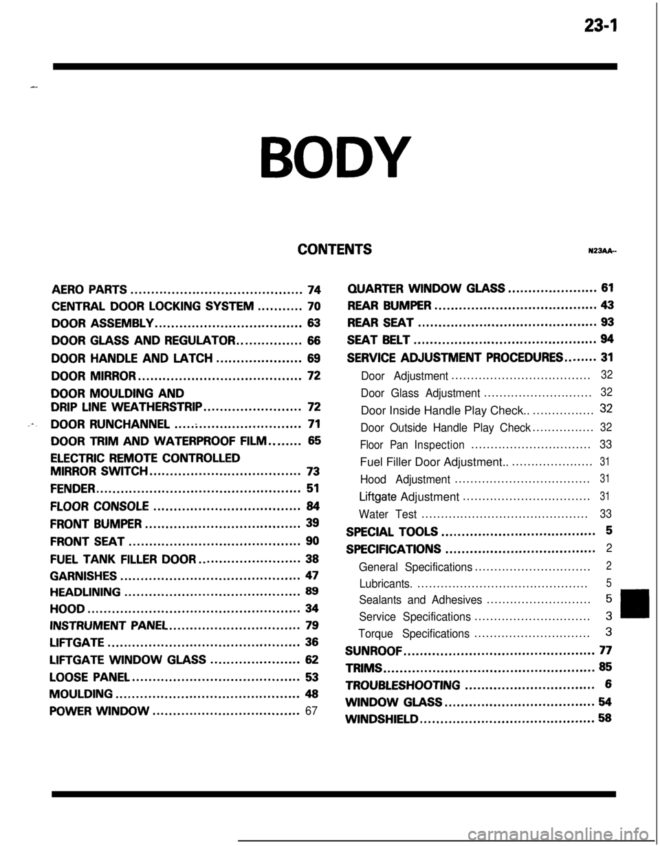
23-lBODY
CONTENTSN23Ak-
AERO PARTS..........................................74
CENTRAL DOOR LOCKING SYSTEM...........70
DOOR ASSEMBLY....................................63
DOOR GLASS AND REGULATOR................66
DOORHANDLEANDLATCH.....................69
DOOR MIRROR........................................72
DOOR MOULDING AND
DRIP LINE WEATHERSTRIP........................72
....DOOR RUNCHANNEL...............................71
DOOR TRIM AND WATERPROOF FILM........65
ELECTRIC REMOTE CONTROLLED
MIRROR SWITCH.....................................73
FENDER..................................................51
FLOOR CONSOLE....................................84
FRONT BUMPER......................................39
FRONT SEAT..........................................90
FUEL TANKFILLERDOOR.........................38
GARNISHES............................................47
HEADLINING...........................................89
HOOD....................................................34
INSTRUMENT PANEL................................79
LIFTGATE...............................................36
LIFTGATE WINDOWGLASS......................62
LOOSE PANEL.........................................53
MOULDING.............................................48
POWER WINDOW....................................67
QUARTERWINDOWGLASS......................61
REAR BUMPER........................................43
REAR SEAT............................................93
SEAT BELT.............................................94
SERVICE ADJUSTMENT PROCEDURES........31
Door Adjustment....................................32
Door Glass Adjustment............................32Door Inside Handle Play Check..................
32
Door Outside Handle Play Check................32
Floor PanInspection...............................
33Fuel Filler Door Adjustment.......................
31
Hood Adjustment...................................31
Liftgate Adjustment.................................31
Water Test...........................................33
SPECIAL TOOLS......................................5
SPECIFICATIONS.....................................2
General Specifications..............................
2
Lubricants.............................................5
Sealants and Adhesives...........................5
Service Specifications..............................3
Torque Specifications..............................3
SUNROOF...............................................77TRIMS
....................................................85
TROUBLESHOOTING................................6WINDOW
GLASS.....................................54
WINDSHIELD...........................................58
Page 1046 of 1216

23-2
SPECIFICATIONS
GENERAL SPECIFICATIONS
BODY - Specifications
N23CA--
Items
Hood
We
Door
Construction
Regulator system
Locking system
Liftgate
We
Slass installation method
Windshield glass
Quarter window glass
Liftgate window glass
Zlass thicknessmm (in.)
Windshield glass
Liftgate window glass
Door glass
Quarter window glass
‘ower window motor
Type
Revolutions under no loadwm
Revolutions under load
wmAt 1
Nm t.72 ft.lbs.1At 2
Nm (1.45 ft.lbs.1Bound current A
Direction of rotation
‘ower window main switch
Type
Rated load currentA
Lock switch
Power window switch
‘ower window sub switch
TvwRated load current A
‘ower window relay
Maximum contact currentA
Rated coil currentA
Voltage drop between terminalsV(At 12 V and the rated load current)
Specifications
Rear hinged, front opening type
Front-hinged, sash construction
Wire type
Pin-fork type
Inner-hinged, with gas damper
Adhesive type
Adhesive type
Adhesive type5.3
i.21)3.5
t.1413.5
t.1413.5
t.141
Permanent magnet type (Built-in circuit breaker)
75 or more65-95
50-80
34 or less
Clockwise and counter-clockwise
Automatic reset type
10
10
Automatic reset type
10
20
Max. 0.2
0.2 or less
Page 1047 of 1216

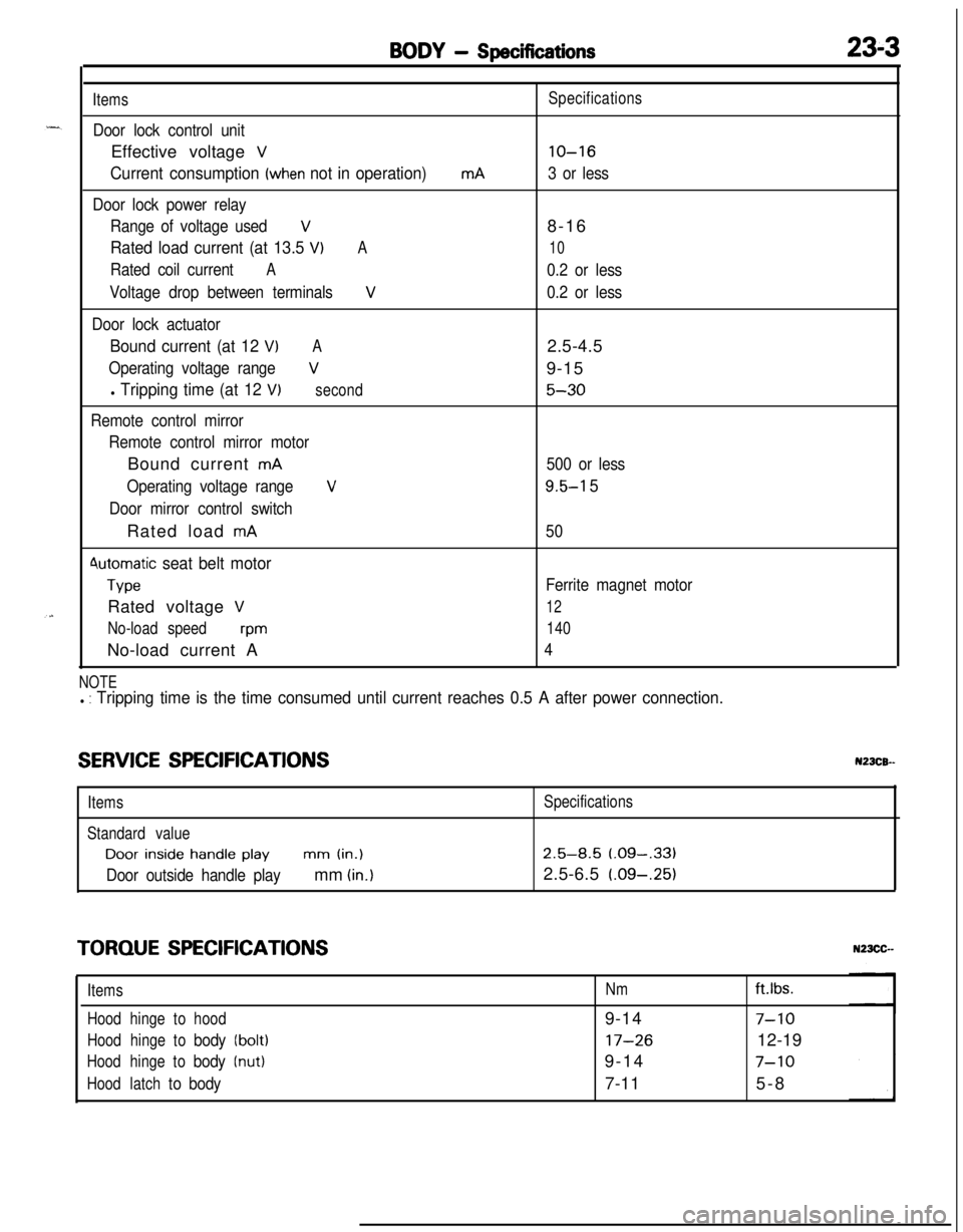
BODY - Specifications23-3
Items
Door lock control unitEffective voltage
V
Current consumption (when not in operation)
Door lock power relay
Range of voltage used
V
Rated load current (at 13.5 VIA
Rated coil currentA
Voltage drop between terminalsV
Door lock actuator
Bound current (at 12 VIA
Operating voltage rangeV
l Tripping time (at 12 V)second
Remote control mirror
Remote control mirror motorBound current
mA
Operating voltage range
V
Door mirror control switchRated load
mA
4utomatic seat belt motor
TypeRated voltage
V
No-load speedwmNo-load current A
mASpecifications
lo-16
3 or less8-16
10
0.2 or less
0.2 or less2.5-4.5
9-15
5-30
500 or less
9.5-l 5
50
Ferrite magnet motor
12
140
4
NOTEl : Tripping time is the time consumed until current reaches 0.5 A after power connection.
SERVICE SPECIFICATIONSN23CB--
ItemsSpecifications
Standard valueDoor
inside handle playmm (in.)2.5-8.5 (.09-,331
Door outside handle playmm (in.)2.5-6.5 (.09-.25)
TORQUE SPECIFICATIONS
ItemsNmft.lbs.
Hoodhingetohood9-14
7-10
Hoodhingetobody(bolt)17-2612-19
Hoodhingetobody(nut)9-147-10
Hoodlatchtobody7-115-8
Page 1048 of 1216

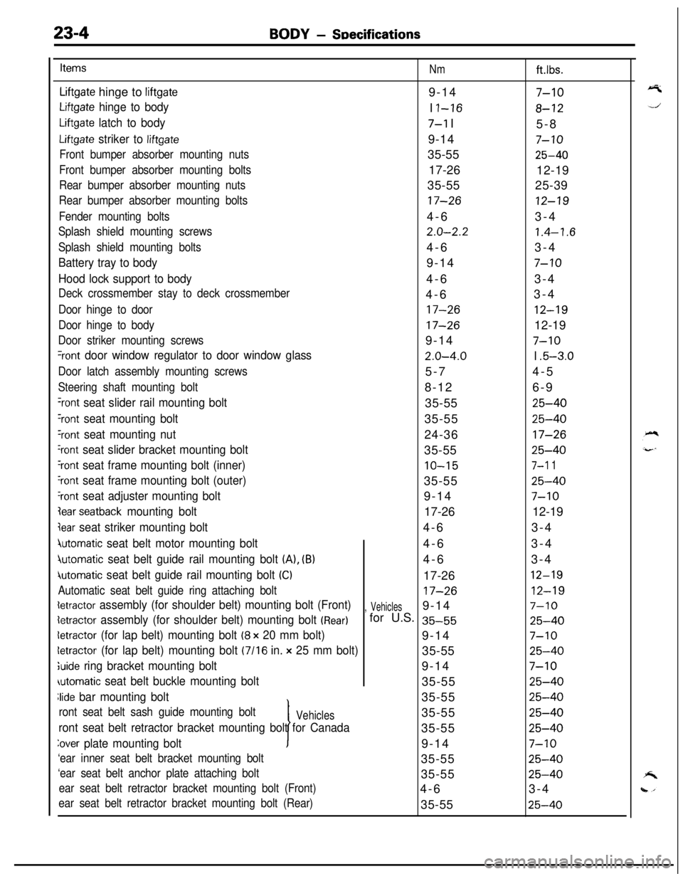
23-4BODY - SDecifications
Items
Nmft.lbs.
Liftgate hinge to liftgate9-147-10
Liftgate hinge to bodyI I-168-12
Liftgate latch to body7-l I
5-8
Liftgate striker to liftgate9-147-10
Front bumper absorber mounting nuts35-5525-40
Front bumper absorber mounting bolts17-26
12-19
Rear bumper absorber mounting nuts35-5525-39
Rear bumper absorber mounting bolts17-2612-19
Fender mounting bolts4-63-4
Splash shield mounting screws2.0-2.21.4-1.6
Splash shield mounting bolts4-63-4
Battery tray to body9-147-10
Hood lock support to body4-63-4
Deck crossmember stay to deck crossmember4-63-4
Door hinge to door17-2612-19
Door hinge to body17-2612-19
Door striker mounting screws9-147-10
%ont door window regulator to door window glass2.0-4.0I .5-3.0
Door latch assembly mounting screws5-74-5
Steering shaft mounting bolt8-126-9
‘rant seat slider rail mounting bolt35-5525-40
Yont seat mounting bolt35-5525-40
‘rant seat mounting nut24-3617-26
‘rant seat slider bracket mounting bolt35-5525-40
‘rant seat frame mounting bolt (inner)10-157-l 1
‘rant seat frame mounting bolt (outer)35-5525-40
‘rant seat adjuster mounting bolt9-147-10
lear seatback mounting bolt17-2612-19
jear seat striker mounting bolt4-63-4
4utomatic seat belt motor mounting bolt4-63-4
jutomatic seat belt guide rail mounting bolt (A), (B)4-63-4
iutomatic seat belt guide rail mounting bolt (Cl17-2612-19
Automatic seat belt guide ring attaching bolt17-2612-19
detractor assembly (for shoulder belt) mounting bolt (Front), Vehicles9-147-10
detractor assembly (for shoulder belt) mounting bolt (Rear)for U.S. 35-5525-40
detractor (for lap belt) mounting bolt (8 x 20 mm bolt)9-147-10
letractor (for lap belt) mounting bolt (7116 in. x 25 mm bolt)35-5525-40
;uide ring bracket mounting bolt9-147-10
automatic seat belt buckle mounting bolt35-5525-40
Jide bar mounting bolt
I35-55
25-40
ront seat belt sash guide mounting boltVehicles35-5525-40
ront seat belt retractor bracket mounting bolt for Canada35-5525-40
Zover plate mounting bolt9-147-10
‘ear inner seat belt bracket mounting bolt35-5525-40
‘ear seat belt anchor plate attaching bolt35-5525-40
ear seat belt retractor bracket mounting bolt (Front)4-63-4
ear seat belt retractor bracket mounting bolt (Rear)35-5525-40