Page 4 of 1216

4INTRODUCTION AND MASTER TROUBLESHOOTING - How to use This ManualEXPLANATION OF THE TROUBLESHOOTING GUIDE
3. Checking the passenger compartment-temperature sensor, outside-air sensor, air-thermostat sensor and refrigerant-temperature sensor circuitsrIndicatesthe
circuit diagram
for
checking(including the
interface of the
air conditioner
control unit).
II*
in the opera-
tion
descrip-tions only as
necessary, and
these numbers
correspond to
the
numbers
usedin har-
ness and com-
ponent layout
l 1
I--
Operation descriptionA negative-characterlstlc thermstor 1s employed for each sensor in order 10 convey the amblenttemperature of the sensor pan ,o resistanceThe sensor power-supply I2 5V) of the awcondltww““I,ISappliedtothelermlnals116).(15).(17)(5)dlvldedres~~,ancereSlSta”ceR
Providesthe
scription of cir-
cuit operation
for basic under-
standing.
I
diaarams.Tmublrhooting 4DlagnoslsNo 12 The
ou,s,de-a,, sensor ,nput slgnal IS held to 15°C 159°F)No 13 The air-thermostat tensor ~np”t slgnal IS held 10 4°C 139°F)Provides hints
(including
judgement)when trouble-
cedures are fol-
lowed.
ITerminalI S’g”a’CO”dl,,O”*Terminal voltageNO
I
1
Indicatesthe
diagnosis out-
put code No.
and the system
conditions
dur-
kng output.
theconditions un-
der which the
be made.Indicates the specification to
be used for judgement of
the check results.
If there is no particular men-
tion of conditions in the
“Conditions” column, the
column shows the specifica-
tion under normal condi-
tions.
Page 5 of 1216
INTRODUCTION AND MASTER TROUBLESHOOTING - ‘How to use miS .Manual5EXPLANATION OF CIRCUIT
DIAGRAMS
-IThe symbols used in circuit diagrams are used as
described below.NOTEFor detailed information
cqncqning the reading of
circuit diagrams, refer to GROUP
8-Wi@ng Har-
ness.
The input/output (dire%%of current flow) relative to
the electronic control unit
isindicated by symbols
(A.m.The (A) symbol indicates
that current flows in the
upward direction.
OutputIndicates a
connector.
IGNITIONSWITCH(IG1)Input
.A Input/output
reht flow is indicat-:ed by the arrow.
In this instance, the
current flow is in
both directions, up
Theconnector
symbol indicates
the device side
connector (for an
intermediate con-
nector, the male
sideconnector)as seen from the
terminalfront
(the connector’s
connection face).cdevice side con- device side con-
L
I
\
Indicatesthe
branch point of a
harness of a differ-ent line diameter
nr line colour.I Indicates
that the con-
nector is the
direct-inser-tion type.
Page 254 of 1216
7-6COOLING - Troubleshooting
CIRCUIT DIAGRAM
ON(IG2)SUB FUSIBLE LINK @IGNI:SWIT(: LINK@MAIN FUSIB:
0
.-----
IN
1
A-18X
1CONDENSER
A-20X ,
I!31P2
RESISTOR
(CONDENSER'
FAN MOTOR,
A-32
m
A-21
IQ
Ed3B4SB
CONDENSER$l
FAN MOTOR2
12
lal34I
A-32
0
I
I
CONDENSER FAN
MOTOR RELAYA-03X
I 2lm34
A-22
CONDENSER
t----lTH RMOBE 80R
;;aIATOR ci
ASSEMBLY'
C-72
RADIATORFANMOTOR (
A-40
II
i0
A
6
KX35-AC-U0802-NC
Page 377 of 1216

ENGINE <2.0L DOHC Engine> - Cylinder Head Gasket9-93
DlADD3fFront of
engine+Exhaust side
OlR0391Cylinder
he/d-Ani-circularpackingSERVICE POINTS OF INSTALLATIONNOSJDDls
48. INSTALLATION OF CYLINDER HEAD GASKET
(1)Use a scraper to clean the gasket surface of the cylinder
block.
Caution
Take care that no foreign material gets into the
cylinder, or into coolant passages or oil passages.(2) Make sure that the gasket has the proper identification
mark for the engine.
(3) Lay the cylinder head gasket on the cylinder block with
the identification mark at the front top.
47. INSTALLATION OF CYLINDER HEAD ASSEMBLY
(1)Use a scraper to clean the gasket surface of the cylinderhead assembly.
Caution
Take care that no foreign material gets into the
coolant passages or oil passages.(2) Using the special tool and a torque wrench, tighten the
bolts to the specified torque in the order shown in the
figure. (in two or three cycles)
Caution
Install the head bolt washers as shown in the
diagram.
41. APPLICATION OF SEALANT TO SEMI-CIRCULAR PACK-
ING
Apply a coating of the specified sealant to the semi-circularpacking and the cylinder head to top surfaces.
Specified sealant: MOPAR Part No.4318034 or equiva-
lent
Page 882 of 1216

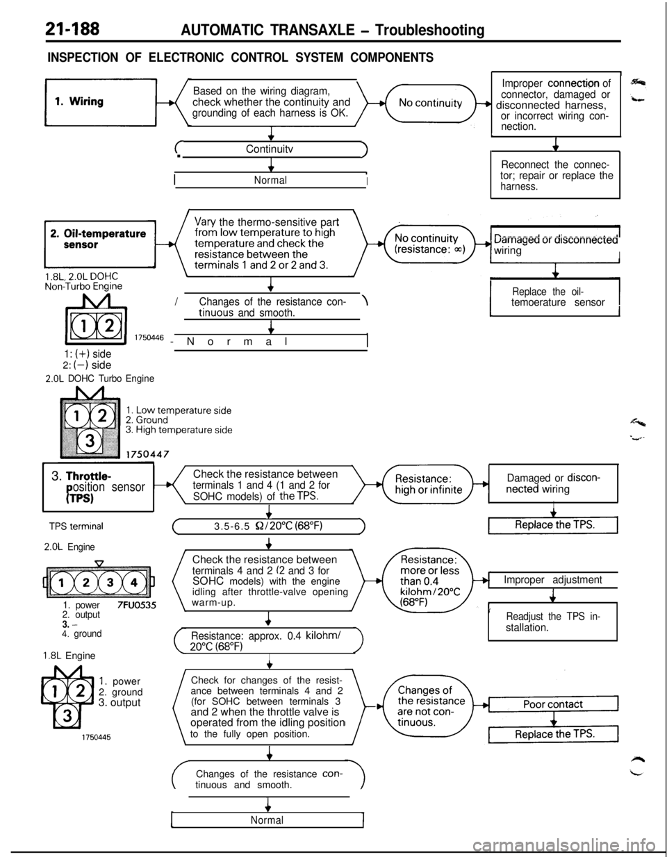
21-188AUTOMATIC TRANSAXLE - Troubleshooting
INSPECTION OF ELECTRONIC CONTROL SYSTEM COMPONENTS
Based on the wiring diagram,check whether the continuity and
grounding of each harness is OK.
+
cContinuitvJ.
4
/
.NormalI
1
Improper connection of
connector, damaged or
+ disconnected harness,or incorrect wiring con-
nection.
L
J1
Reconnect the connec-
tor; repair or replace the
harness.
I\
Vary the thermo-sensitive part
uarriageu ur ursconnecreawiring
I/
IReplace the oil-Chanaes of the resistance con-\temoerature sensortinuo& and smooth.4
I 1750446 -Normal,
1: (+) side2:
(-) side
2.0L DOHC TurboEngine
1I
Y3.
Throttle-Check the resistance betweenosition sensorterminals 1 and 4 (1 and 2 forDamaged or discon-
PTPS)SOHC models) of theTPS.netted wiringI
I
TPS termrnal
2.0L Engine
1. power
7FUO5352. output3. -4. ground
1.8L Engine
1. power
2. ground
3. output
+
(3.5-6.5 S2/2O”C (68°F)1Check the resistance between
terminals 4 and 2 (2 and 3 forSOHC models) with the engine
idling after throttle-valve opening
warm-up.
4
Resistance: approx. 0.4 kilohml
20°C (68°F)I
Improper adjustment
J
’Readjust the TPS in-
stallation.Check for changes of the resist-
ance between terminals 4 and 2
(for SOHC between terminals 3
and 2 when the throttle valve is
operated from the idling position
to the fully open position.
4Changes of the resistance con-
tinuous and smooth.
4
Normal
Page 897 of 1216
AUTOMATIC TRANSAXLE - Troubleshooting21-203
CIRCUIT DIAGRAM
J/B
63IOA
0
'13l-----AWD1
cL
13 C-67
1
'OU'EiRaPPLl
--b
7
1'
I
I
3
xl:- 71
03
4
I
L--
-----------------16 C-502zs
4
C-58
El
THEFT-ALARM
CONTROL UNIT
INHIBITORSWITCH
B-25
r
STARTER MOTOR
X35-AC-U0705-NC
Page 1053 of 1216
BODY - Troubleshooting23-9
POWER WINDOW
CIRCUIT DIAGRAM
N23EBEE
MAIN SWITCHE-53JIGl=MJ
ONE-TOUCH WWN CIFXXJITJ/B
I
8
c
\,:
-0
t
!Ti
i
15(A/T) C-67
'1OWT) C-67
5
e,,*
'\ A-05X
-------___-_
1
\I2
OWER WINDOWELAY
128 C-7
El468
-
&
POWER WINDOW
MOTOR
E-54
:3S-AC-UllO?-NC
Page 1055 of 1216
BODY - Troubleshooting234'1
CENTRAL DOOR LOCKING SYSTEM N23EBFF
CIRCUIT DIAGRAM..-
,-.
SUB FU0IBLELINK 8
g
J/Bk 1 c-47 'B
@
L
10A
L
is411
J/B
L
4c
c-51
c-49
12
al34
3 E-64
DOOR LOCKE-49DOOR LOCKE-09
KX3b-AC-WIOB-Xi: