1991 MITSUBISHI ECLIPSE charging
[x] Cancel search: chargingPage 423 of 1216
11-l
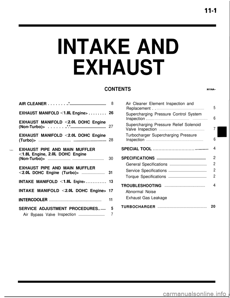
INTAKE AND
EXHAUSTAIR CLEANER
. . . . . . . ..*........................................8
EXHAUST MANIFOLD <1.8L Engine> . . . . . . . .26
EXHAUST MANIFOLD
<2.0L DOHC Engine
(Non-Turbo)>
. . . . . . ..*.*.......................................27EXHAUST MANIFOLD
<2.0L DOHC Engine
(Turbo)>
. . . . . . . . . . . . . . . . . . . . . . . . . . . . . .*...........................28
CONTENTSNllAA--
-EXHAUST PIPE AND MAIN MUFFLER<1.8L Engine,
2.0L DOHC Engine
(Non-Turbo)>
. . . . . . . . . . . . . . . . . . . . .. . . . . . . . . . . . . . . . . . . . . . . . . . . . .30EXHAUST PIPE AND MAIN MUFFLER<2.0L
DOHCEngine(Turbo)>. . . . . . . . . . . . . . . . . . . . .31INTAKE MANIFOLD
<1.8LEngine> . . . . . . . . . . . .13INTAKE MANIFOLD
<2.0L DOHC Engine> 17
INTERCOOLER. . . . . . . . . . . . . . . . . . . . . . . . . . . . . . . . . . . . . . . . . . . . . . . . .11SERVICE ADJUSTMENT PROCEDURES..
.....5Air
Bypass ValveInspection........................7Air Cleaner Element Inspection and
Replacement . .
. . . . . . . . . . . . . . . . . . . . . . . . . . . . . . . . . . . . . . . . . . . . .5Supercharging Pressure Control System
Inspection
.,...... . . . . . . . . . . . . . . . . . . . . . . . . . . . . . . . .. . . . . . . . . . . . . .6Supercharging Pressure Relief Solenoid
Valve Inspection
. . . . . . . . . . . . . . . . . . . . . . . . . . . . . . . . . . . . . . . . . . .7Turbocharger Supercharging Pressure
Inspection. . . . . . . . . . . . . . . . . . . . . . . . . . . . . . . . . . . . . . . . . . . . . . . . . . . . . .6SPECIAL TOOL
. . . . . . . . . . . . . . . . . . . . . . . . . . . . . ..#................4
SPECIFICATIONS.............................................2General Specifications
..................................2Service Specifications
...................................2Torque Specifications
...................................2
TROUBLESHOOTING. . . . . . . . . . . . . . . . . . . . . . . . . . . . . . . . . . . . . .4
Abnormal Noise
Exhaust Gas Leakage
TURBOCHARGER
. . . . . . . . . . . . . . . . . . . . . . . . . . . . . . . . . . . . . . . . . . . .20
Page 424 of 1216
11-2INTAKE AND EXHAUST - Specifications
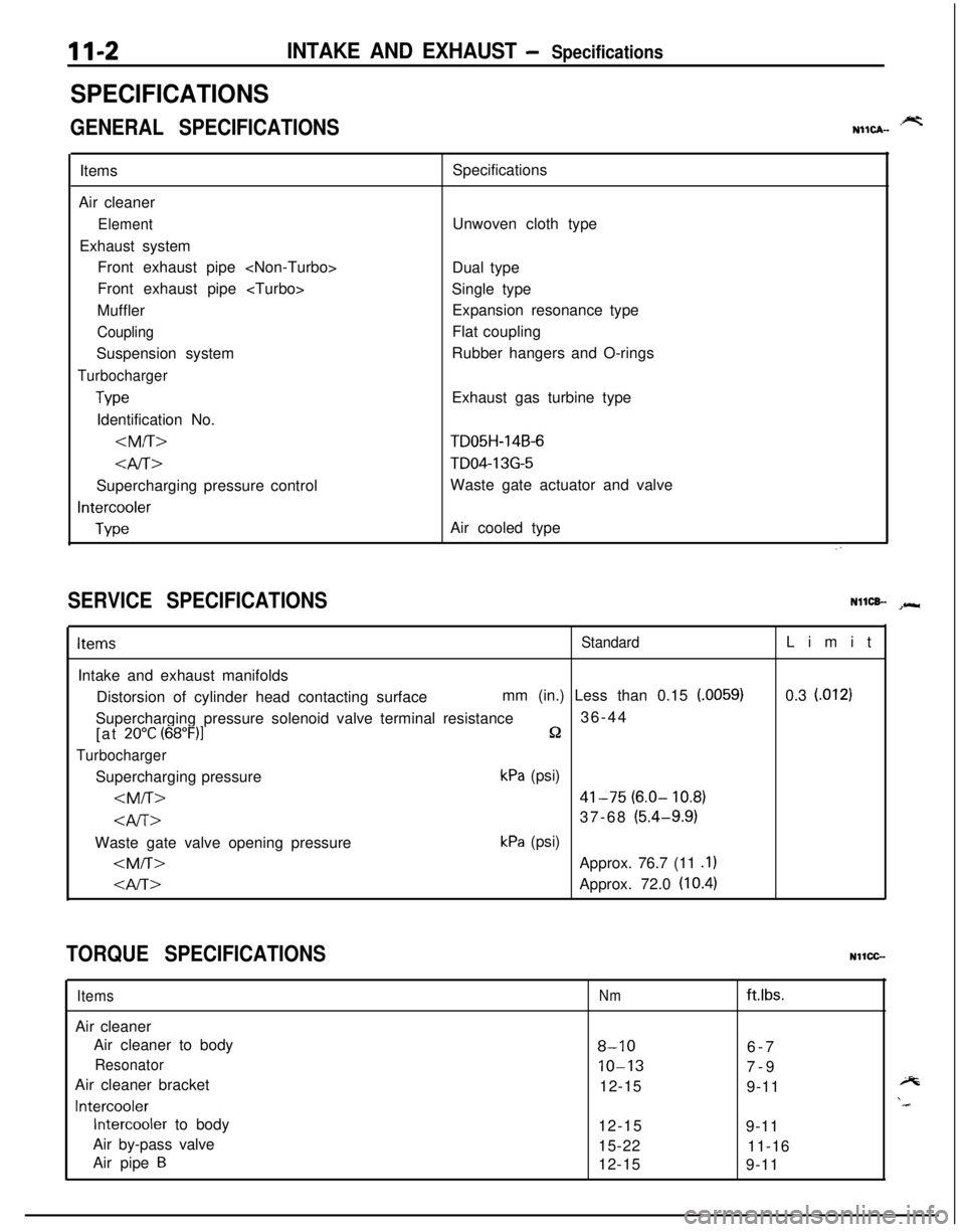
SPECIFICATIONS
GENERAL SPECIFICATIONS.prtNIICA-Items
Air cleaner
ElementExhaust system
Front exhaust pipe
Front exhaust pipe
Muffler
CouplingSuspension system
Turbocharger
TypeIdentification No.
4iT>Supercharging pressure control
Intercooler
TypeSpecifications
Unwoven cloth type
Dual type
Single type
Expansion resonance type
Flat coupling
Rubber hangers and O-rings
Exhaust gas turbine type
TD05H-14B-6
TD04-13G-5Waste gate actuator and valve
Air cooled type
SERVICE SPECIFICATIONSNllCB- spr*
ItemsStandardIntake and exhaust manifolds
Distorsion of cylinder head contacting surfacemm (in.) Less than 0.15
(.0059)Supercharging pressure solenoid valve terminal resistance36-44
[at
20°C (68”F)lQ
TurbochargerSupercharging pressure
kPa (psi)
kPa (psi)
0.3
l.0121
TORQUE SPECIFICATIONSNllCC-
ItemsAir cleaner
Air cleaner to body
ResonatorAir cleaner bracket
Intercooler
Intercooler to body
Air by-pass valve
Air pipe
B
Nmftlbs.
8-106-7
10-137-9
12-15
9-11
12-15
9-11
15-22
11-16
12-15
9-11
Page 428 of 1216
11-6INTAKE AND EXHAUST - Service Adjustment Procedwes
Wasie gate actuator05AOlSO
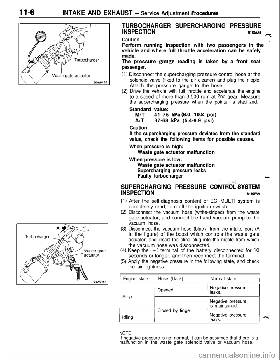
TURBOCHARGER SUPERCHARGING PRESSURE
INSPECTIONN1mAAB!PTCautionPerform running inspection with two passengers in the
-’vehicle and where full throttle acceleration can be safely
made.The pressure gauge reading is taken by a front seat
passenger.
(1) Disconnect the supercharging pressure control hose at the
solenoid valve (fixed to the air cleaner) and plug the nipple.Attach the pressure gauge to the hose.
(2) Drive the vehicle with full throttle and accelerate the engineto a speed of more than 3,500 rpm at
2nd gear. Measure
the supercharging pressure when the pointer is stabilized.Standard value:
M/T41-75
kPa (6.0-10.8 psi)
A/T37-68
kPa (5.4-9.9 psi)
Caution
If the supercharging pressure deviates from the standard
value, check the following items for possible causes.
When pressure is high:Waste gate actuator malfunction
When pressure is low:
Waste gate actuator malfunction
Supercharging pressure leaks
Faulty turbocharger
+-
SUPERCHARGING PRESSURE CONTRtd $YSTEM
INSPECTIONNllGFAA
(1) After the self-diagnosis content of ECI-MULTI system is
completely read, turn off the ignition switch.
(2) Disconnect the vacuum hose (white-striped) from the wastegate actuator, and connect the hand vacuum pump to the
vacuum hose.
(3) Disconnect the vacuum hose (black) from the intake port (Ain the figure) of the boost which controls the waste gate
actuator, and insert the blind plug into the nipple from whichthe vacuum hose was disconnected.
(4) Keep the (- ) terminal of the battery disconnected for 10seconds or longer, and then reconnect the terminal.
(5) Apply the negative pressure in the following state, and check
the air tightness.
IEngine stateHose (black)Normal stateI
stop ;“““*I
NOTEIf negative pressure is not normal, it can be assumed that there is a
malfunction in the waste gate solenoid valve or vacuum hose.
Page 429 of 1216
INTAKE AND EXHAUST - Service Adjustment ProceduresII-7
w05A0155
h61
NO06061
NO0616 I
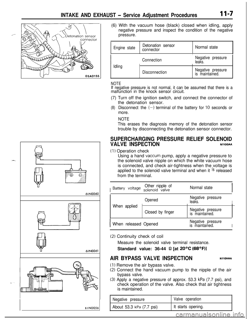
NO056(6) With the vacuum hose (black) closed when idling, apply
negative pressure and inspect the condition of the negative
pressure.
Engine stateDetonation sensor
connectorNormal state
,
ConnectionNegative pressureleaks.
Idling
DisconnectionNegative pressure
is maintained.
NOTEIf negative pressure is not normal, it can be assumed that there is amalfunction in the knock sensor circuit.(7) Turn off the ignition switch, and connect the connector of
the detonation sensor.
(8)Disconnect the (-) terminal of the battery for 10 seconds or
more.
NOTE
This erases the diagnosis memory of the detonation sensortrouble by disconnecting the detonation sensor connector.
SUPERCHARGING PRESSURE RELIEF SOLENOID
VALVE INSPECTIONNllGGAA
(1) Operation check
Using a hand
vaccum pump, apply a negative pressure to
the solenoid valve nipple on which the white vacuum hose
is connected, and check air-tightness when the voltage is
applied to the solenoid valve terminal and when it i‘s releasedfrom the terminal.
I
Other nipple ofBattery voile solenoid valveNormal state
OpenedNegative pressureleaks.IWhen applied
Closed by fingerNegative pressure
is maintained.
IWhen released OpenedNegative pressure
is maintained.
I
(2) Continuity check of coil
Measure the solenoid valve terminal resistance.Standard value: 36-44
fl [at 20°C (68OF)l
AIR BYPASS VALVE INSPECTIONNllGHAA
(1) Remove the air bypass valve.
(2) Connect the hand vacuum pump to the nipple of the air
bypass valve.
(3) Apply a negative pressure of approx. 53.3 kPa (7.7 psi), andcheck operation of the valve. Also check that air tightness
is maintained.
Negative pressure
About 53.3 kPa (7.7 psi)
Valve operation
It starts opening.
Page 1154 of 1216
24-10HEATERS AND AIR CONDITIONING - Safety Precautions
SAFETY PRECAUTIONSN24PAAD
The refrigerant used in all air conditioner is R-l 2. It istransparent and colorless in both the liquid and
vapor state. Since it has a boiling point of
-29.8”C(-85.6”F).
at atmospheric pressure, it will be a vapor
at all normal temperatures and pressures. The vaporis heavier than air, non-flammable, and nonexplo-
sive. It is nonpoisonous except when it is in direct
contact with open flame. It
ia noncorrosive except
when combined with water. The following precau-
tions must be observed when handling
R-12.Caution
Wear safety goggles when servicing the refriger-ation system.
R-12 evaporates so rapidly at normal atmospheric
pressures and temperatures that it tends to freeze
anything it contacts. For this reason, extreme care
must be taken to prevent any liquid refrigerant from
contacting the skin and especially the eyes. Always
wear safety goggles when servicing the refrigera-
tion part of the air conditioning system. Keep a
bottle of sterile mineral oil handy when working on
the refrigeration system. Should any liquid re-
frigerant get into the eyes, use a few drops of
mineral oil to wash them out.
R-12 is rapidly
absorbed by the oil. Next splash the eyes with
plenty of cold water. Call your doctor immediately
even though irritation has ceased after treatment.
Caution
Do not heat
R-12 above 40°C (104°F).In most instances, moderate heat is required to
bring the pressure of the refrigerant in its container
above the pressure of the system when charging or
adding refrigerant. A bucket or large pan of hot
water not over
40°C (104°F) is all the heat required
for this purpose. Do not heat the refrigerant contain-
er with a blow torch or any other means that would
raise temperature and pressure above this tempera-ture. Do not weld or steam clean on or near the
system components or refrigerant lines.
Caution
Keep
R-12 containers upright when charging the
system.When metering
R-12 into the refrigeration system,
keep the supply tank or cans in an upright position. Ifthe refrigerant container is on its side or upside
down, liquid refrigerant will enter the system and
damage the compressor.Caution
Always work in a well-ventilated room.
‘irrGood ventilation is vital in the working area. Always
discharge the refrigerant into the service bay ex-
haust system or outside the building. Large quanti-
ties of refrigerant vapor in a small, poorly ventilated
room can displace the air and cause suffocation.
Although
R-12 vapor is normally nonpoisonous,
contact with an open flame can cause the vapor to
become very poisonous. Do not discharge large
quantities of refrigerant in an area having an open
flame. A poisonous gas is produced when using theflame-type leak detector. Avoid inhaling the fumes
from the leak detector.
Caution
Do not allow liquid refrigerant to touch bright
metal.
Refrigerant will tarnish bright metal and chrome
surfaces, and in combination with moisture can
severely corrode all metal surfaces.
R-12 Refrigerant Bundling
Refrigerant Recycling
R-12 refrigerant is a chloro-floro-carbon (CFC) that
can contribute to the depletion of the ozone layer in
the upper atmosphere.A
Ozone filters out harmful radiation from the sun.
- -/.To assist in protecting the ozone layer, Mitsubishi
Motors Corporation
recomends that a R-12 re-
frigerant recycling device that meets SAE standard
J1991 be used.
Contact an automotive service equipment supplier
for refrigerant recycling equipment that is available
in your area.
Refer to the operating instructions provided with therecycling equipment for proper operation.
Page 1155 of 1216
HEATERS AND AIR CONDITIONING - Service Adjustment Procedures 24-I 1
SERVICE ADJUSTMENT PROCEDURES
MANIFOLD GAUGE SET INSTALLATION
Suction
gauge
N24FDAF
Discharge
hose
7 Discharge
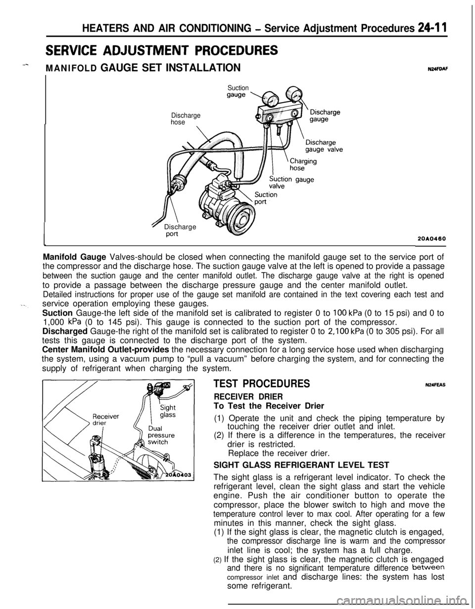
Port20A0460Manifold Gauge Valves-should be closed when connecting the manifold gauge set to the service port of
the compressor and the discharge hose. The suction gauge valve at the left is opened to provide a passage
between the suction gauge and the center manifold outlet. The discharge gauge valve at the right is openedto provide a passage between the discharge pressure gauge and the center manifold outlet.
Detailed instructions for proper use of the gauge set manifold are contained in the text covering each test andservice operation employing these gauges.
Suction Gauge-the left side of the manifold set is calibrated to register 0 to
100 kPa (0 to 15 psi) and 0 to
1,000
kPa (0 to 145 psi). This gauge is connected to the suction port of the compressor.
Discharged Gauge-the right of the manifold set is calibrated to register 0 to
2,100 kPa (0 to 305 psi). For all
tests this gauge is connected to the discharge port of the system.
Center Manifold Outlet-provides the necessary connection for a long service hose used when discharging
the system, using a vacuum pump to “pull a vacuum”before charging the system, and for connecting the
supply of refrigerant when charging the system.
TEST PROCEDURESN24FEAS
RECEIVER DRIERTo Test the Receiver Drier
(1) Operate the unit and check the piping temperature by
touching the receiver drier outlet and inlet.
(2) If there is a difference in the temperatures, the receiver
drier is restricted.
Replace the receiver drier.
SIGHT GLASS REFRIGERANT LEVEL TEST
The sight glass is a refrigerant level indicator. To check the
refrigerant level, clean the sight glass and start the vehicle
engine. Push the air conditioner button to operate the
compressor, place the blower switch to high and move the
temperature control lever to max cool. After operating for a fewminutes in this manner, check the sight glass.
(1) If the sight glass is clear, the magnetic clutch is engaged,
the compressor discharge line is warm and the compressorinlet line is cool; the system has a full charge.
(2) If the sight glass is clear, the magnetic clutch is engaged
and there is no significant temperature difference between
compressor inlet and discharge lines: the system has lost
some refrigerant.
Page 1156 of 1216

24-12 HEATERS AND AIR CONDITIONING - Service Adjustment Procedures
------__--210 2352,100 Pressure
(30) (33)(299) 2&
kPa(psi)2OPOO14(3) If the sight glass is clear and the magnetic clutch is
disengaged; the clutch is faulty or, the system is out of
refrigerant. Perform low pressure switch test to determine
condition. Check low pressure switch, and clutch coil for
electrical continuity.
(4) If the sight glass shows foam or bubbles, the system could
be low on charge. Occasional foam or bubbles are normal
when the ambient temperature is above
43°C (110°F) or
below
21°C (70°F).Adjust the engine speed to 1,500 rpm. Block the air-flow
thru the condenser to increase the compressor discharge
pressure to 1,422 to 1,520
kPa (206 to 220 psi). If sight
glass still shows bubbles or foam, system charge level is
low.The refrigerant system will not be low on charge unless
there is a leak. Find and repair the leak. If the leak can be
repaired without discharging the system an oil level check
is not necessary. Use the procedure for correcting low
refrigerant level found in the Refrigerant System Service
Procedure Section.DUAL PRESSURE SWITCH
The dual-pressure switch is a combination of the low-pressureswitch (for checking the quantity of refrigerant) and the,
high-pressure switch (for prevention of overheating); it is
installed on the tube, and, when the pressure becomes
approximately 210 kPa (30 psi) or lower, the compressor stops,thus preventing the compressor from being damaged by heat.
When the pressure reaches 2,700
kPa (384 psi) or higher, the
compressor stops, thus preventing overheating. There is
generally no necessity for inspection; if, however, an unusual
condition, such as non-operation of the compressor is encoun-tered, check by following the procedures below.
(1) Check for continuity of the dual-pressure switch.
NOTEIf the air temperature drops to
0°C (32°F) or lower during
cold weather, the air conditioner will not operate (no
continuity).(2) If there is an insufficient amount of refrigerant, check the
refrigerant amount by looking through the sight glass of thereceiver; supply refrigerant if necessary.
(Refer to P.24-21.)
Page 1161 of 1216
HEATERS AND AIR CONDITIONING - Service Adjustment Procedures 24-Q
ilectric leakletector tester
2OUO333
40°C(I 04°F)20A0463
REFRIGERANT LEAK REPAIR PROCEDURE N24FtiAOLost Charge
If the system has lost all charge due to a leak:
(1) Evacuate the system. (See procedure.)
(2) Charge the system with approximately one pound of
refrigerant.(3) Check for leaks.
(4) Discharge the system.
(5) Repair leaks.
(6) Replace receiver drier.
Caution
Replacement filter-drier units must be sealed while in
storage. The drier used in these units will saturate
water quickly upon exposure to the atmosphere. When
installing a drier, have all tools and supplies ready for
quick reassembly to avoid keeping the system open
any longer than necessary.
(7) Evacuate and charge the system.
Low Charge
If the system has not lost all of its refrigerant charge; locate
and repair all leaks. If it is necessary to increase the system
pressure to find the leak (because of an especially low charge)add of refrigerant. If it is possible to repair the leak without
discharging the refrigerant system, use the procedure for
correcting low refrigerant level.
CORRECTING LOW REFRIGERANT LEVEL
Since the refrigeration system is completely sealed, refrigerant
level will not be low unless there is a leak in the system. Beforeadding refrigerant when the cause of low level is not known,
the system should be tested for leaks. Assuming that leaks
have been corrected without discharging the system, proceed
with partial charge.
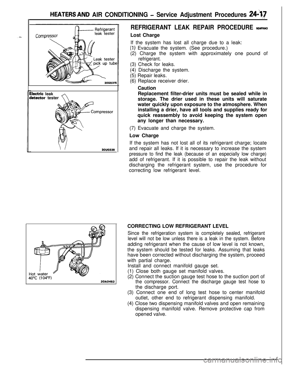
Install and connect manifold gauge set.
(1) Close both gauge set manifold valves.
(2) Connect the suction gauge test hose to the suction port of
the compressor. Connect the discharge gauge test hose tothe discharge port.
(3) Connect one end of long test hose to center manifold
outlet, other end to refrigerant dispensing manifold.
(4) Close two dispensing manifold valves and open remaining
dispensing manifold valve. Remove protective cap from
opened valve.