Page 547 of 1216
FUEL SYSTEM - Fuel Tank
FUEL TANK cFWD>
,*. REMOVAL AND INSTALLATION
q?&g
NlMA-30-40 Nm
2-3 Nm22-29 ft.lbs.
---15-20 Nm
11-14 ft.lbs.
15-22 ft.lbs.Removal steps
l + 1. Return hosel +2. Vapor hose
3. Clamp
4. Fuel gauge unit connector
5. Electrical fuel pump connector
l + l q6. High pressure fuel hose
l + 7. Filler hose
l + 8. Vapor hose
~~ 9. Self-locking nut10. Tank band11. Fuel tank
l + 12. Vapor hosel + 13. Overfill limiter (Two-way valve)I)+ 14. Fuel gauge unitl + 15. Electrical fuel pump16. Drain plug
17. Fuel tank cap
18. Packing
19. Fuel filler neck$TEeverse the removal procedures to reinstall,(2) +e : Refer to “Service Points of Removal”:,,
(3) *+ : Refer to “Service Points of lnstallatlon .(4) m : Non-reusable parts
Page 548 of 1216

14-94FUEL SYSTEM - Fuel Tank
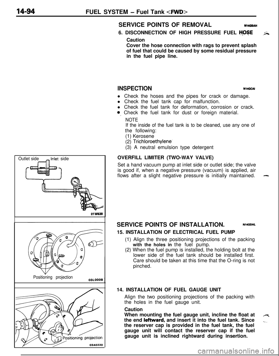
Outlet side_ Inlet side01
W838
Positioning projection
03A0220SERVICE POINTS OF REMOVALtilirro8AH
6. DISCONNECTION OF HIGH PRESSURE FUEL
H;OSECaution
Cover the hose connection with rags to prevent splash
of fuel that could be caused by some residual pressure
in the fuel pipe line.
INSPECTIONN14GCAll Check the hoses and the pipes for crack or damage.
l Check the fuel tank cap for malfunction.
l Check the fuel tank for deformation, corrosion or crack.
0,. Check the fuel tank for dust or foreign material.
NOTE
If the inside of the fuel tank is to be cleaned, use any one ofthe following:
(1) Kerosene
(2)
Trichloroethylene-(3) A neutral emulsion type detergent
OVERFILL LIMITER (TWO-WAY VALVE)
Set a hand vacuum pump at inlet side or outlet side; the valve
is good if, when a negative pressure (vacuum) is applied, air
flows after a slight negative pressure is initially maintained.
SERVICE POINTS OF INSTALLATION.
Nl4DDAL15. INSTALLATION OF ELECTRICAL FUEL PUMP
(1) Align the three positioning projections of the packing
with the holes in the fuel pump.
(2) When the fuel pump is installed, the holding bolt at the
lower side of the fuel tank should be installed first.
Care should be taken at this time that the O-ring is not
pinched.14. INSTALLATION OF FUEL GAUGE UNIT
Align the two positioning projections of the packing with
the holes in the fuel gauge unit.
Caution
When mounting the fuel gauge unit, incline the float at
the end leftward, and insert it into the fuel tank. Since
the reserver cap is provided in the fuel tank, the fuel
gauge unit will contact the reserver cap if the fuel
gauge unit is inclined rightward during insertion.
-
4
-,
Page 551 of 1216
FUEL SYSTEM - Fuel Tank
FUEL TANK
i. REMOVAL AND INSTALLATION
N140A-A
_-Pre-removal Operation
eDraining of the fuel.@Release of Residual Pressure from High
Pressure Fuel Hose(Refer to
P.14-44.)Post-installation Operation
*Measurement of Fuel Pressure(Refer to P.14-44, 52.)l .Supplving of the Fuel.
1-2 Nm825-35 Nm
‘*-*: ft-‘bs*
9-14 Nm- 7-10 ft.lbs.-9
-7
03AO262
15-20 Nm
11-14 ftlbs.Removal steps
1. Fuel tankcap2. Packing
3. Drain plug4. Return hose
5. Vapor hose
4*6. High pressure fuel hose
7. Fuel filler hose
8. Cable band9. Protector
10. Vapor pipe11. Vapor hose
l 4 12. Hole cover13. Self-locking nut
14. Fuel tank
15. Overfill limiter (Two-way valve)
l + 16. Fuel pump and fuel gauge unit assembly
17. Fuel filler neck
FyTEeverse the removal procedures to reinstall.(2) ~~ : Refer to “Service Points of RemoveI”.(3) l + : Refer to “Service Points of Installation”.(4) m : Non-reusable parts
Page 552 of 1216

14-98FUEL SYSTEM -Fuel Tank 01
W636
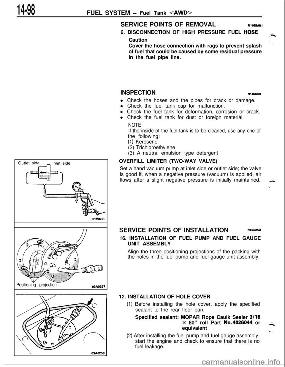
Positioning projection03AO257
\03A0256SERVICE POINTS OF REMOVAL
N14G6AHl6. DISCONNECTION OF HIGH PRESSURE FUEL
HGSECaution
Cover the hose connection with rags to prevent splash
of fuel that could be caused by some residual pressure
in the fuel pipe line.
INSPECTIONN14GCAHl Check the hoses and the pipes for crack or damage.
l Check the fuel tank cap for malfunction.
l Check the fuel tank for deformation, corrosion or crack.
l Check the fuel tank for dust or foreign material.
NOTE
If the inside of the fuel tank is to be cleaned, use any one ofthe following:
(1) Kerosene
(2) Trichloroethylene
(3) A neutral emulsion type detergent
OVERFILL LIMITER (TWO-WAY VALVE)
Set a hand vacuum pump at inlet side or outlet side; the valve
is good if, when a negative pressure (vacuum) is applied, air
flows after a slight negative pressure is initially maintained.
SERVICE POINTS OF INSTALLATION
N14GDAO16. INSTALLATION OF FUEL PUMP AND FUEL GAUGE
UNIT ASSEMBLY
Align the three positioning projections of the packing with
the holes in the fuel pump and fuel gauge unit assembly.
12. INSTALLATION OF HOLE COVER
) Before installing the hole cover, apply the specified
sealant to the rear floor pan.
Specified sealant: MOPAR Rope Caulk Sealer
3116
x 80” roll Part No.4026044 or
equivalent
!) After installing the fuel pump and fuel gauge assembly,
start the engine and check to ensure that there is no
fuel leakage.
Page 634 of 1216

17-24REAR SUSPENSION - Rear Suspension Assembly
1
II
brakeA022116. REMOVAL OF REAR SUSPENSION ASSEMBLY
(1) Supporting the rear suspension assembly with a trans-
mission jack, move it toward the rear (in the direction of
wtthe fuel tank).
c1(2) Gradually lower the transmission jack, avoiding contact
with the stabilizer bar and the propeller shaft.
Caution
1. Ensure that the propeller shaft does not bend
greatly.
2.Ensure that the liibro joint does not receive any
shock.
NOTEThe lowering of the rear suspension assembly from the
transmission jack requires three individuals due to the
amount of weight being handled (one on the differen-
tial, and one on either side of the lower arm).
(3) In order to protect the rear suspension assembly dust
shield, support the lower arm ball joint with a wooden
block.
INSPECTIONNl7GCAMl Check crossmember for cracks or other damage.
SERVICE POINTS OF INSTALLATIONN17GOAR -
8.INSTALLATION OF PROPELLER SHAFT INSTALLATIONBOLT AND NUT
Install the propeller shaft to the differential carrier, ensuringthat the mating marks are aligned.
3. INSTALLATION OF PARKING BRAKE CABLE END
NOTE
Connecting a parking brake cable end to parking brake lever
and prying up the parking brake lever, the installation of theother cable end will be easy.
’ice,
Page 1082 of 1216
23-38BODY - Fuel Tank Filler Door
FUEL TANK FILLER DOOR
REMOVAL AND INSTALLATIONN23JAA0
Pre-removal Operatione Removal of Rear Seat
(Refer to P.23-93.)0 Removal of Rear Side Trim, Quart-
er Trim and Scuff Plate.
(Refer to
P.23-85.)
Post-installation Operationl Installation of Rear Side Trim,
Quarter Trim and Scuff Plate
(Refer to
P.23-85.)0 Installation of Rear Seat
(Refer to P.23-93.)0 Fuel Filler Door Adjustment
(Refer to P.23-31.)
Removal stepsl C 1. Fuel filler door
2. Fuel filler door hook
3. Release handle cover
l + 4. Fuel filler door lock release handle
5. Fuel filler door lock release cable16A0462NOTE
(I 1 Reverse the removal procedures to reinstall.(2) l * : Refer to “Service Points of Installation”.
SERVICE POINTS OF INSTALLATION4.
APPLICATION OF GREASE TO FUEL FILLER DOOR LOCK
RELEASE HANDLE/l. FUEL FILLER DOORApply multipurpose grease to all moving parts.
Grease: MOPAR Multipurpose Grease Part No.
2932524 or equivalent