Page 352 of 1216

9-68ENGINE <1.8L Engine> - Piston and Connecting Rod
r-Size and maker marks
No. 1Barrel
faced
1
1 Size and maker marks
L
INo.2
ti2zza
Tapered
Barrelfaced
1 EN064
-1 No. 1 rina aarGap of
upper8. INSTALLATION OF
NO.2 PISTON RING/7. NO. 1
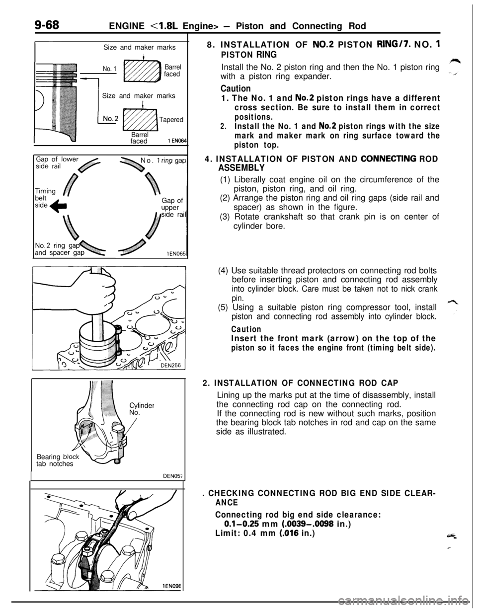
PISTON RINGInstall the No. 2 piston ring and then the No. 1 piston ring
with a piston ring expander.
Caution
1. The No. 1 and No.2 piston rings have a different
cross section. Be sure to install them in correct
positions.
2.Install the No. 1 and No.2 piston rings with the size
mark and maker mark on ring surface toward the
piston top.
4. INSTALLATION OF PISTON AND CONNECTlNG ROD
ASSEMBLY(1) Liberally coat engine oil on the circumference of the
piston, piston ring, and oil ring.
(2) Arrange the piston ring and oil ring gaps (side rail and
spacer) as shown in the figure.
(3) Rotate crankshaft so that crank pin is on center of
cylinder bore.
Bearing
bltab notches
DEN057(4) Use suitable thread protectors on connecting rod bolts
before inserting piston and connecting rod assembly
into cylinder block. Care must be taken not to nick crank
pin.(5) Using a suitable piston ring compressor tool, install
piston and connecting rod assembly into cylinder block.
Caution
Insert the front mark (arrow) on the top of the
piston so it faces the engine front (timing belt side).
2. INSTALLATION OF CONNECTING ROD CAPLining up the marks put at the time of disassembly, install
the connecting rod cap on the connecting rod.
If the connecting rod is new without such marks, position
the bearing block tab notches in rod and cap on the same
side as illustrated.
. CHECKING CONNECTING ROD BIG END SIDE CLEAR-
ANCE
Connecting rod big end side clearance:
0.1-0.25 mm (.0039-.0098 in.)
Limit: 0.4 mm (016 in.)
Page 634 of 1216

17-24REAR SUSPENSION - Rear Suspension Assembly
1
II
brakeA022116. REMOVAL OF REAR SUSPENSION ASSEMBLY
(1) Supporting the rear suspension assembly with a trans-
mission jack, move it toward the rear (in the direction of
wtthe fuel tank).
c1(2) Gradually lower the transmission jack, avoiding contact
with the stabilizer bar and the propeller shaft.
Caution
1. Ensure that the propeller shaft does not bend
greatly.
2.Ensure that the liibro joint does not receive any
shock.
NOTEThe lowering of the rear suspension assembly from the
transmission jack requires three individuals due to the
amount of weight being handled (one on the differen-
tial, and one on either side of the lower arm).
(3) In order to protect the rear suspension assembly dust
shield, support the lower arm ball joint with a wooden
block.
INSPECTIONNl7GCAMl Check crossmember for cracks or other damage.
SERVICE POINTS OF INSTALLATIONN17GOAR -
8.INSTALLATION OF PROPELLER SHAFT INSTALLATIONBOLT AND NUT
Install the propeller shaft to the differential carrier, ensuringthat the mating marks are aligned.
3. INSTALLATION OF PARKING BRAKE CABLE END
NOTE
Connecting a parking brake cable end to parking brake lever
and prying up the parking brake lever, the installation of theother cable end will be easy.
’ice,
Page 921 of 1216

AUTOMATIC TRANSAXLE - Transaxle Assemblv
-MB991 11312K513Pry bar
*Transaxle
llK611
SERVICE POINTS OF REMOVALN2llEAK
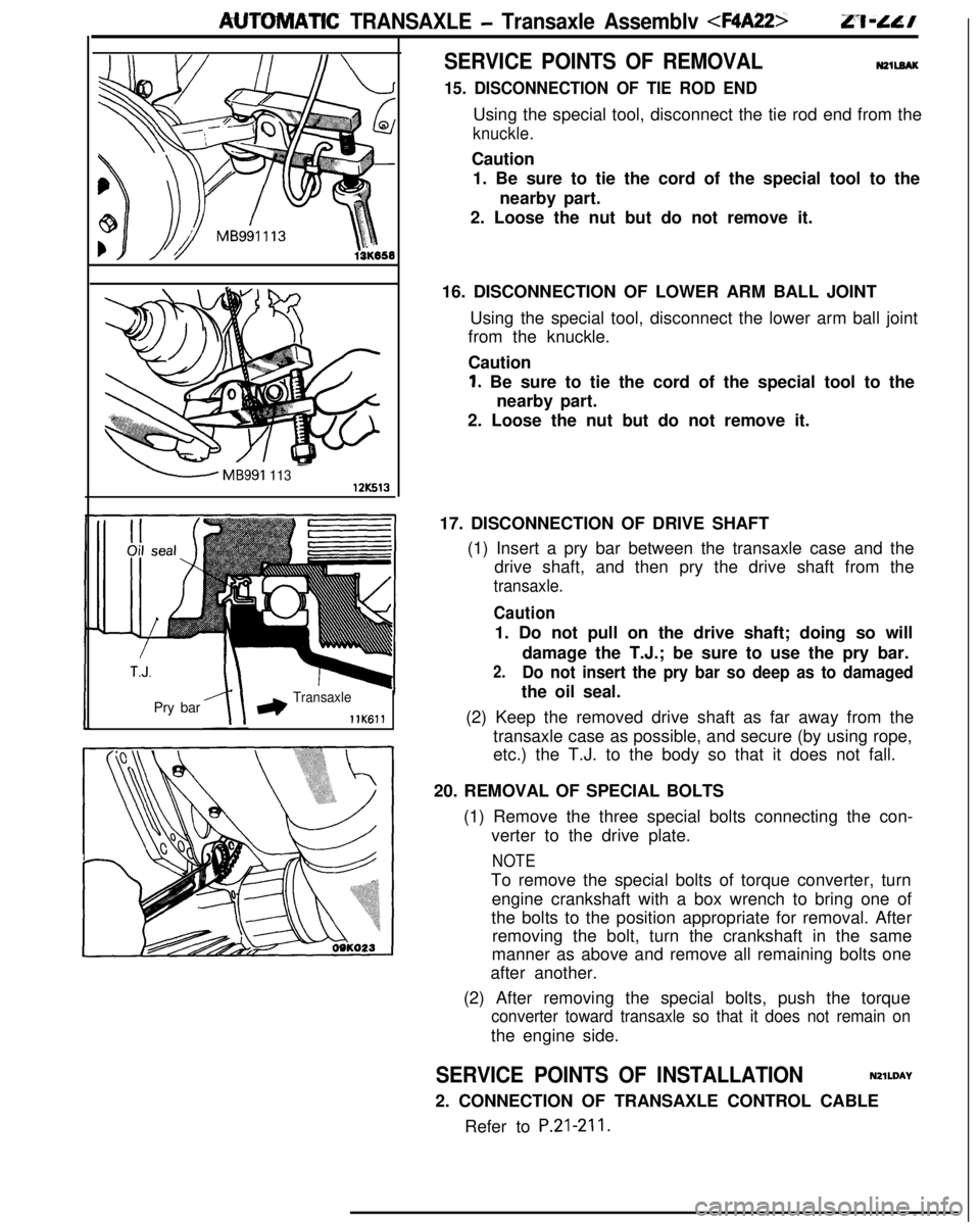
15. DISCONNECTION OF TIE ROD ENDUsing the special tool, disconnect the tie rod end from the
knuckle.Caution
1. Be sure to tie the cord of the special tool to the
nearby part.
2. Loose the nut but do not remove it.
16. DISCONNECTION OF LOWER ARM BALL JOINT
Using the special tool, disconnect the lower arm ball joint
from the knuckle.
Caution
1. Be sure to tie the cord of the special tool to the
nearby part.
2. Loose the nut but do not remove it.
17. DISCONNECTION OF DRIVE SHAFT
(1) Insert a pry bar between the transaxle case and the
drive shaft, and then pry the drive shaft from the
transaxle.
Caution1. Do not pull on the drive shaft; doing so will
damage the T.J.; be sure to use the pry bar.
2.Do not insert the pry bar so deep as to damagedthe oil seal.
(2) Keep the removed drive shaft as far away from the
transaxle case as possible, and secure (by using rope,
etc.) the T.J. to the body so that it does not fall.
20. REMOVAL OF SPECIAL BOLTS
(1) Remove the three special bolts connecting the con-
verter to the drive plate.
NOTETo remove the special bolts of torque converter, turn
engine crankshaft with a box wrench to bring one of
the bolts to the position appropriate for removal. After
removing the bolt, turn the crankshaft in the same
manner as above and remove all remaining bolts one
after another.
(2) After removing the special bolts, push the torque
converter toward transaxle so that it does not remain onthe engine side.
SERVICE POINTS OF INSTALLATIONN2lWAY
2. CONNECTION OF TRANSAXLE CONTROL CABLE
Refer to
P.21-211.