1991 MITSUBISHI ECLIPSE wheel bolt torque
[x] Cancel search: wheel bolt torquePage 52 of 1216

2-4FRONT SUSPENSION - Specifications
SERVICE SPECIFICATIONS;02CB-
ItemsVehicles with
1.8L Engine
2.0L DOHC Engine
Standard value
Camber14’230’5’+30’10’+30’
Caster2”20’ -t 30’2”24’ 3130’2”18’ f 30’
Toe-inmm (in.) Of3 (Ok.12)Of3 (Ok .12)Of3 (Ok.12)
Protruding length of stabilizer bar
mounting boltmm (in.) 16-18
(.63-.70)--Setting of T.J. boot lengthmm (in.)
L.H.75+3 (2.95f.12)80-+3 (3.15f.12)85_+3 (3.35k.12)
R.H.85f3 (3.35k.12)80+3 (3.15k.12)85f3 (3.35f.12)Lower arm ball joint starting
torqueNm (in.lbs.) 3-10 (26-87)3- 10 (26-87)3- 10 (26-87)
Stabilizer link ball joint starting
torqueNm (inlbs.) -1.7-3.2 (15-28)1.7-3.2 (15-28)
Crossmember bushings projection
mm (in.)
Bushing A
7.2-10.2 (.28-.40)7.2-10.2 (.28-.40)7.2-10.2 (.28-.40)
Bushing
B6.5-9.5 (.26-.37)6.5-9.5 (.26-.37)6.5-9.5 (.26-.37)
LimitHub end playmm (in.) 0.2
(.008) or less
Wheel bearing starting torque
(Hub starting torque)Nm
(in.lbs.) 1.8 (16) or less
TORQUE SPECIFICATIONSNO2CG.
ItemsDrive shaft nut
Tie rod end ball joint
Knuckle to ball joint
Knuckle to strut assembly
Strut top end nut
Strut mounting nut
upperCaliper assembly mounting bolt
Center bearing bracket
Front speed sensor bracket
Front toothed rotor
Stabilizer bar bracket to crossmember
Stabilizer link
Lower arm clamp to crossmember (nut)
Lower arm clamp to crossmember (bolt)
Lower arm to crossmember
Stay to crossmember
Front exhaust pipe to exhaust manifold
Turbo
Non-TurboFront exhaust pipe clamp
Crossmember to body
Front roll stopper bracket to centermember
Nmftlbs.
200-260144-188
24-3417-25
60-7243-52
1 IO-14080-101
60-7043-51
40-5029-39
80-10058-72
36-4626-33
9-14
7-109-14
7-10
30-4222-3035-4525-33
35-4725-34
80-I 0058-72
100-12072-87
70-8051-58
40-6029-43
30-4022-29
30-4022-29
100-12072-87
40-5029-36
Page 105 of 1216

REAR AXLE - Specifications
ItemsLimit
Rear axle total backlash
Drive gear
runoutRear wheel bearing end play
Differential gear backlashSpecifications
mm (in.) 5
(.2)mm (in.) 0.05
(.002)mm (in.) 0.8
(.031)mm (in.) 0.2
(.008)
TORQUE SPECIFICATIONS
ItemsNmft.lbs.
Drive shaft to companion flange55-65
40-47Axle shaft installation nut
160-220116-159Rear brake assembly installation bolts
50-6036-43
Rear speed sensor brackets9-14
7-10Differential carrier to crossmember
100-12072-87
Differential carrier to propeller shaft
30-3522-25
Differential carrier to differential support
member80- 10058-72
Differential support member to bolt
110-13080-94Drain plug
60-7043-51
Filler plug40-6029-43
Companion flange to drive pinion
160-220116-159
Bearing cap installation bolt
40-6029-43
Drive to differential case
gear80-9058-65
Cover to carrier
gear30-4222-30
LUBRICANTS
ItemsRear axle gear oilSpecified lubricantsQuantity
MOPAR Hypoid Gear Oil API classification
GL-5 or higher0.7 lit. (0.74 qts.Above
-23°C (-10°F) SAE 90, 85W-90, 8OW-90From
-34°C (-30°F) to -23°C (-10°F) SAE 8OW, 8OW-90Below
-34°C (-30°F) SAE 75WB.J. boot grease
D.O.J. boot greaseRepair kit grease90
g (3.2 dz.)Seal lip of outer bearingMOPAR Multi-Mileage Lubricant Part No.2525035 or equivalent As required
Trailing arm oil seal lip
Oil seal lip of side bearing
Washer of special tool
(M B990836)Oil seal lip of drive pinion
Differential companion
flange washer
SEALANTS AND ADHESIVES
..-
ItemsSpecified sealants and adhesivesIVent plug
Differential cover3M ATD Part
No.8661, 8663 or equivalent
Drive gear threaded holeMOPAR Part
No.4318031 or 4318032 or equivalent
Page 111 of 1216

REAR AXLE - Service Adjustment Procedures3-9
14A0521
IncorrectREAR WHEEL BEARING ROTATION SLIDING
RESISTANCE CHECKNOOFJAA
(1) Remove the drive shaft from the companion flange.
(2) Remove the brake pad or caliper assembly.
(3) Attach a spring balance to the hub bolt, then, pulling the
balance at a right angle to the hub bolt, measure the
rotation sliding resistance (rotation starting torque) to see
whether it is within the standard value.
Standard value: 12
N (2.6 Ibs.) [rotation starting tor-
que 0.7 Nm (6 in
Ibs.)] or less
(4) If the rotation starting torque exceeds the standard value,
check the tightening torque of the axle shaft companion
flange. If it is normal, replace the bearing.
LIMITED-SLIP DIFFERENTIAL CHECKNOJFIAA(1) Block the front wheels and move the shift lever to neutral.
(2) Completely release the parking brake.
(3) Jack up the rear wheels and place a rigid rack at the
specified part of the side sill.
(4) Disconnect the coupling of the differential and propeller
shaft.(5) When one wheel is slowly rotated, check whether or not
the wheel on the other side turns in the same direction.
(6) If it turns in the opposite direction, replace the viscous unit.
_--
Page 248 of 1216

6-18CLUTCH - Clutch Cover and Disc
I6CLO33
Clutch disc
T& assemblyClutch cover
6CLO26
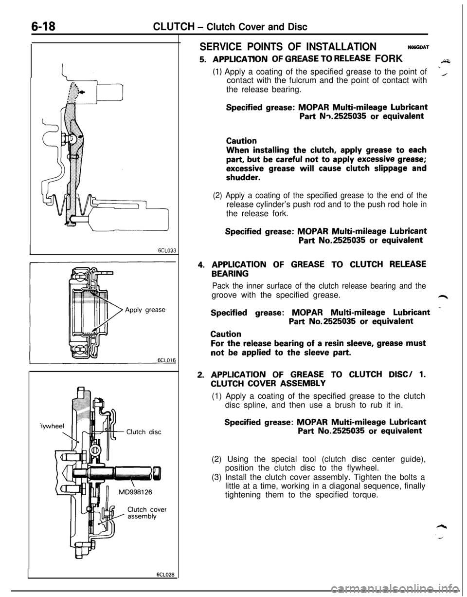
SERVICE POINTS OF INSTALLATIONNWGDAT
5. A,PPLlCATlONOF GREASE TO RELEASE FORKAi&
(1) Apply a coating of the specified grease to the point of
contact with the fulcrum and the point of contact withi(the release bearing.
Specified grease: MOPAR Multi-mileage Lubricant
Part Nq.2525035 or equivalentCautionWhen installing the
clutch, apply grease to each
part, but be careful not to apply excessive grease;
excessive grease will cause clutch slippage and
shudder.
(2) Apply a coating of the specified grease to the end of therelease cylinder’s push rod and to the push rod hole in
the release fork.
Specified grease: MOPAR Multi-mileage Lubricant
Part No.2525035 or equivalent
4. APPLICATION OF GREASE TO CLUTCH RELEASE
BEARING
Pack the inner surface of the clutch release bearing and thegroove with the specified grease.
L4r
Specified grease: MOPAR Multi-mileage Lubricant _
Part No.2525035 or equivalentCaution
For the release bearing of a resin sleeve, grease mustnot
be applied to the sleeve part.
2. APPLICATION OF GREASE TO CLUTCH DISC/ 1.
CLUTCH COVER ASSEMBLY
(1) Apply a coating of the specified grease to the clutch
disc spline, and then use a brush to rub it in.
Specified grease: MOPAR Multi-mileage Lubricant
Part No.2525035 or equivalent
(2) Using the special tool (clutch disc center guide),
position the clutch disc to the flywheel.
(3) Install the clutch cover assembly. Tighten the bolts a
little at a time, working in a diagonal sequence, finally
tightening them to the specified torque.
Page 302 of 1216

9-18ENGINE - Specifications
TORQUE SPECIFICATIONS
NO9CG-Items
Engine mount insulator nut (large)
(small)
Engine mount bracket nut or bolt
Transaxle mount insulator nut
Transaxle mount to body
Front roll stopper insulator nut
Front roll stopper bracket to centermember
Rear roll stopper insulator nut
Rear roll stopper bracket to centermember
Accelerator cable adjusting bolts
Fuel high pressure hose to delivery pipe
Ground cable to air intake manifold
Control wiring harness to air intake plenum
Power steering oil pump to bracket
Air conditioner to bracketcompressor
Exhaust pipe clamp bolt
Exhaust pipe to rubber hanger
Oil drain plug
panOil (bolts)
pan(nuts)VVater pulley
pump
Tensioner pulley bracket (air conditioner compressor)
Timing belt front coverCrankshaft sprocket
Camshaft sprocket
Timing belt “B” tensioner bolt
-eft engine support bracket3il switch
pressure3il unit
pressure gauge
Iii filter bracket
Iii cover
pumpqelief plug
‘lywheel or drive plate
ixhaust pipe bracket
support
‘rant roll stopper bracket
Iear roll stopper bracket‘rant engine bracket
support
:1.8L Engine>
Oil screen
Rocker cover
Camshaft bearing cap bolt (6 x 20)
(8 x 65)
Exhaust pipe to exhaust manifold
Intake manifold bolt
stay
Cylinder head bolt
Crankshaft pulley
Crankshaft damper pulleyNm
ftlbs.
60-8043-58
30-4022-29
50-6536-47
60-8043-58
40-5029-36
50-6536-47
40-5029-36
40-5029-36
40-5029-36
4-63-4
4-6
3-4
4-6
3-4
4-6
3-4
35-45
25-33
23-27
17-20
30-4022-29
10-157-l 135-45
25-33
6-84-6
5-73.5-5
8-106-7
23-27
17-20
10-127-9
110-13080-94
80-10058-72
15-2211-16
30-4222-308-126-9
8-126-9
15-2211-16
15-1811-13
40-5029-36
130-14094-101
30-4222-3055-75
40-54
110-13080-94
50-7036-51
18-2513-18
5-74-5
20-2714-2019-21
14-15
30-4022-29
18-2513-18
70-7551-5415-1811-13
15-1811-13
Page 417 of 1216

ENGINE <2.0L DOHC Engine>- Crankshaft, Flywheel and Drive Plate,91133
INSPECTIONNOSUHAD
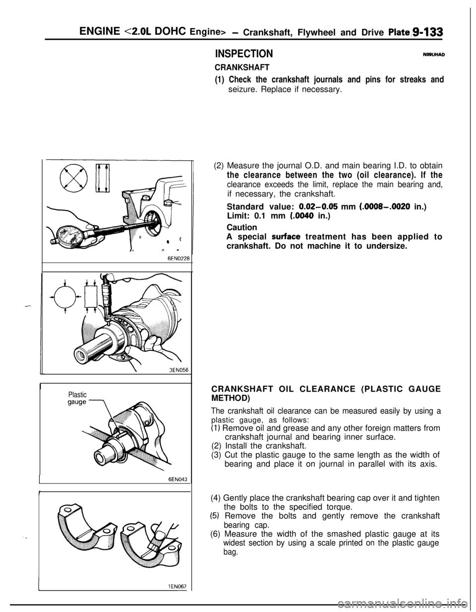
CRANKSHAFT(1) Check the crankshaft journals and pins for streaks and
seizure. Replace if necessary.
6EN0’228
\3EN056
Plastic
6EN043
. .
I1 EN067-(2) Measure the journal O.D. and main bearing I.D. to obtain
the clearance between the two (oil clearance). If the
clearance exceeds the limit, replace the main bearing and,if necessary, the crankshaft.
Standard value:
0.02-0.05 mm (.OOOS-.0020 in.)
Limit: 0.1 mm
(.0040 in.)
Caution
A special
surface treatment has been applied to
crankshaft. Do not machine it to undersize.
CRANKSHAFT OIL CLEARANCE (PLASTIC GAUGE
METHOD)
The crankshaft oil clearance can be measured easily by using aplastic gauge, as follows:
(1) Remove oil and grease and any other foreign matters from
crankshaft journal and bearing inner surface.
(2) Install the crankshaft.
(3) Cut the plastic gauge to the same length as the width of
bearing and place it on journal in parallel with its axis.
(4) Gently place the crankshaft bearing cap over it and tighten
the bolts to the specified torque.
(5) Remove the bolts and gently remove the crankshaft
bearing cap.(6) Measure the width of the smashed plastic gauge at its
widest section by using a scale printed on the plastic gauge
bag.
Page 612 of 1216

17-2REAR SUSPENSION
GENERAL SPECIFICATIONS
LN17CAA
ItemsVehicles with 1.8L EngineVehicles with 2.0L DOHC
Engine
jSuspension system
3-link, torsion axle with coil spring type
Coil spring
Wire dia.
x O.D. x free length
mm (in.) 10.1 x 105.1 x 336.510.2 x 105.2 x 316.5
(40 x 4.14 x 13.25)(40 x 4.14 x 12.46)
[Coil spring identification color]
[Light Blue
x 11[Orange x 11Spring constant
N/mm
(Ibs./in.) 20 (112.0)23 (128.8)
Shock absorber
TypeHydraulic, cylindrical, double-acting type
Max. length
mm (in.) 495 (19.5)485 (19.1)
Min. length
mm (in.) 315 (12.4)315 (12.4)
Strokemm (in.) 180 (7.1)170 (6.7)Damping force [at 0.3 m/set. (0.9
ft./set.)]
ExpansionN (Ibs.)800 (176)
ContractionN (Ibs.)300 (66)
Wheel bearing
TypeUnit ball bearing
SERVICE SPECIFICATIONS
Items
Standard valueToe-in (Left-right difference)
Camber
LimitWheel bearing end play
Rear hub rotary-sliding resistance
Rear hub rotary-sliding torque
NOTEToe-in and camber cannot be adjusted.mm (in.)
mm (in.)
N (Ibs.)
Nm
(ftlbs.)
TORQUE SPECIFICATIONS
Specifications
0+3 (Of.1 18)
-45’
f 30’
0.01 (004) or less
31
(7) or less
1.8
(1.30) or lessNI’ICB-A
ItemsNmft.lbs.
Wheel bearing nut
Shock absorber upper mounting nut
Shock absorber lower mounting nut
Lateral rod mounting nut (body side)
Lateral rod mounting bolt (axle beam side)
Trailing arm mounting bolt
Piston rod tightening nut
Brake hose and tube bracket mounting bolt
Caliper assembly mounting nut
Rear speed sensor mounting bolt
200-260
40-50
80- 100
80-100
100-120
100-120
20-2517-26
50-609-14144-188
29-36
58-72
58-72
72-87
72-87
14-18
12-19
36-43
I7-10
Nl7CGA
Page 613 of 1216

Special Tools/Troubleshooting/REAR SUSPENSION
SPECIAL TOOLN17DA.A
ToolNumberName1 Use1
L-451 4
Spring compressorRemoval and installation of the coil spring
bodyTROUBLESHOOTINGNI’IEA-A
Symptom
Squeaks or other
abnormal noiseProbable cause
Loose rear suspension installation bolts and nuts
Malfunction of shock absorber
Worn bushings
Remedy
Retighten
Replace
Poor rideExcessive tire inflation pressure
Malfunction of shock absorberWeak or broken springs
Adjust the pressure
Replace
Body tiltingWeak or deteriorated bushings
Weak or broken springs
Replace
SERVICE ADJUSTMENT PROCEDURES
REAR WHEEL ALIGNMENT INSPECTIONN17FAAC
The rear suspension assembly must be free of worn, loosen or
damaged parts prior to measurement of rear wheel alignment.
Standard value:
Toe-in (Left-right difference)
Of3 mm (Of.118 in.)
Camber-45’ + 30’
NOTEThe rear wheel alignment is set at the factory and cannot be
adjusted.If toe-in or camber is not within the standard value, replace
bent or damaged parts.
WHEEL BEARING END PLAY ADJUSTMENT,7FBA0
1.Inspect the play of the bearings while the vehicle is jacked
up and resting on floor jack.
2.Remove the hub cap and then release the parking brake.
3. Remove the caliper assembly and the brake disc.
4. Check the bearing’s end play.
Place a dial gauge against the hub surface; then move the
hub in the axial direction and check whether or not there isend play.
Limit: 0.01 mm
(.004 in.) or less
NOTE12AO531If the limit value is exceeded, the lock nut should be
tightened to the specified torque and check the end play
again.
5.Replace the rear hub bearing unit if an adjustment cannot
be made to within the limit.