Page 31 of 1216

INTRODUCTION AND MASTER TROUBLESH’OOTING .- Master ~pAi&oOti~31POOR FUEL MILEAGE
../, *,, /S./..‘, _I, #_.a,‘.rr?
Symptom
Poor fuel mileageProbable cause
Fuel leak
Air cleaner clogged.Ignition system problems
Reference page or remedy”Repair as necessary.
-8-169
IFuel injection system problems.I-ICompression too low.9-23
Tires improperly inflated.22-3
Clutch slips.6-4
Brakes drag.5-7I
NOISE
Symptom
NoiseProbable cause
Loose bolts and nuts.
Engine noiseReference page or remedy
Retighten as necessary
9-23
’
HARD STEERING
Symptom
Hard steeringProbable causeLoose power steering oil pump belt
Low fluid levelAir in power steering system
Low tire pressure
Reference page or remedy19-12
Replenish19-13
22-3
Excessive turning resistance of lower arm ballExcessively tightened of steering gear box
IImproper front wheel alignment2-8
Excessive turning resistance of tie-rod ballioint2-35
1 i-23.30
19-8.10Sticky flow control valve
Bent rack in steering gear box‘.19-4119-23.30
POOR RETURN OF STEERING WHEEL TO CENTERSymptom
1Probable causeIReference pageI
Poor return of steering wheel tocenterImproper front wheel alignment
2-8
Improper tire pressure22-3
Excessive tightened rack support cover19-23.30
I-- ~~~Damaged front wheel bearingI2-12I
Page 32 of 1216

32INTRODUCTION AND MASTER TROUBLESHOOTING - Master Troubleshooting
POOR RIDING
Symptom
Poor ridingProbable causeReference page or remedy
Improper tire pressure22-3
lmbalanced wheels
Improper front or rear wheel alignment
Malfunctioning shock absorberRepair
2-8,2917-3.20
Broken or worn stabilizer
Broken or worn coil spring2-29,37,42_ 17-8,32,35
Loose suspension securing bolt(s)Retighten
Worn lower arm bushing2-33
Worn suspension arm bushing2-33Y,’ ,>’
1 17-3.20I
ABNORMAL TIRE WEAR
Symptom
Abnormal tire wearProbable causeReference page
Improper front or rear wheel alignment2-8
Improper tire pressure22-3
Ilmbalanced wheelsIILoose wheel bearingsMalfunctioning shock absorber17-3
2-29
17-8,32
ROAD WANDER
Symptom
Road wanderProbable cause
Improper front or rear wheel alignmentReference page2-8
17-3.20Excessive play of steering wheel
19-7.10
Poor turning resistance of lower arm ball joint1 2-35I
Improper tire pressure22-3
Loose or worn lower arm bushing2-33
Loose or worn wheel bearings
Loose rack support cover in steering gear box
19-23,30
/-=..\
Page 33 of 1216

INTRODUCTION AND MASTER TROUBLESHOOTING - Master Troubleshooting
VEHICLE PULLS TO ONE SIDE
Symptom
Vehicle pulls to one sideProbable causeReference pageI
Improper front or rear wheel alignment
lmbalanced or worn tires
Uneven tire pressure2-817-3,2022-3
Excessive turning resistance of lower arm ball2-35
joint
Wheel bearing seizureReplace
Broken or weak coil spring2-29
Bent front axle drive shaft
2-15,3-13
Deformed lower arm2-35
STEERING WHEEL SHIMMY
SymptomSteering wheel shimmy
L
Probable cause
Improper front or rear wheel alignmentReference page or remedy2-8
17-3,20
Improper tire pressure22-3
lmbalanced wheelsReplace
Poor turning resistance of lower arm ball joint2-35
Excessive play of steering wheel
19-7,lO
Broken or weak front stabilizer2-33
Worn lower arm bushing2-33
Malfunctioning shock absorber2-29
17-8,32
Broken or weak coil spring
Wear, play, or seizure of wheel bearing
Wear, play, or seizure of drive shaft ball joint
Replace
2-15.3-13
BOTTOMING
I-SvmotomProbable cause1 Reference page or remedy[Bottoming
Overloaded vehicle
Broken or weak coil springMalfunctioning shock absorberCorrect2-29
l7-8,32
Page 316 of 1216

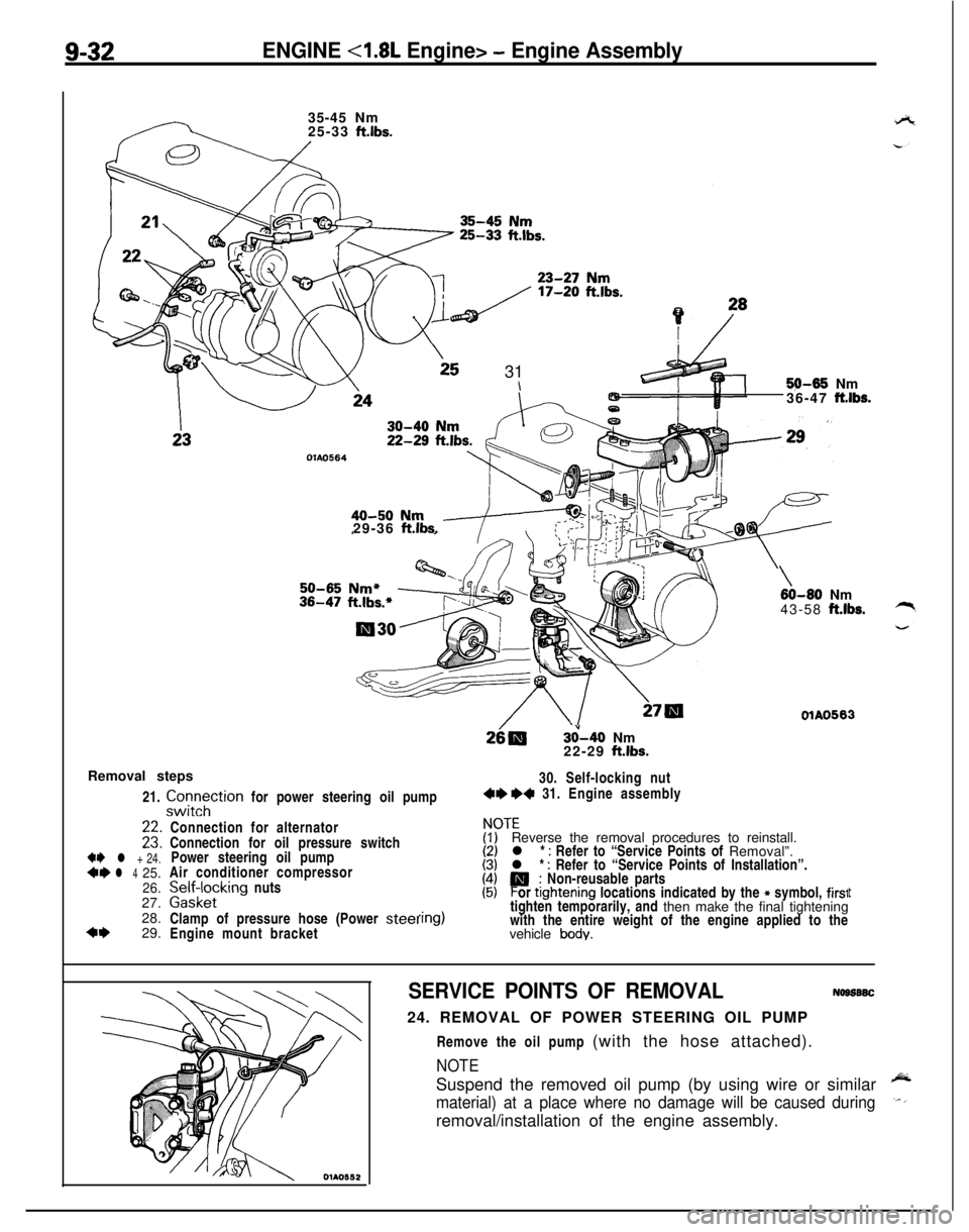
9-32ENGINE <1.8L Engine> - Engine Assembly35-45 Nm
25-33
ft.lbs.
25 31\5$M35 Nm
36-47 ft.lbs.
OlAO56429-36
ft.lbs.
3&40 Nm
22-29 ft.lbs.
Removal steps
21.
zztTtion for power steering oil pump30. Self-locking nut4e +4 31. Engine assembly
+e l + 24.*I)l 425.
26.27.
28.
4+29.
\60-80 Nm
43-58 ft.lbs.
OlAO563Connection for alternator
Connection for oil pressure switch
Power steering oil pump
Air conditioner compressor
palffz,cklng nuts
Clamp of pressure hose (Power
steelEngine mount bracket
ITEReverse the removal procedures to reinstall.
l *
: Refer to “Service Points of Removal”.
l * : Refer to “Service Points of Installation”.
P; Non-reusable parts
or ttghtening locations indicated by the * symbol, firs1tighten temporarily, and then make the final tightening
with the entire weight of the engine applied to the
vehicle
body.
t
SERVICE POINTS OF REMOVALNogs6SC24. REMOVAL OF POWER STEERING OIL PUMP
Remove the oil pump (with the hose attached).
NOTESuspend the removed oil pump (by using wire or similar
material) at a place where no damage will be caused duringremoval/installation of the engine assembly.
Page 366 of 1216

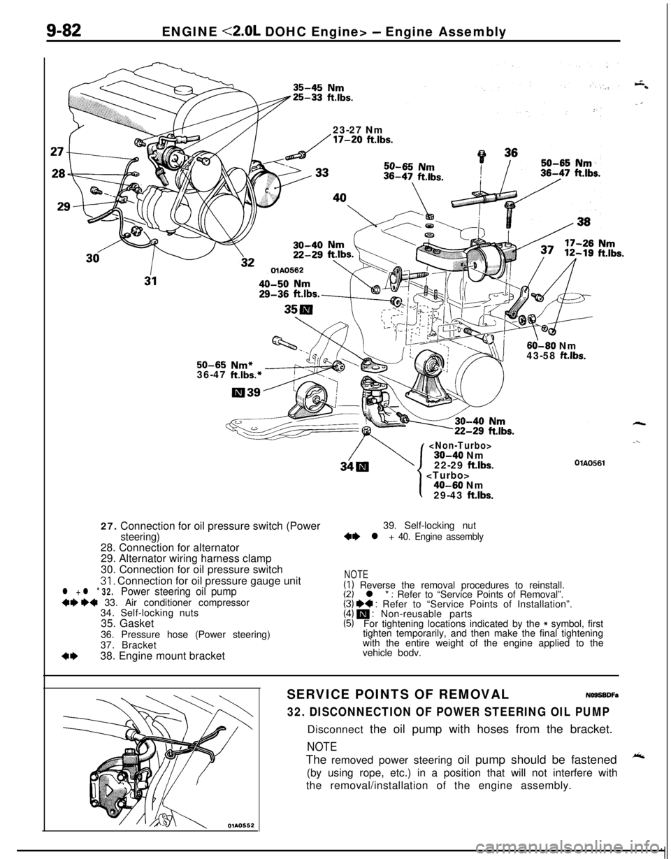
9-82ENGINE <2.0L DOHC Engine> - Engine Assembly
23-27 Nm
/17-20 ftlbs.
60-60 Nm
43-58 ft.lbs.50-65 Nm*36-47 ft.lbs.*27. Connection for oil pressure switch (Power
steering)28. Connection for alternator
29. Alternator wiring harness clamp
30. Connection for oil pressure switch
31, Connection for oil pressure gauge unitl + l * 32.Power steering oil pump+9 ~~ 33. Air conditioner compressor
34. Self-locking nuts
35. Gasket
36. Pressure hose (Power steering)
37. Bracket
4*38. Engine mount bracket
30-40 Nm
22-29 ftlbs.
.--
OlAO561
1
I40-60 Nm
29-43 ft.lbs.39. Self-locking nut
+e l + 40. Engine assembly
NOTE(I) Reverse the removal procedures to reinstall.(2) l * : Refer to “Service Points of Removal”.(3) I)+ : Refer to “Service Points of Installation”.(4) m : Non-reusable parts(5)For tightening locations indicated by the * symbol, first
tighten temporarily, and then make the final tightening
with the entire weight of the engine applied to the
vehicle bodv.
SERVICE POINTS OF REMOVALNOSSBDFa
32. DISCONNECTION OF POWER STEERING OIL PUMPDisconnect the oil pump with hoses from the bracket.
NOTEThe removed power steering oil pump should be fastened
A(by using rope, etc.) in a position that will not interfere with
the removal/installation of the engine assembly.
Page 410 of 1216

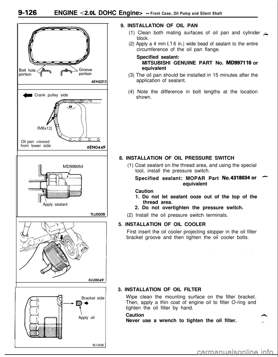
9-126ENGINE <2.0L DOHC Engine>- Front Case, Oil Pump and Silent Shaft
6EN0213
w Crank pulley side
Oil pan
from lower side
‘- Apply sealant7LUOOO0
6LUOO49 tBracket side
-----Be
\Apply oil9. INSTALLATION OF OIL PAN
(1) Clean both mating surfaces of oil pan and cylinder
+
block.
(2) Apply a 4 mm (.I 6 in.) wide bead of sealant to the entirecircumference of the oil pan flange.
Specified sealant:
MITSUBISHI GENUINE PART No.
MD9971 10 or
equivalent
(3) The oil pan should be installed in 15 minutes after the
application of sealant.
(4) Note the difference in bolt lengths at the location
shown.8. INSTALLATION OF OIL PRESSURE SWITCH
(1) Coat sealant on the thread area, and using the special
tool, install the pressure switch.
Specified sealant: MOPAR Part No.4318034
orequivalent
Caution
1. Do not let sealant ooze out of the top of the
thread area.
2. Do not overtighten the pressure switch.
(2) Install the oil pressure switch terminals.
5. INSTALLATION OF OIL COOLER
First insert the oil cooler projecting stopper in the oil filter
bracket groove and then tighten the oil cooler bolts.lu3. INSTALLATION OF OIL FILTER
Wipe clean the mounting surface on the filter bracket.
Then, apply a thin coat of engine oil to filter O-ring and
tighten the oil filter by hand.
Caution
-.Never use a wrench to tighten the oil filter.
-i
16LUO26
Page 613 of 1216

Special Tools/Troubleshooting/REAR SUSPENSION - Service Adjujltment Procedures
SPECIAL TOOLN17DA.A
ToolNumberName1 Use1
L-451 4
Spring compressorRemoval and installation of the coil spring
bodyTROUBLESHOOTINGNI’IEA-A
Symptom
Squeaks or other
abnormal noiseProbable cause
Loose rear suspension installation bolts and nuts
Malfunction of shock absorber
Worn bushings
Remedy
Retighten
Replace
Poor rideExcessive tire inflation pressure
Malfunction of shock absorberWeak or broken springs
Adjust the pressure
Replace
Body tiltingWeak or deteriorated bushings
Weak or broken springs
Replace
SERVICE ADJUSTMENT PROCEDURES
REAR WHEEL ALIGNMENT INSPECTIONN17FAAC
The rear suspension assembly must be free of worn, loosen or
damaged parts prior to measurement of rear wheel alignment.
Standard value:
Toe-in (Left-right difference)
Of3 mm (Of.118 in.)
Camber-45’ + 30’
NOTEThe rear wheel alignment is set at the factory and cannot be
adjusted.If toe-in or camber is not within the standard value, replace
bent or damaged parts.
WHEEL BEARING END PLAY ADJUSTMENT,7FBA0
1.Inspect the play of the bearings while the vehicle is jacked
up and resting on floor jack.
2.Remove the hub cap and then release the parking brake.
3. Remove the caliper assembly and the brake disc.
4. Check the bearing’s end play.
Place a dial gauge against the hub surface; then move the
hub in the axial direction and check whether or not there isend play.
Limit: 0.01 mm
(.004 in.) or less
NOTE12AO531If the limit value is exceeded, the lock nut should be
tightened to the specified torque and check the end play
again.
5.Replace the rear hub bearing unit if an adjustment cannot
be made to within the limit.
Page 629 of 1216
REAR SUSPENSION - Suecial TooWTroubleshootina
pnng compressor
TROUBLESHOOTINGNIlEA-6
Symptom
Squeaks or other
abnormal noiseProbable causeRemedyLoose rear suspension installation bolts and nuts Retighten
Malfunction of shock absorber
Worn bushings
Replace
Upper arms and/or lower arms deformed or
damaged
Poor ride
Body tiltingTrailing arms deformed or damaged
Crossmember deformed or damagedExcessive tire inflation pressure
Malfunction of shock absorber
Weak or broken springs
Stabilizer bar and/or stabilizer link deformed or
damaged
Weak or deteriorated bushings
Weak or broken springs
Upper arms and/or lower arms deformed or
damaged
Trailing arms deformed or damaged
Crossmember deformed or damagedAdjust the pressure
Replace
Replace