1991 MITSUBISHI ECLIPSE fuel pressure
[x] Cancel search: fuel pressurePage 31 of 1216

INTRODUCTION AND MASTER TROUBLESH’OOTING .- Master ~pAi&oOti~31POOR FUEL MILEAGE
../, *,, /S./..‘, _I, #_.a,‘.rr?
Symptom
Poor fuel mileageProbable cause
Fuel leak
Air cleaner clogged.Ignition system problems
Reference page or remedy”Repair as necessary.
-8-169
IFuel injection system problems.I-ICompression too low.9-23
Tires improperly inflated.22-3
Clutch slips.6-4
Brakes drag.5-7I
NOISE
Symptom
NoiseProbable cause
Loose bolts and nuts.
Engine noiseReference page or remedy
Retighten as necessary
9-23
’
HARD STEERING
Symptom
Hard steeringProbable causeLoose power steering oil pump belt
Low fluid levelAir in power steering system
Low tire pressure
Reference page or remedy19-12
Replenish19-13
22-3
Excessive turning resistance of lower arm ballExcessively tightened of steering gear box
IImproper front wheel alignment2-8
Excessive turning resistance of tie-rod ballioint2-35
1 i-23.30
19-8.10Sticky flow control valve
Bent rack in steering gear box‘.19-4119-23.30
POOR RETURN OF STEERING WHEEL TO CENTERSymptom
1Probable causeIReference pageI
Poor return of steering wheel tocenterImproper front wheel alignment
2-8
Improper tire pressure22-3
Excessive tightened rack support cover19-23.30
I-- ~~~Damaged front wheel bearingI2-12I
Page 302 of 1216

9-18ENGINE - Specifications
TORQUE SPECIFICATIONS
NO9CG-Items
Engine mount insulator nut (large)
(small)
Engine mount bracket nut or bolt
Transaxle mount insulator nut
Transaxle mount to body
Front roll stopper insulator nut
Front roll stopper bracket to centermember
Rear roll stopper insulator nut
Rear roll stopper bracket to centermember
Accelerator cable adjusting bolts
Fuel high pressure hose to delivery pipe
Ground cable to air intake manifold
Control wiring harness to air intake plenum
Power steering oil pump to bracket
Air conditioner to bracketcompressor
Exhaust pipe clamp bolt
Exhaust pipe to rubber hanger
Oil drain plug
panOil (bolts)
pan(nuts)VVater pulley
pump
Tensioner pulley bracket (air conditioner compressor)
Timing belt front coverCrankshaft sprocket
Camshaft sprocket
Timing belt “B” tensioner bolt
-eft engine support bracket3il switch
pressure3il unit
pressure gauge
Iii filter bracket
Iii cover
pumpqelief plug
‘lywheel or drive plate
ixhaust pipe bracket
support
‘rant roll stopper bracket
Iear roll stopper bracket‘rant engine bracket
support
:1.8L Engine>
Oil screen
Rocker cover
Camshaft bearing cap bolt (6 x 20)
(8 x 65)
Exhaust pipe to exhaust manifold
Intake manifold bolt
stay
Cylinder head bolt
Crankshaft pulley
Crankshaft damper pulleyNm
ftlbs.
60-8043-58
30-4022-29
50-6536-47
60-8043-58
40-5029-36
50-6536-47
40-5029-36
40-5029-36
40-5029-36
4-63-4
4-6
3-4
4-6
3-4
4-6
3-4
35-45
25-33
23-27
17-20
30-4022-29
10-157-l 135-45
25-33
6-84-6
5-73.5-5
8-106-7
23-27
17-20
10-127-9
110-13080-94
80-10058-72
15-2211-16
30-4222-308-126-9
8-126-9
15-2211-16
15-1811-13
40-5029-36
130-14094-101
30-4222-3055-75
40-54
110-13080-94
50-7036-51
18-2513-18
5-74-5
20-2714-2019-21
14-15
30-4022-29
18-2513-18
70-7551-5415-1811-13
15-1811-13
Page 308 of 1216
9-24ENGINE - Service Adjustment Procedures
ENGINE 4.8L Engine>
SERVICE ADJUSTMENT PROCEDURES -
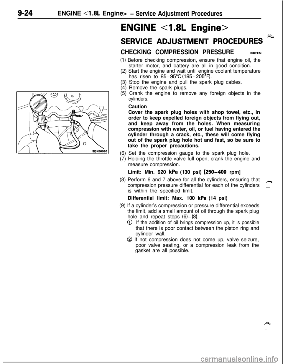
CHECKING COMPRESSION PRESSURENOSFFAI
(1) Before checking compression, ensure that engine oil, the
starter motor, and battery are all in good condition.
(2) Start the engine and wait until engine coolant temperature
has risen to
85-95°C (185-205°F).
(3) Stop the engine and pull the spark plug cables.
(4) Remove the spark plugs.
(5) Crank the engine to remove any foreign objects in the
cylinders.Caution
Cover the spark plug holes with shop towel, etc., in
order to keep expelled foreign objects from flying out,
and keep away from the holes. When measuring
compression with water, oil, or fuel having entered the
cylinder through a crack, etc., these will come flying
out of the spark plug hole hot and fast, so be sure to
take the proper precautions.
(6) Set the compression gauge to the spark plug hole.
(7) Holding the throttle valve full open, crank the engine and
measure compression.
Limit: Min. 920
kPa (130 psi) [250-400 rpm]
(8) Perform 6 and 7 above for all the cylinders, ensuring that
compression pressure differential for each of the cylinders
/Iis within the specified limit.
__Differential limit: Max. 100
kPa (14 psi)
(9) If a cylinder’s compression or pressure differential exceeds
the limit, add a small amount of oil through the spark plug
hole and repeat steps (6)-(8).
0If the addition of oil brings compression up, it is possiblethat there is poor contact between the piston ring and
cylinder wall.
@ If not compression does not come up, valve seizure,
poor valve seating, or a compression leak from the
gasket are all possible.
/y
-
Page 315 of 1216
ENGINE <1.8L Engine> - Engine Assembly9-31
ENGINE ASSEMBLY
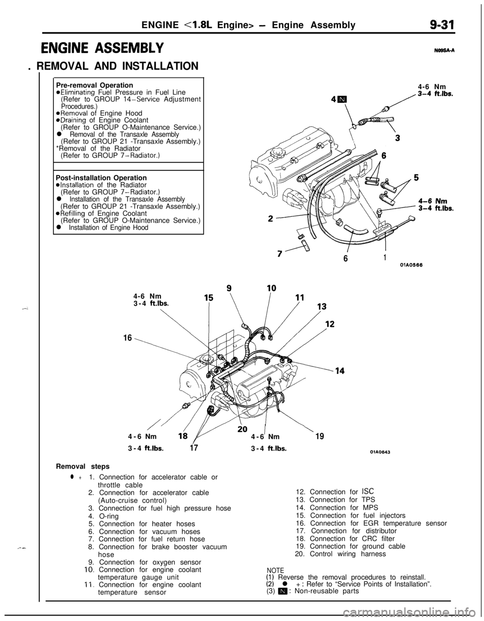
. REMOVAL AND INSTALLATION
N69SA-APre-removal Operation
@Eliminating Fuel Pressure in Fuel Line
(Refer to GROUP 14-Service AdjustmentProcedures.)@Removal of Engine HoodeDraining of Engine Coolant
(Refer to GROUP O-Maintenance Service.)
l Removal of the Transaxle Assembly(Refer to GROUP 21 -Transaxle Assembly.)
*Removal of the Radiator
(Refer to GROUP 7-Radiator.)
Post-installation Operation
@Installation of the Radiator
(Refer to GROUP 7-Radiator.)
l Installation of the Transaxle Assembly(Refer to GROUP 21 -Transaxle Assembly.)
@Refilling of Engine Coolant
(Refer to GROUP O-Maintenance Service.)
l Installation of Engine Hood4-6 Nm
“7
/61OlA05664-6 Nm
3-4
ft.lbs.
\
16
/io1\4-6Nm164-6Nm193-4ft.lbs.
173-4ft.lbs.OlA0643Removal steps
l +1. Connection for accelerator cable or
throttle cable
2. Connection for accelerator cable
(Auto-cruise control)
3. Connection for fuel high pressure hose
4. O-ring
5. Connection for heater hoses
6. Connection for vacuum hoses
7. Connection for fuel return hose
8. Connection for brake booster vacuum
hose
9. Connection for oxygen sensor
10. Connection for engine coolant
temperature gauge unit
11. Connection for engine coolant
temperature sensor12. Connection for
ISC13. Connection for TPS
14. Connection for MPS
15. Connection for fuel injectors
16. Connection for EGR temperature sensor
17. Connection for distributor
18. Connection for CRC filter
19. Connection for ground cable
20. Control wiring harness
NOTE(1) Reverse the removal procedures to reinstall.(2) l + : Refer to “Service Points of Installation”.
(3) m : Non-reusable parts
Page 320 of 1216
9-36ENGINE
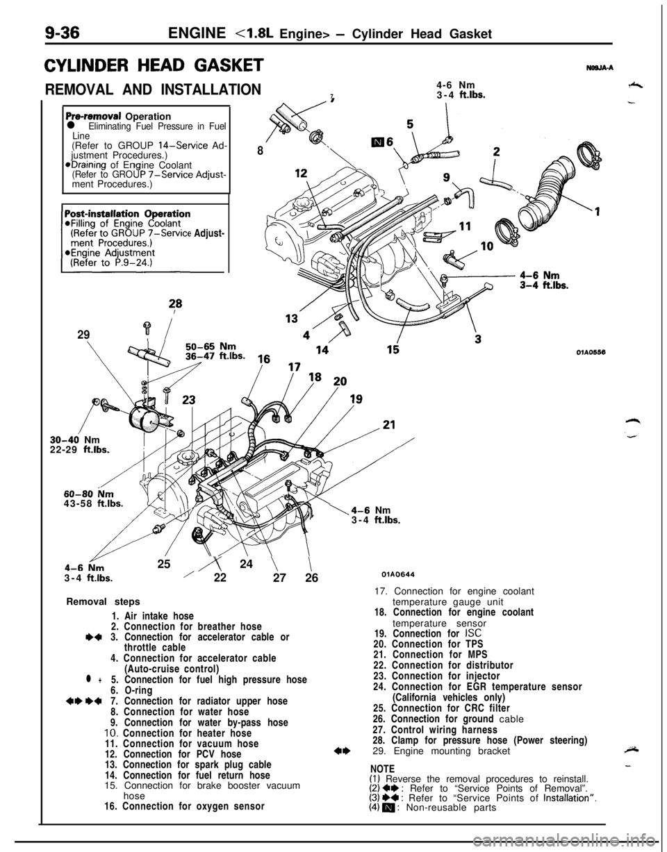
CYLINDER HEAD GASKET
REMOVAL AND INSTALLATION4-6 Nm
73-4 ft.lbs.
NWJA-A
Pre-removal Operationl Eliminating Fuel Pressure in Fuel
Line(Refer to GROUP
14-Service Ad-
justment Procedures.)*Draining of En
ine Coolant
(Refer to GRO9P -/-Service Adjust-ment Procedures.)
(Refer to GROUP
7-Service Adjust-~~~~~~~n
?*
29?i
8
30-46 Nm
22-29 ft.lbs.
60-80 ium43-58 ftlbs.25
iy 24 \\3-4
ftlbs./2227 26
Removal steps
1. Air intake hose
2. Connection for breather hose
I)43. Connection for accelerator cable or
throttle cable
4. Connection for accelerator cable
(Auto-cruise control)
l +5. Connection for fuel high pressure hose
6. O-ring
+e W7. Connection for radiator upper hose
8. Connection for water hose
9. Connection for water by-pass hose
10. Connection for heater hose
11. Connection for vacuum hose
12. Connection for PCV hose
13. Connection for spark plug cable
14. Connection for fuel return hose
15. Connection for brake booster vacuum
hose
16. Connection for oxygen sensor
1\4-6 Nm
3-4 ftlbs.
OlAO556
QlAO64417. Connection for engine coolant
temperature gauge unit
18. Connection for engine coolant
temperature sensor
19. Connection for
ISC20. Connection for TPS
21. Connection for MPS
22. Connection for distributor
23. Connection for injector
24. Connection for EGR temperature sensor
(California vehicles only)
25. Connection for CRC filter
26. Connection for ground cable
27. Control wiring harness
28. Clamp for pressure hose (Power steering)
29. Engine mounting bracket
NOTE
(I) Reverse the removal procedures to reinstall.(2) Ce : Refer to “Service Points of Removal”.(3) ++ : Refer to “Service Points of Installation”.(4) m : Non-reusable parts
Page 324 of 1216

ENGINE <1.8L Engine> - Cylinder Head Gasket
OlAOlO:Intake sideFront of engine
I,Exhaust side
01R0390
4pply
sealant 1Mating marks
.,
iighDelivery pipe3ressureloseO-ring03Aoo79(2) Using the special tool, tighten the bolts in the
ordershown in two or three steps.
a-2
31. APPLICATION OF SEALANT TO SEMI-CIRCULAR PACK-ING
Apply a coating of the specified sealant to the semi-circularpacking and the cylinder head top surfaces.
/LSpecified sealant: MOPAR Part No.4318034 or equiva-
_ ‘-lent
7.INSTALLATION OF RADIATOR UPPER HOSE
Align the mating marks (of the radiator hose and hose
clamp), and then, while applying force in the direction of
the arrow in the illustration, set the hose clamp to the
trace marks (on the hose) remaining from the prior
connection.
Caution
Be sure to install the hose clamp at the trace marks (onthe hose) remaining from the prior connection.
5. CONNECTION OF FUEL HIGH PRESSURE HOSE
When connecting the fuel high-pressure hose to the
delivery pipe, apply a coating of gasoline to the hose union,and insert so that the O-ring is not damaged.
3. INSTALLATION OF ACCELERATOR CABLE OR
THROT- +TLE CABLE CONNECTION
Refer to GROUP
14-Service Adjustment Procedures.
Page 358 of 1216
9-74ENGINE <2.0L DOHC Engine>- Service Adjustment Procedures
ENGINE <2.0L DOHC Engine>
SERVICE ADJUSTMENT PROCEDURES pi
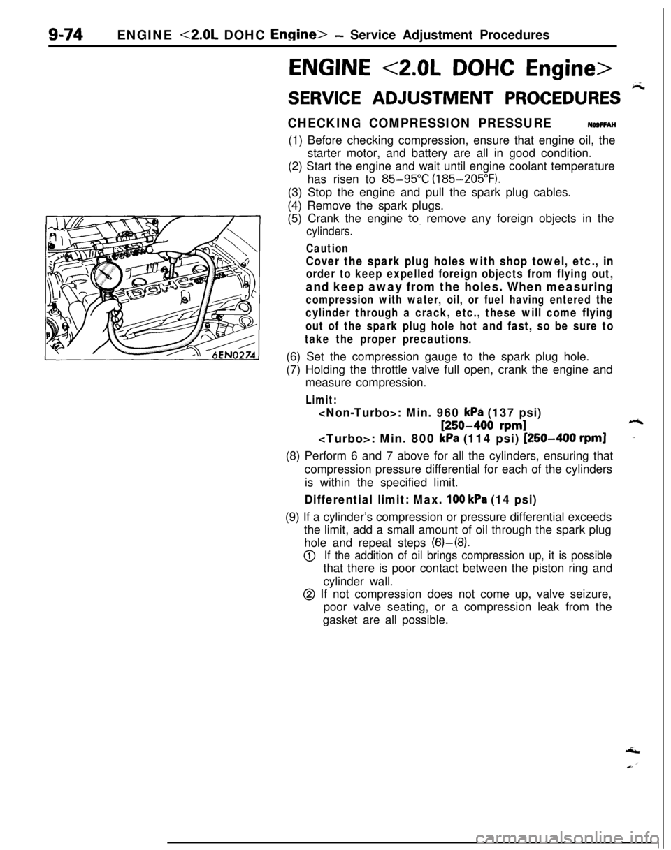
CHECKING COMPRESSION PRESSURENOSFFAH(1) Before checking compression, ensure that engine oil, the
starter motor, and battery are all in good condition.
(2) Start the engine and wait until engine coolant temperature
has risen to
85-95°C (185-205°F).
(3) Stop the engine and pull the spark plug cables.
(4) Remove the spark plugs.
(5) Crank the engine
to. remove any foreign objects in the
cylinders.
Caution
Cover the spark plug holes with shop towel, etc., in
order to keep expelled foreign objects from flying out,and keep away from the holes. When measuring
compression with water, oil, or fuel having entered the
cylinder through a crack, etc., these will come flying
out of the spark plug hole hot and fast, so be sure to
take the proper precautions.(6) Set the compression gauge to the spark plug hole.
(7) Holding the throttle valve full open, crank the engine and
measure compression.
Limit:
[250-400 rpm]6
kPa (114 psi) [250-400 rpml-(8) Perform 6 and 7 above for all the cylinders, ensuring that
compression pressure differential for each of the cylinders
is within the specified limit.
Differential limit: Max. 100 kPa (14 psi)(9) If a cylinder’s compression or pressure differential exceeds
the limit, add a small amount of oil through the spark plug
hole and repeat steps (6)-(8).
@If the addition of oil brings compression up, it is possiblethat there is poor contact between the piston ring and
cylinder wall.
@ If not compression does not come up, valve seizure,
poor valve seating, or a compression leak from the
gasket are all possible.‘I
Page 365 of 1216
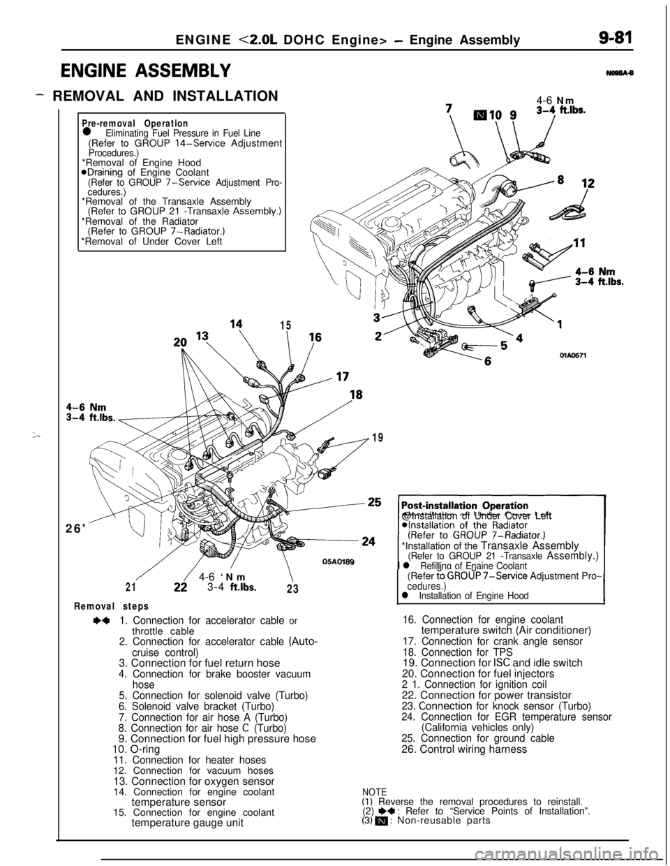
ENGINE <2.0L DOHC Engine> - Engine Assembly
ENGINE ASSEMBLY
- REMOVAL AND INSTALLATION
;-
Pre-removal Operationl Eliminating Fuel Pressure in Fuel Line(Refer to GROUP 14-Service AdjustmentProcedures.)*Removal of Engine Hood
@Draining of Engine Coolant(Refer to GROUP 7-Service Adjustment Pro-
cedures.)*Removal of the Transaxle Assembly
(Refer to GROUP 21 -Transaxle Assembly.)
*Removal of the Radiator
(Refer to GROUP 7-Radiator.)
*Removal of Under Cover Left
26'
15
I4-6 Nm\I /MAO571
19@Installation of Under Cover Left
*Installation of the Transaxle Assembly
(Refer to GROUP 21 -Transaxle Assembly.)
I l Refilling of Enaine Coolant
/22/ 4-6 ‘Nm\213-4 ftlbs.23
Removal steps
~~1. Connection for accelerator cable orthrottle cable
2. Connection for accelerator cable (Auto-
cruise control)3. Connection for fuel return hose
4. Connection for brake booster vacuum
hose
5. Connection for solenoid valve (Turbo)
6. Solenoid valve bracket (Turbo)
7. Connection for air hose A (Turbo)
8. Connection for air hose
C (Turbo)9. Connection for fuel high pressure hose
10. O-ring11. Connection for heater hoses12. Connection for vacuum hoses
13. Connection for oxygen sensor
14. Connection for engine coolant
temperature sensor
15. Connection for engine coolant
temperature gauge unit(Refer
t’o GROUP 7-Service Adjustment Pro-cedures.)l Installation of Engine Hood‘I
16. Connection for engine coolanttemperature switch (Air conditioner)
17. Connection for crank angle sensor
18. Connection for TPS19. Connection for
ISC and idle switch
20. Connection for fuel injectors
2 1. Connection for ignition coil22. Connection for power transistor
23. Connection for knock sensor (Turbo)
24. Connection for EGR temperature sensor
(California vehicles only)
25. Connection for ground cable26. Control wiring harness
NOTE(I) Reverse the removal procedures to reinstall.
(2) e+ : Refer to “Service Points of Installation”.(3) m : Non-reusable parts