1991 MITSUBISHI ECLIPSE fuel pressure
[x] Cancel search: fuel pressurePage 439 of 1216

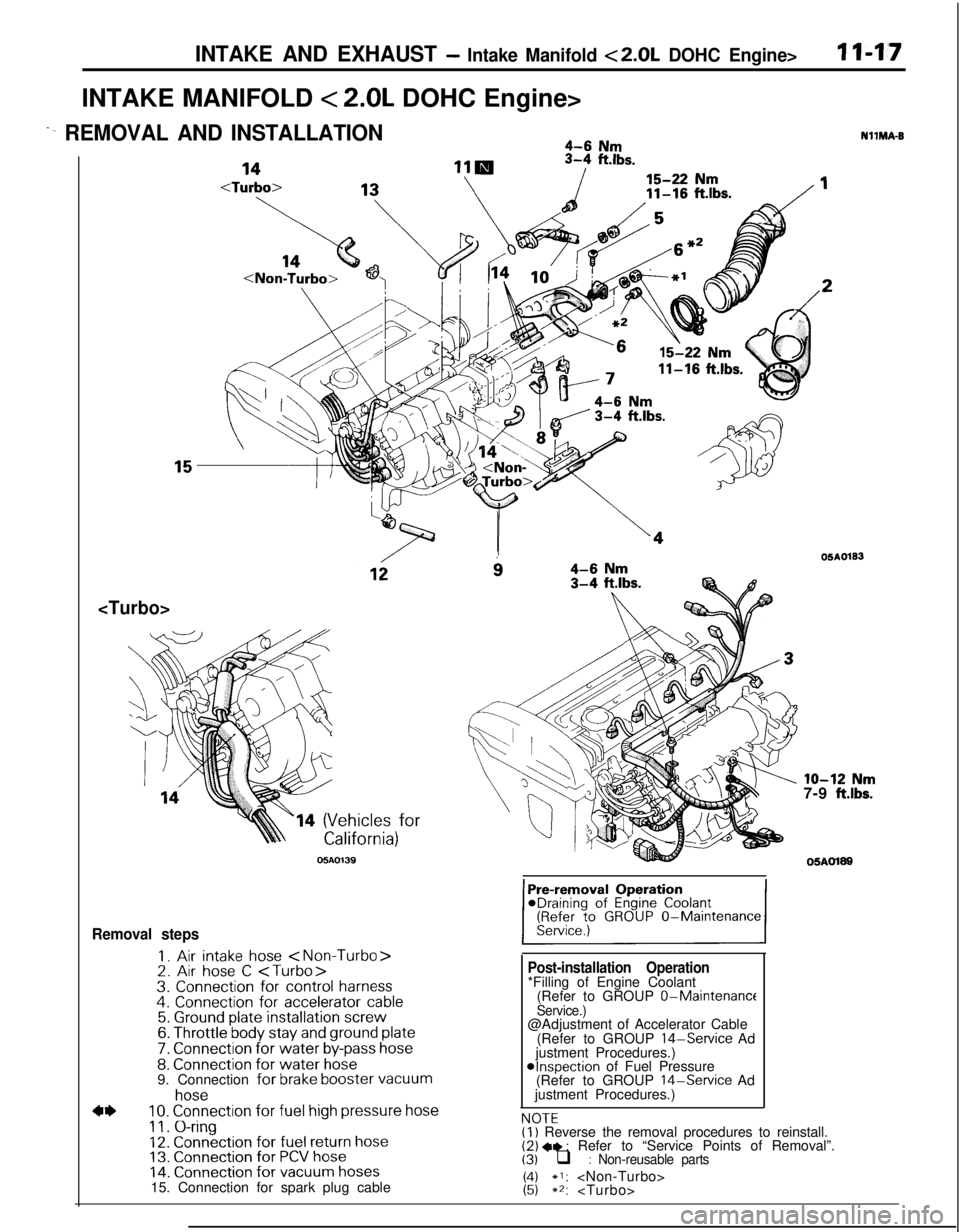
INTAKE AND EXHAUST - Intake Manifold <2.0L DOHC Engine>I I-1.7INTAKE MANIFOLD
< 2.0L DOHC Engine>
^- REMOVAL AND INSTALLATION4-6 Nm
ft.lbs.
14 (Vehicles for
05AO139
i34-6 Nm3-4 ftlbs.
Removal steps
I. Air intake hose
7. Connection for water by-pass hose8. Connection for water hose9. Connection for brake booster vacuum
4*
hose10. Connection for fuel high pressure hose
11. O-ring12. Connection for fuel return hose13. Connection for PCV hose14. Connection for vacuum hoses15. Connection for spark plug cable
Post-installation Operation*Filling of Engine Coolant
(Refer to GROUP 0-Maintenance
Service.)@Adjustment of Accelerator Cable
(Refer to GROUP
14-Service Ad
justment Procedures.)
@Inspection of Fuel Pressure
(Refer to GROUP 14-Service Ad
justment Procedures.)
NOTFNllMA-B
OSAO133
lo-12 Nm7-9 ft.lbs.
05AOl89
,.-.-(I) Reverse the removal procedures to reinstall.(2) +e : Refer to “Service Points of Removal”.(3) q : Non-reusable parts
1:;*I:
Page 440 of 1216

11-18INTAKE AND EXHAUST - Intake Manifold < 2.0L DOHC Engine>
10-27 Nm14-20 ft.lbs.
18hIO-13 Nm
7-9
ft.lbs.15-22 Nm11-16
ft.lbs.IO-12 Nm
7-9
ftlbs.05A0197
15-22 Nm
11-16
ftlbs.
wi2” vlo-12 Nm
7-9 ftlbs.25-30 Nm
18-22
ft.lbs.
24
\‘27
28lll
Removal steps
+e l + 16. Delivery pipe, fuel injector and pressureregulator17. Insulator18. Insulator19. Intake manifold stay
20. Intake manifold21. Intake manifold gasket22. Ignition coil23. Power transistor unit24. EGR valve25. Gasket26. EGR temperature sensor
29. Connection for control harness
30. Throttle body31. Gasket
NOTE(I) Reverse the removal procedures to reinstall.(2) l * : Refer to “Service Points of Removal”.(3) l + : Refer to “Service Points of Installation”.(4) 0 : Non-reusable parts
Page 441 of 1216

INTAKE AND EXHAUST - Intake Manifold <2.0L DOHC Engine>11-19
SERVICE POINTS OF REMOVALNllMBAJ
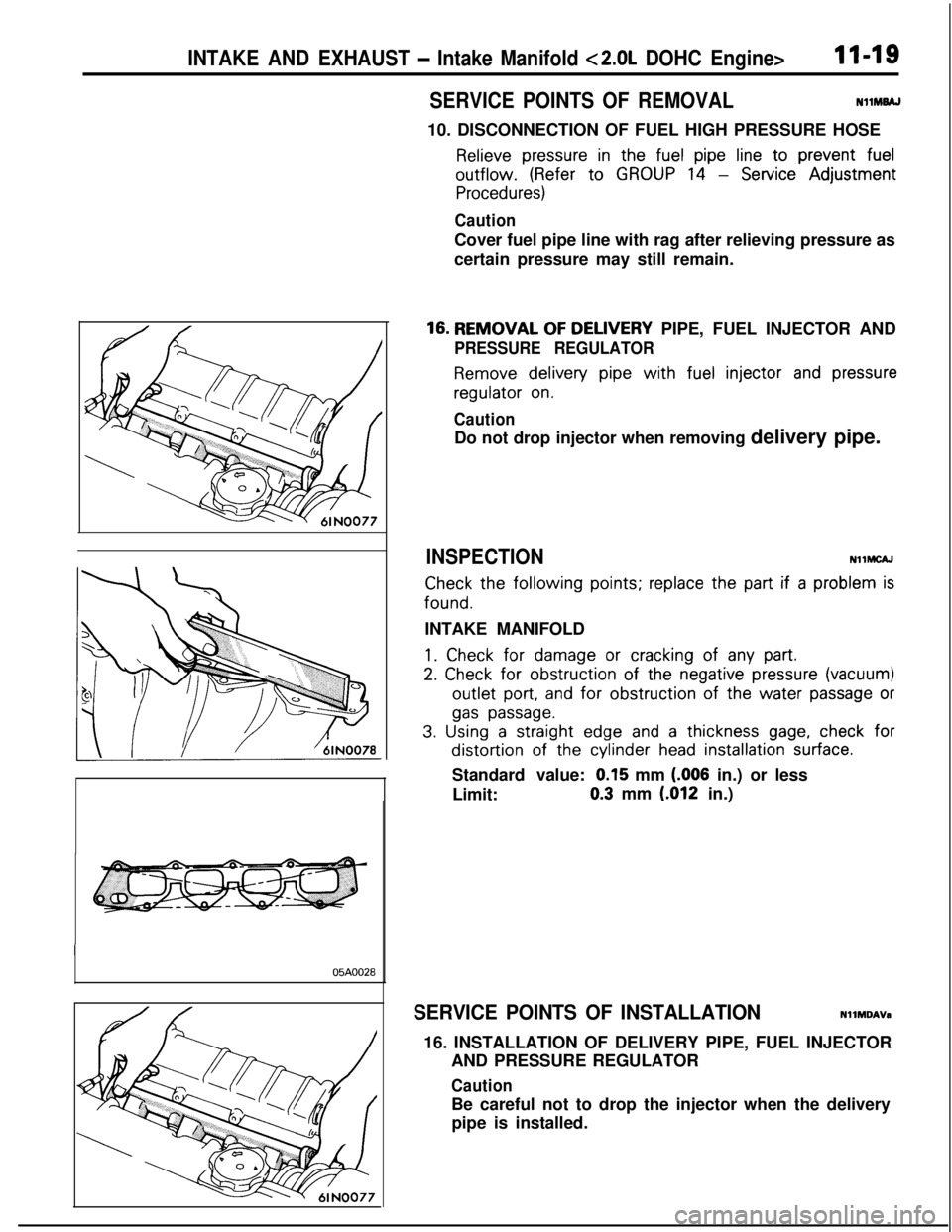
10. DISCONNECTION OF FUEL HIGH PRESSURE HOSE
Relieve pressure in the fuel pipe line to prevent fueloutflow.
(Refer to GROUP 14 - Service Adjustment
Procedures)
CautionCover fuel pipe line with rag after relieving pressure as
certain pressure may still remain.
05AOO28
16. REMOVAL OF DELIVERY PIPE, FUEL INJECTOR AND
PRESSURE REGULATOR
Remove delivery pipe with fuel injector and pressureregulator
on.
CautionDo not drop injector when removing delivery pipe.
INSPECTIONNllMCAJ
Check the following points; replace the part if a problem isfound.
INTAKE MANIFOLD
1. Check for damage or cracking of any part.
2. Check for obstruction of the negative pressure (vacuum)outlet
port, and for obstruction of the water passage or
gas passage.
3. Using a straight edge and a thickness gage, check fordistortion of the cylinder
head installation surface.Standard value:
0.15 mm (.006 in.) or less
Limit:0.3 mm
(012 in.)
SERVICE POINTS OF INSTALLATIONNllMDAVa
16. INSTALLATION OF DELIVERY PIPE, FUEL INJECTOR
AND PRESSURE REGULATOR
CautionBe careful not to drop the injector when the delivery
pipe is installed.
Page 455 of 1216

14-IFUEL SYSTEM
CONTENTS
AUTO-CRUISECONTROLSYSTEM...........................................109AUTO-CRUISECONTROL.......................................................140SERVICEADJUSTMENTPROCEDURES..............................135Accelerator Cable, Throttle Cable and Auto-cruise
ControlCableInspectionandAdjustment........................136Auto-cruise
ControlSystemInspection.............................135lndrvrdualPartsInspection..................................................137SPECIFICATIONS.....................................................................109GeneralSpecifications.......................................................109ServiceSpecifications
.........................................................109Torque Specrfications..........................................................109TROUBLESHOOTING...............................................................110Auto-CruiseControlCircurt................................................128Auto-cruise
ControlComponentsLocation........................126Auto-cruise Control Related Harnesses
.............................125Check Chart
........................................................................114Input Check.........................................................................123Self-diagnosis
Check..........................................................121Troubleshootrng
Quick-referenceChart..............................110ENGINECONTROL.......................................................................105ENGINECONTROL..................................................................107--SERVICEADJUSTMENTPROCEDURES..............................106Accelerator Cable Inspection and Adjustment..................106Accelerator Switch Inspectron and Adjustment................106SPECIFICATIONS.....................................................................105Lubricants.............................................................................105Sealant.................................................................................105ServiceSpecifications
..........................................................105TorqueSpecifications..........................................................105TROUBLESHOOTING...............................................................105FUELSYSTEM..............................................................................2FUELFILTER............................................................................104FUELLINEANDVAPORLINE..............................................102FUEL PUMP, FUEL GAUGE UNIT ANDOVERFILL LIMITER(TWO-WAY VALVE)
Switch........................................................64Air Conditioner Power Relay
..............................................67Components
Location......................................................56
ControlRelay
.................................................................66EGRControlSolenoidValve...............................................67EGRTemperatureSensor..................................................64Engine Coolant Temperature Sensor
.................................62IdlePosrtionSwitch
...........................................................63IdleSpeedControlServo
.............................
....................65InhibitorSwitch....................................................................65hjeCtOrS................................................................................65IntakeAirTemperatureSensor..........................................6’2MalfunctionlndtcatorLight
..........................................58MotorPosition
Sensor................................................63OxygenSensor
.................................................................64Power Steering 011 Pressure Swatch...........................65PowerTransistor
................................................................67PurgeControlSolenoidValve.........................................67
Self-Diagnosis.......................................................................
ThrottlePositronSensor.....................................................
Vehicle Speed Sensor.........................................................MPI
SYSTEMINSPECTION<2.0L DOHCEngine>...........Air Conditioner Power Relay..............................................
Arr Conditioner Swatch........................................................
Components Location
.........................................................
Control
Relay.......................................................................
EGR Control Solenoid Valve...............................................
EGR Temperature Sensor
...................................................
Engine Coolant Temperature Sensor
.................................Fuel Pressure Control Valve...............................................
Idle Position Switch
............................................................
Idle
SpeedControlServo...................................................Injectors
................................................................................
Intake Air Temperature Sensor..........................................
Malfunction Indicator Light.................................................
Oxygen Sensor
....................................................................
Power
Steering
OilPressureSwitch.................................Power Transistor
.................................................................
Purge Control Solenoid Valve.............................................
Self-Diaanosis.......................................................................
58
63
2382
79
688182
79
7682
77
79
79
76
727879
82
8273ThrottletiPosition Sensor
.....................................................77Vehicle Speed Sensor
.........................................................79SERVICE ADJUSTMENT PROCEDURES<1.8L Engine>........................................................................41Curb Idle Speed Inspection
................................................41EGR Valve Control Vacuum Check....................................47Fuel Pressure Test
..............................................................44Fuel Pump Operation Check
..............................................44Idle Speed Control and Throttle Position
Sensor Adjustment
..............................................................
41Purge Port Vacuum Check
.................................................47Release of Residual Pressure from
High Pressure Fuel Hose
...................................................
44Throttle
Body(Throttle Valve Area)Cleaning....................43SERVICE ADJUSTMENT PROCEDURES<2.0LDOHCEngine>............................................................48Basic Idle Speed Adjustment
.............................................
48
Curb Idle Speed Inspection
................................................48EGR Valve Control Vacuum Check....................................55Fuel Pressure Test
..............................................................52Fuel Pump Operation Check
..............................................51Idle Position Switch Adjustment........................................52Purge Port Vacuum Check
.................................................55Release of Residual Pressure from
High Pressure Fuel Hose
...................................................51Throttle Body (Throttle Valve Area) Cleaning....................51ThrottlePositionSensorAdjustment.................................50SPECIALTOOLS......................................................................6SPECIFICATIONS.....................................................................2GeneralSpecifications.........................................................2Sealant and Adhesive
.........................................................5Service Specifications
..........................................................4Torque Specifications
..........................................................5THROlTLEBODY<1.8LEngine>........................................85THROlTLE BODY <2.0L DOHC Engine>............................89TROUBLESHOOTING...............................................................6
Page 456 of 1216

14-2FUEL SYSTEM - Specifications
FUEL SYSTEM
SPECIFICATIONS
GENERAL SPECIFICATIONSNW%-
4.8L Engine>
Items
Fuel
Tank capacity
Return system
Filter
Fuel pump
Type
Driven by
Throttle bodyThrottle
bore
Throttle position sensor
Idle speed control servo
Idle position switchMotor position
sensor
Engine control unitIdentification
model No.
For Federal and Canada
For California
SensorsAir flow
sensor
Barometric pressure sensor
Intake air temperature sensor
Engine coolant temperature sensorOxygen
sensor
Vehicle speed sensorInhibitor switch
No. 1 cylinder top dead center sensor
Crank angle sensor
EGR temperature sensor
Control relay type
Injector type and number
Injector identification mark
Purge control solenoid valve
EGR control solenoid valve
Fuel pressure regulator
Regulated pressure
Specificationsliter
(gal.) 60 (15.9)
Equipped
High pressure type
Electrical, in-tank type
Electric motor
mm (in.) 50 (1.97)
Variable resistor type
Electric motor
Contact type, within idle speed control servo
Variable resistor type
E2T33674
E2T33673
Karman vortex type
Semiconductor diffusion typeThermistor typeThermistor type
Zirconia type
Reed switch type
Contact switch type
Photo interrupter type
Photo interrupter typeThermistor type
Contact switch type
Electromagnetic, 4
N210H
ON/OFF type solenoid valveDuty
cycle type solenoid valve
kPa (psi) 335 (47.6)
Page 457 of 1216

FUEL SYSTEM - Specifications14-3
<2.0L DOHC Engine>
ItemsSpecifications
Fuel
Tank capacityliter (gal.) 60 (15.9)
Return systemEquipped
FilterHigh pressure type
Fuel pump
TypeElectrical, in-tank type
Driven byElectric motor
Throttle bodyThrottle
boremm (in.) 60 (2.36)Throttle position
sensorVariable resistor type
Idle speed control servoStepper motor type
The stepper motor type by- ass air controlsystem with the Fast Idle6!rr Valve (FIAV)
Idle position switchContact switch type
Engine control unitIdentification
model No.
For Federal
E2T36574
E2T36576
E2T36578
E2T36582
For California
E2T36573
E2T36575
E2T36577
E2T36581
SensorsAir flow
sensorKarman vortex type
Barometric pressure sensorSemiconductor diffusion-type
Intake air temperature sensorThermistor type
Engine coolant temperature sensorThermistor type
Oxygen sensorZirconia type
Vehicle-speed sensorReed switch typeDetonation
sensor
Top dead center sensorPhoto interrupter type
Crank angle sensorPhoto interrupter type
EGR temperature sensor
Power steering oil pressure switchContact switch type4ctuators
Control relayContact switch type
Resistor identification model No.E8T05873
Injector type and numberElectromagnetic, 4
Injector identification mark
B450L
B390L
Purge control solenoid valveON/OFF type solenoid valve
EGR control solenoid valve
Fuel pressure control solenoid valve
gate solenoid valve
Page 458 of 1216

FUEL SYSTEM- Specifications
ItemsSpecifications
Fuel pressure regulator
Regulated pressurekPa (psi)
255 (36.3)
SERVICE SPECIFICATIONS
<1.8L Engine>N14CB-
ItemsSpecifications
Basic ignition timing~
Curb idle speedvm
, Idle speed when air conditioner is onrpm
Basic idle speedwm
Throttle position sensor adjusting voltageV
Throttle position sensor resistancekQMotor position
sensor resistancek&
Idle speed control servo motor coil resistance
Intake air temperature sensor resistancekQ
Engine coolant temperature sensor resistance
20°C (68°F)
80°C (176°F)
Fuel pressurekPa (psi)
Vacuum hose disconnection
Vacuum hose connection
Iniectnr coil resistance Q
52
k8
5”BTDC at curb idle
700f 100
850 at neutral position
650 at D range
700 f 50
0.48-0.52 at curb idle
3.5-6.5
4-6
5-35 [at 20°C (68”F)l
2.7 [at 20°C (68”F)I
2.5
0.3
330-350 (47-50) at curb idleApprox.
270 (38) at curb idle
13-16 [at 20°C (68”F)l
<2.0L DOHC Engine>
Items( Specifications
Basic ignition timing
Curb idle speedrpm
Idle speed when air conditioner is onrpm
al-r>
Basic idle speedrpm
Throttle position sensor adjustment voltageVThrottle position
sensor resistancekQ
Idle speed control servo (stepper motor) coil resistance
Intake air temperature sensor resistancekQ
Engine coolant temperature sensor resistancek0
20°C (68°F)
80°C (176°F)
Fuel pressurekPa (psi)
Vacuum hose disconnection
Vacuum hose connection
Q
5”+ 2”BTDC at curb idle
750+ 100
850 at neutral position
650 at D range
750 f 50
0.48-0.52 at curb idle
3.5-6.5
28-33 [at 20°C (68”F)l
2.7 [at 20°C (68”F)I
2.5
0.3
330-350 (47-50) at curb idle
250-270 (36-38) at curb idle
290-320 (41-46) at curb idleApprox.
270 (38) at curb idle
Approx. 190 (27) at curb idle
Approx. 230 (33) at curb idle
Page 459 of 1216

FUEL SYSTEM - SDecifications14-5
-.
Items
Injector coil resistance52
Specifications
13-I 6 [at 20°C (68”F)j
2-3 [at 20°C (68”F)I
TORQUE SPECIFICATIONSN14CC-A
,,-
ItemsINm1 ft.lbs.
Center cover
Oxygen sensor
Engine coolant temperature sensor
Throttle position sensor attaching screws
Idle speed control servo attaching screws <2.0L DOHC Engine>
Delivery pipe mounting bolts
High-pressure fuel hose to delivery pipe
Fuel pressure regulator to delivery pipe
<1.8L Engine>
<2.0L DOHC Engine>
Accelerator cable clamp
Throttle body mounting bolts and nuts
Throttle body stay mounting nut
4ccelerator cable adjusting bolts
Lateral rod attaching bolt
Self-locking nut
Fuel tank drain plug
Electrical fuel pump
Screws
Bolt (at lower side)Gel
gauge unit mounting screws
-ligh pressure hose to electrical fuel pump
iigh pressure hose to fuel main pipe
3attery tray to battery
3attery tray mounting boltGel
main pipe to fuel filter
Zye boltGel filter
mounting bolts
%el pipes clip attaching bolt
Japor pipe assembly mounting bolt
Ianister holder mounting bolt
2.5-3.5
40-50
20-40
1.5-2.5
2.5-4.5
IO-13
4-6
7-l 15-8
8-106-7
IO-137-9
15-2211-16
15-2211-16
4-63-4
80-l 0057-72
21-3115-22
15-2011-14
2-3
9-14
2-3
30-40
30-40
2-3
9-14
30-40
25-35
9-14
9-14
9-14
9-14
2-3
30-36
15-29
1.1-1.8
1.8-3.3
7-9
3-4
1.4-2.2
6.5-10
1.4-2.2
22-29
22-29
1.5-2
7-14
22-29
18-25
7-10
7-10
7-10
7-10
SEALANT AND ADHESIVENMCE-A
Items
Engine coolant temperature sensor threaded portion
Fuel tank hole cover
Specified sealant
MOPAR Part No.4318034 or equivalent
MOPAR Rope Caulk Sealer 3/l 6 x 80” roll Part No.4026044 or equivalent