Page 556 of 1216

14-102FUEL SYSTEM - Fuel Line and Vapor Line
FUEL LINE AND VAPOR LINEREMOVAL AND INSTALLATION
NuKn-
rPre-removal Operationl Removal of the Batten/ Trav(Refer to GROUP 8-Starter Motor)ORelease of Residual Pressure from High
Pressure Hose.(Refer to
P.14-44.)
1Post-installation Operation*Measurement of Fuel Pressure (Refer toP.1444, 52.)l lnstallatron of the Battery Tray(Refer to GROUP 8-Starter Motor)4-6
Nm25-35 Nm3-4 ft.lbs.16-25 ftlbs.9-14 Nm7-10
ftlbs.
I
7-9-14
Nm30-40 Nm7-10 ft.lbs.22-29 ft.lbs.
9-14 Nm
7-10 ftlbs.
9-14Nm7-10 ft.lbs.9-h Nm
7-10ft.lbs.9-i4 Nm7-10ft.lbs.9-14
Nm7- 10ft.lbs.25-35
Nm16-25 ft.lbs.
7-10 ft.lbs. 7-10 ft.lbs.
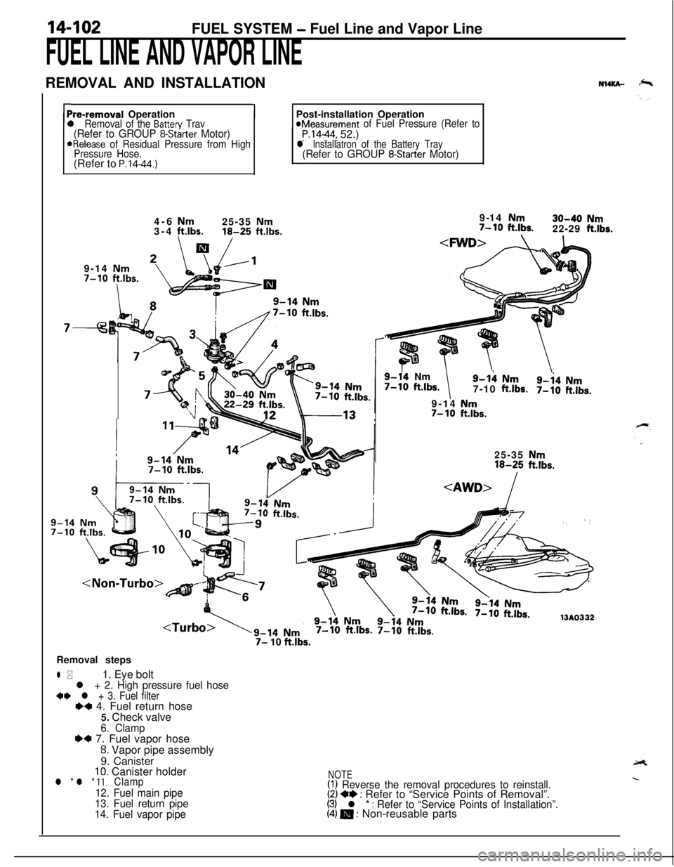
7- 10 ft.lbs.Removal steps
l *1. Eye boltl + 2. High pressure fuel hose+e l + 3. Fuel filterI)+ 4. Fuel return hose
5. Check valve
6. Clamp~~ 7. Fuel vapor hose
8. Vapor pipe assembly
9. Canister
10. Canister holderl * l * 11.Clamp
12. Fuel main pipe
13. Fuel return pipe
14. Fuel vapor pipe
NOTE(I) Reverse the removal procedures to reinstall.(2) +e : Refer to “Service Points of Removal”.(3) l * : Refer to “Service Points of Installation”.(4) m : Non-reusable parts
Page 557 of 1216

-.FUEL SYSTEM
- Fuel Line pnd Vapoi- @f&
L
Mounting
bolts
pipe
03FOOO
!-03FOO7 [SERVICE. POINTS
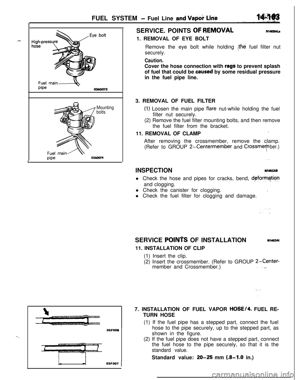
OF REMOVALN14KSAl.a1. REMOVAL OF EYE BOLT
Remove the eye bolt while holding the’ fuel filter nut
securely.
Caution.Cover the hose connection with
ragS: to prevent splash
of fuel that could be
caked by some residual pressure
in the fuel pipe line.
3. REMOVAL OF FUEL FILTER
(1) Loosen the main pipe blare nut-while holding the fuel
filter nut securely.
(2) Remove the fuel filter mounting bolts, and then remove
the fuel filter from the bracket.
11. REMOVAL OF CLAMP
!After removing the crossmember, remove the clamp.
(Refer to GROUP
2-Centermember and CrossmeTber.),.
INSPECTIONNi&CABl Check the hose and pipes for cracks, bend,
d,eforrnatiorrand clogging.
l Check the canister for clogging.
1l Check the fuel filter for clogging and damage.
SERVICE
POINTS OF INSTALLATION~aNl4KDAl11. INSTALLATION OF CLIP
(1) Insert the clip.
(2) Insert the crossmember. (Refer to GROUP
2-Center-member and Crossmember.),. ,,$l
”7. INSTALLATION OF FUEL VAPOR
HOSE/4. FUEL RE-
TURN HOSE
(1) If the fuel pipe has a stepped part, connect the fuel
hose to the pipe securely, up to the stepped part, as
shown in the figure.
(2) If the fuel pipe does not have a stepped part, connect
the fuel hose to the pipe securely, so that it is the
standard value.Standard value:
20-25 mm (.&I.0 in.)
Page 558 of 1216

FUEL SYSTEM - Fuel Line and VaDor Line/Fuel Filter
High-pressur
hose
f+-----Eye bolt
Gasket
Fuel filter
Flare nut
Fuel main
pipe
\-Apply engine
&ring Oi’
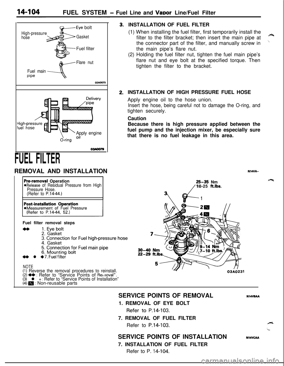
FUEL FILTERREMOVAL AND INSTALLATION3.2.INSTALLATION OF FUEL FILTER
(1) When installing the fuel filter, first temporarily install the
filter to the filter bracket; then insert the main pipe at
‘*the connector part of the filter, and manually screw in
..the main pipe’s flare nut.
(2) Holding the fuel filter nut, tighten the fuel main pipe’s
flare nut and eye bolt at the specified torque. Then
tighten the filter to the bracket.
Pre-removal Operation@Release of Residual Pressure from High
Pressure Hose.
(Refer to P.14-44.)IIFuel filter removal steps
**1. Eye bolt2. Gasket3. Connection for Fuel high-pressure hose
4. Gasket
5. Connection for Fuel main pipe6. Mounting bolt+e l 4 7. Fuel filter
NOTE(1) Reverse the removal procedures to reinstall.(2) +e : Refer to “Service Points of Removal”.(3) l + : Refer to “Service Points of Installation”(4) m : Non-reusable partsINSTALLATION OF HIGH PRESSURE FUEL HOSE
Apply engine oil to the hose union.
Insert the hose, being careful not to damage the O-ring, andtighten securely.
Caution
Because there is high pressure applied between the
fuel pump and the injection mixer, be especially sure
that there is no fuel leakage in this area.
N14VA-25-35 Nm
18-25
ft.lbs.
vd-
7’
1
Y03A0231SERVICE POINTS OF REMOVAL
NlIVBAA1. REMOVAL OF EYE BOLT
Refer to P.14-103.
7. REMOVAL OF FUEL FILTER
Refer to
P.14-103.SERVICE POINTS OF INSTALLATION
7. INSTALLATION OF FUEL FILTER
Refer to P. 14-104.
N14VCAA
Page 1200 of 1216
25-4EMISSION CONTROL SYSTEMS - Vacuum HosesVACUUM HOSES
VACUUM HOSES ROUTING
1.8L Engine>
hW7JA-
r”
w..’L:
Light blueR:
RedB:
BlackCanister,Purge control
/solenoid valve
Fuel pressure
regulator
Vehicle front
3EM0123
<-LCalifornia- 1.8L Engine>
CanisterThrottle body
aVehicle front G: Green
Y : Yellow
L : Light blueR: Red
B : Black/EGR valve
-Fuel pressure
regulator
3EM0124
Page 1201 of 1216
EMISSION CONTROL SYSTEMS - Vacuum Hoses2515
Canada-2.0L DOHC Engine Non-Turbo>
Purge control
solenoid valve
Canister
Therm0valve
G: Green
Y : Yellow
L : Light blueR: Red
B : Black
nVehicle frontFuel pressure
regulator6EM0191
G: Green
Y : YellowPurge control
solenoid valve
Cani
EGR controlsolenoid valve
EGR valve
L : Light blue
R: Red
B : BlackVehicle frontFuel pressure
regulator
6EM0192
Page 1202 of 1216
25-6EMISSION CONTROL SYSTEMS - Vacuum Hoses
Canada-2.0L DOHC Engine Turbo>
G: Green
Y : Yellow
L : Light blueR: Red
B : Black
W: White
Purge control valvg
Purge controlFuel pressure control,solenoid valve/solenoid valve
Therm0 valve’
el pressure regulator
Turbocharger
vvasre gate actuator Waste gate control
solenoid valveVehicle front
6EM0222
G: Green
Y : Yellow
L : Lrght blueR: Red
B : Black
W: White
1sPurge control valve
&+
Air cleanerFuel pressure control
solenoid valve.
Purge control
solenoid valve\Fuel pressure regulator
Waste gate control
solenord valve
Waste gate actuatorv.,~~‘~y:‘;7Vehicle front
6EM0223