1991 MITSUBISHI ECLIPSE coolant level
[x] Cancel search: coolant levelPage 37 of 1216

LUBRICATION AND MAINTENANCE - Scheduled MaintenanCe Table. &3
SCHEDULED MAINTENANCE TABLE1
- SCHEDULED MAINTENANCE SERVICES FOR EMISSION CONTROL AND PRO;;
VEHICLE PERFORMANCEInspection and Services should be performed any time a malfunction is observed or suspected. Retain
receipts for all vehicle emission services to protect your emission warranty.
Kilometers in Thousands 24 48 72 80 96
No.Emission Control System Maintenance
Service IntervalsMileage in Thousands 15 30 45 50 60
1Check Fuel System (Tank, Line and Connections and Fuel Filler Cap) for Leaks
Every 5 YearsorX
2Check Fuel Every 2 Years for Leaks or DamageorXX
3Replace Air Cleaner Element
atXX
4Replace Spark Plugs
atXXGENERAL MAINTENANCE SERVICE FOR PROPER VEHICLE PERFORMANCE
Yo. General Maintenance
Service IntervalsKilometers in Thousands 24 48 72 80 9cMileage in Thousands 15 30 45 50
6C
5Timing Belt (Including theBalancer Belt)ReplaceatX
6Drive Belt (for Water Pump
and Alternator)Inspect for tensionatXX.’
Non-TurboChange Every YearEvery 12 000 kmOr (7,500 miles).
7Engine Oil
TurboChange Every 6 MonthsEvery 8,000 km
(5,000 miles)
Non-TurboChange Every Yearor X X XX
8Engine Oil
Filter
TurboChange Every YearEvery 16,000 km
(10,000 miles)
9Manual Transaxle OilInspect Oil LevelatX.X
Inspect Fluid Level Every Yearor X X XX
10Automatic Transaxle Fluid
Change FluidatXX11 Engine Coolant
Replace Every 2 YearsorXX
12Disc Brake PadsInspect for Wear Every Yearor X X XX13 Brake Hoses
Check for Deterioration or Leaks Every YearX X XX
l 4Beiloint and Steering Linkageinspect for Grease Leaks and Damage Every
2 YearsorXX
15Drive Shaft BootsInspect for Grease Leaks and Damage Every Yearor XXXX
Rear Axle
With LSDChange OilXX1 6
Exhaust System (Connection17Portion of Muffler, Pipings andCheck and Service as Required Every 2 Yearsorx -xConverter Heat Shields)
NOTELSD: Limited-slip differential
Page 40 of 1216

O-6LUBRICATION AND MAINTENANCE - Capacities TableRecommended Lubricants and Lubricant
72A0044Oil Identification Symbol
A standard symbol appears on the top of oil containers and hasthree district areas for identifying various aspects of the oil.
The top portion will indicate the quality of the oil. The center
portion will show the SAE viscosity grade, such as SAE
IOW-30. “Energy Conserving” shown in the lower portion,
indicates that the oil has fuel-saving capabilities.
REAR AXLE
LubricantAPI classification
GL-5 or higher
Anticipated temperature rangeViscosity rangeAbove -23°C
(-10°F)SAE 90SAE 85W-90SAE 8OW-90
-23°C to -34°C (-10°F to -30°F)SAE 8OW, SAE 8OW-90Below -34°C
(-30°F)SAE 75WSELECTION OF COOLANT
COOLANTRelation between Antifreeze Concentration and Specific Gravity
concentration
ExampleThe safe operating temperature is
- 15°C (5°F) when the measured specific gravity is 1.058 at the coolant
temperature of
20°C (68°F).
Cautions1. If the concentration of the coolant is below 30%, the anti-corrosion property will be adversely
affected. In addition, if the concentration is above 60%, both the anti-freeze and engine cooling
properties will decrease, affecting the engine adversely. For these reasons, be sure to maintain theconcentration level within the specified range.
2. Do not use a mixture of different brands of anti-freeze.
Page 46 of 1216

LUBRICATION AND MAINTENANCE - Maintenance Service
L-4GoodOOA0051C9FW1014K512(9) Supply 4 liters (8.5 pints) of specified ATF into case
through dipstick hole. [Total quantity of ATF required is
6.1 liters (12.9 pints).
Actually however, approx. 4.5 liters (9.5 pints) of fluid
can be replaced because rest of fluid remains in torque
converter.]Specified fluid: MOPAR ATF PLUS (Automatic
Transmission Fluid Type 7176) or
Dia ATF SP or Equivalent
(10)Start engine and allow to idle for at least two minutes.
Then, with parking brake on, move selector lever
momentarily to each position, ending in “N” Neutral
position.
(1 l)Add sufficient ATF to bring fluid level to lower mark.
Recheck fluid level after transaxle is at normal operating
temperature.
Fluid level should be between upper and lower marks of“HOT” range. Insert dipstick fully to prevent dirt from
entering transaxle.
11 .ENGINE COOLANT (Change)NOOSBEAcCheck the cooling system parts, such as radiator, heater,
and oil cooler hoses, thermostat and connections for
leakage and damage.
CHANGE COOLANT
1. Remove the radiator cap.
2. Loosen the drain plug to drain the coolant.
3. Drain the coolant from the reserve tank.
4. After draining the coolant, tighten the drain plug
securely.
5.Supply the coolant into the radiator until it is filled up to
its filler neck.
6. Supply the coolant into the reserve tank.
7. After warming the engine until the thermostat opens,
remove the radiator cap and check the coolant level.
8.Supply the coolant into the radiator until it is filled up to
its filler neck, and install the
.radiator, cap securely.
9.Fill the reserve tank with coolant up to the “FULL” line.12DISC BRAKE PADS (Inspect for wear)
NOOSBFA~Check for fluid contamination and wear. Replace complete
set of pads if defective.
Caution
The pads for the right and left wheels should be
replaced at the same time. Never “split” or intermix
brake pad sets.
All four pads must be replace as a complete set.
Thickness of lining (A)
Limit
:2.0 mm (.08 in.)
Page 256 of 1216

7-8COOLING - Service Adjustment Procedures
04DooE
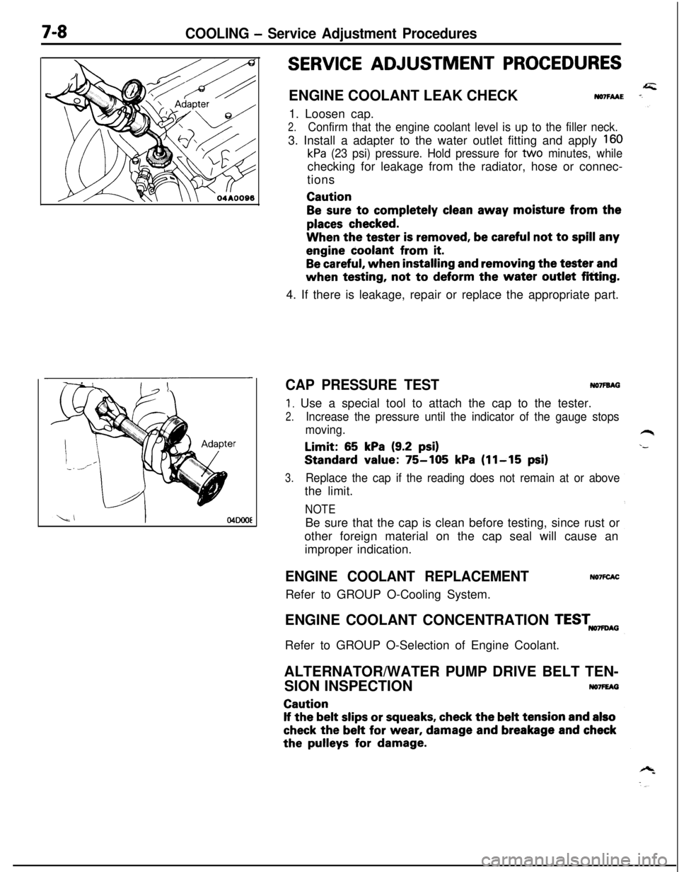
SERVICE ADJUSTMENT PROCEDURESENGINE COOLANT LEAK CHECK
NO7FAAE1. Loosen cap.
2.Confirm that the engine coolant level is up to the filler neck.3. Install a adapter to the water outlet fitting and apply
160
kPa (23 psi) pressure. Hold pressure for tvvo minutes, whilechecking for leakage from the radiator, hose or connec-
tionsCaution
Be sure to completely clean away moisture from the
places checked.When the tester
is removed, be careful not to spill anyengine coolant from
it.
Be careful, when installing and removing the tester andwhen testing, not
to deform the water outlet fitting.
4. If there is leakage, repair or replace the appropriate part.
CAP PRESSURE TESTNO’IFBAG
1. Use a special tool to attach the cap to the tester.
2.Increase the pressure until the indicator of the gauge stops
moving.Limit:
65 kPa (9.2 psi)Standard value:
75-105 kPa (11-15 psi)
3.Replace the cap if the reading does not remain at or abovethe limit.
NOTEBe sure that the cap is clean before testing, since rust or
other foreign material on the cap seal will cause an
improper indication.
ENGINE COOLANT REPLACEMENTRefer to GROUP O-Cooling System.NO’IFCACENGINE COOLANT CONCENTRATION
TESTmAGRefer to GROUP O-Selection of Engine Coolant.
ALTERNATOR/WATER PUMP DRIVE BELT TEN-
SION INSPECTION
NO7FEAGCaution
If the belt slips or squeaks, check the belt tension and also
check the belt for wear, damage and breakage and checkthe
pulleys for damage.
Page 260 of 1216

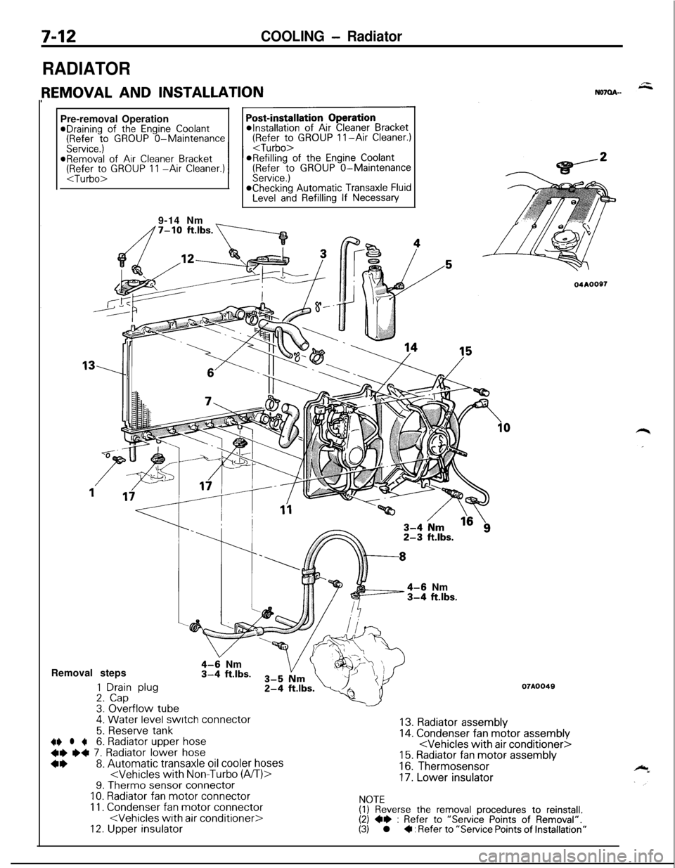
7-12COOLING - Radiator
RADIATORPre-removal Operation
@Draining of the Engine Coolant(Refer to GROUP O-Maintenance(Refer to GROUP II-Air Cleaner.)
Service.)
I I
9-14 Nm
_
4-6 Nm3-4 ft.lbs.Removal steps
1 Drain plug2. Cap3. Overflow tube.
4-9 Nm3-4 ft.lbs.
4. Water level switch connector
5. Reserve tank~~ l +6. Radiator upper hose
+e e+ 7. Radiator lower hose
*I)8. Automatic transaxle oil cooler hoses
11. Condenser fan motor connector
04AOOS7
07A0049
13. Radiator assembly14. Condenser fan motor assembly
16. Thermosensor
17. Lower insulator
NOTE(1) Reverse the removal procedures to reinstall.(2) +e : Refer to “Service Points of Removal”.(3) l + : Refer to “Service Points of Installation”
Page 279 of 1216

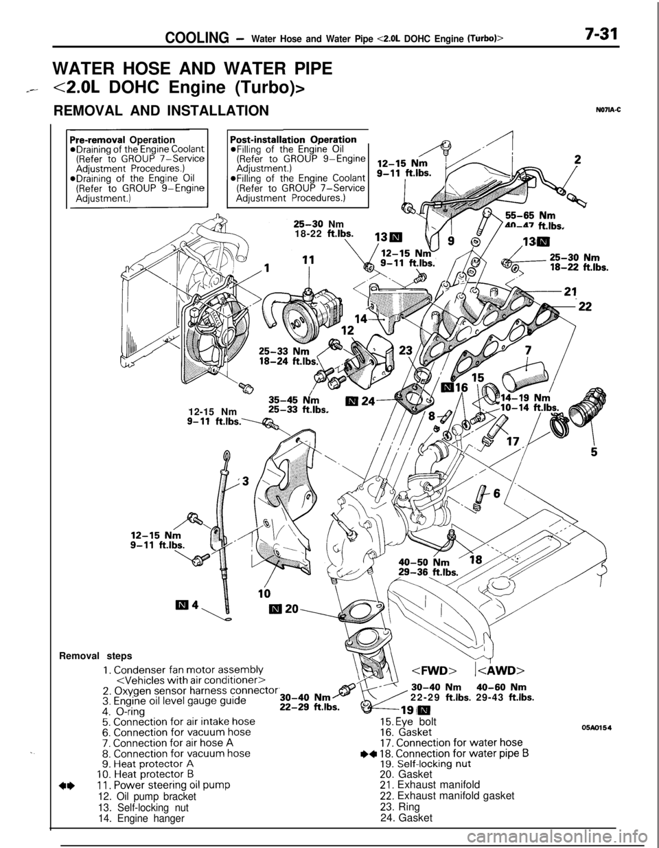
COOLING -Water Hose and Water Pipe <2.0L DOHC Engine (Turbo)>7-31WATER HOSE AND WATER PIPE
7--<2.0L DOHC Engine (Turbo)>
REMOVAL AND INSTALLATION
N071A-C
. .
ation OperationPost-installi@Filling of the Engine Oil(Refer to GROUP g-EngineaFilling of the
Engine Coolant(Refer to GROUP 7-ServiceAdjustment Procedures.)
Pre-removal OperationeDraining of the Engine Coolant(Refer to GROUP 7-ServiceAdjustment Procedures.)*Draining of the Engine Oil(Refer to GROUP g-Engine
25-30 Nm
18-22 ftlbs.4n-47 ft.lbs.
w35-45 N/m12-15 Nm25-33 ft.lbs.
9- 11ft.lbs.----Q&Removal steps
1. Condenser fan motor assembly
4*11. Power steering oil pump
12. Oil pump bracket
13. Self-locking nut
14. Engine hanger22-29
ft.lbs. 29-43 ft.lbs.
15. Eye bolt16. Gasket17. Connection for water hose
I)+ 18. Connection for water pipe B19. Self-locking nut20. Gasket21. Exhaust manifold22. Exhaust manifold gasket
23. Ring
24. Gasket
05m154
Page 442 of 1216

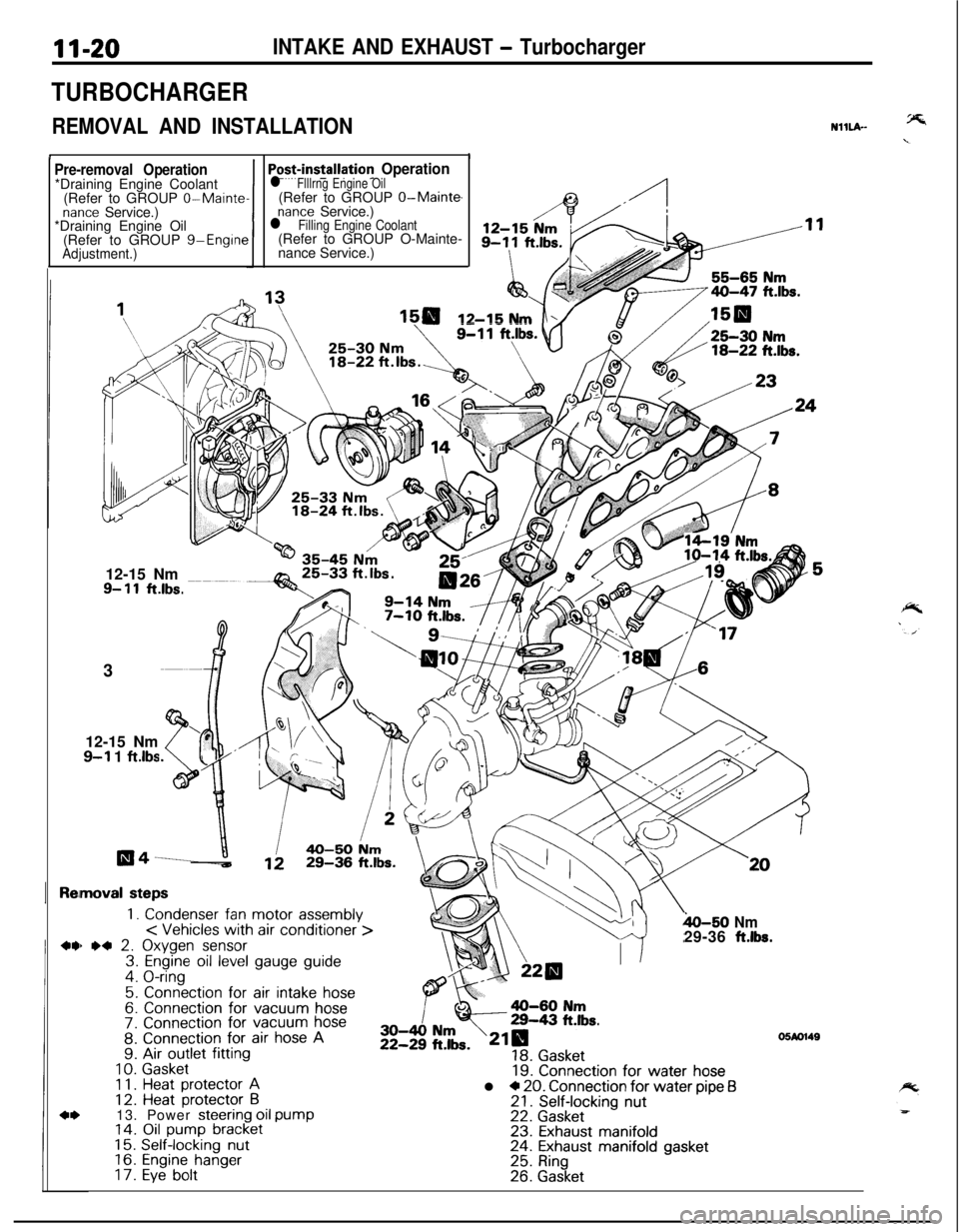
II-20INTAKE AND EXHAUST - Turbocharger
TURBOCHARGER
REMOVAL AND INSTALLATION
II
NHLA-
Pre-removal Operation*Draining Engine Coolant
(Refer to GROUP
0-Maintenance Service.)
*Draining Engine Oil
(Refer to GROUP g-Engine
Adjustment.)1
Po+installation Operationl Flllrng Engine Oil(Refer to GROUP O-Main@
nance Service.)l Filling Engine Coolant(Refer to GROUP O-Mainte-
nance Service.)
12-15 Nm12-15 Nm
9- 11ft.lbs.3
12-15 Nm
9-l 1 ftlbs
moval steps
1. Condenser fan motor assembly< Vehicles with air conditioner >) *4 2. Oxygen sensor3. Engine oil level gauge guide4. O-ring
5. Connection for air intake hose6. Connection for vacuum hose7. Connection for vacuum hose8. Connection for air hose A9. Air outlet fitting
10.Gasket1 1.Heat protector A12. Heat protector B13. Power steering oil pump14. Oil pump bracket15.Self-locking nut16.Engine hanger17.Eye bolt
h-50 Nm29-36 ft.lbs.
19. Connection for water hosel * 20. Connection for water pipe f321. Self-locking nut22. Gasket23. Exhaust manifold24. Exhaust manifold gasket25. Ring26. Gasket
05M1149
Page 450 of 1216

11-28INTAKE AND EXHAUST - Exhaust Manifold ~2.0~ DOHC Enoine (Turbo)>
EXHAUST MANIFOLD <2.0L DOHC Engine (Turbo)>
REMOVAL AND INSTALLATION
Pre-removal Operation*Draining Engine Coolant(Refer to GROUP O-Mainte-nance Service.)*Draining Engine Oil(Refer to GROUP O-Mainte-nance Service.)
Rennova1 steps
1.Condenser fan motor assembly
\30-40 Nm22-29 ft.lty3. & (
EJ\\=a-50 N
4 .ri29-38 ftk.
,
Post-installation Operation@Filling Engine Oil(Refer to GROUP O-Mainte-nance Service.)@Filling Engine Coolant(Refer to GROUP O-Mainte-nance Service.)NllNA-C
130 25-30 Nmd/18-22 ft.lbs.
;:4.
s5:7.
::10.Ii.12.13.14.15.
Connection for air intake hose
Connection for vacuum hoseConnection for vacuum hoseConnection for air hose AHeat protector AHeat protector 6Power steering oil pumpOil pump bracketSelf-locking nut
Engine hangerEve bolt
16. Gasket17. Connection for water hose
19IBWI 18. Connection for water pipe B19. Self-locking nut20.
Gasket
05Ao15421.
Exhaust manifold22. Exhaust manifold gasket23.
Ring24. Gasket
NOTE(1) Reverse the removal procedures to reinstall.(2) +, : Refer to “Service Points of Removal”.(3) l * : Refer to “Service Points of Installation”(4) m : Non-reusable parts